- Table of Contents
-
- H3C MSR1000[2600][3600] Routers Configuration Examples All-in-One-R9141-6W100
- 00-Preface
- 01-Local 802.1X Authentication Configuration Examples
- 02-RADIUS-Based 802.1X Authentication Configuration Examples
- 03-AAA Configuration Examples
- 04-ACL Configuration Examples
- 05-MPLS over ADVPN Configuration Examples
- 06-ARP Attack Protection Configuration Examples
- 07-BFD Configuration Examples
- 08-Basic BGP Configuration Examples
- 09-BGP Route Attribute-Based Route Selection Configuration Examples
- 10-EAA Monitor Policy Configuration Examples
- 11-GRE with OSPF Configuration Examples
- 12-HoVPN Configuration Examples
- 13-IGMP Snooping Configuration Examples
- 14-IGMP Configuration Examples
- 15-IPsec Configuration Examples
- 16-IPsec Digital Certificate Authentication Configuration Examples
- 17-IPv6 IS-IS Configuration Examples
- 18-IPv6 over IPv4 GRE Tunnel Configuration Examples
- 19-IPv6 over IPv4 Manual Tunnel with OSPFv3 Configuration Examples
- 20-IS-IS Configuration Examples
- 21-Combined ISATAP Tunnel and 6to4 Tunnel Configuration Examples
- 22-L2TP over IPsec Configuration Examples
- 23-Multi-Instance L2TP Configuration Examples
- 24-L2TP Multidomain Access Configuration Examples
- 25-MPLS L3VPN Configuration Examples
- 26-MPLS OAM Configuration Examples
- 27-MPLS TE Configuration Examples
- 28-Basic MPLS Configuration Examples
- 29-NAT DNS Mapping Configuration Examples
- 30-NetStream Configuration Examples
- 31-NQA Configuration Examples
- 32-NTP Configuration Examples
- 33-OSPFv3 Configuration Examples
- 34-OSPF Configuration Examples
- 35-OSPF Multi-Process Configuration Examples
- 36-OSPF Multi-Instance Configuration Examples
- 37-Portal Configuration Examples
- 38-PPP Configuration Examples
- 39-RBAC Configuration Examples
- 40-RMON Configuration Examples
- 41-IPv4 NetStream Sampling Configuration Examples
- 42-SNMP Configuration Examples
- 43-SRv6 Configuration Examples
- 44-SSH Configuration Examples
- 45-Tcl Commands Configuration Examples
- 46-VLAN Configuration Examples
- 47-VRRP Configuration Examples
- 48-VXLAN over IPsec Configuration Examples
- 49-WLAN AC Configuration Examples
- 50-Small and Medium-Sized Store Configuration Examples
- 51-Cloudnet VPN Configuration Examples
- 52-Ethernet Link Aggregation Configuration Examples
- 53-Ethernet OAM Configuration Examples
- 54-Outbound Bidirectional NAT Configuration Examples
- 55-NAT Hairpin in C-S Mode Configuration Examples
- 56-Load Sharing NAT Server Configuration Examples
- 57-BIDIR-PIM Configuration Examples
- 58-Control Plane-Based QoS Policy Configuration Examples
- 59-Scheduling a Task Configuration Examples
- 60-Client-Initiated L2TP Tunnel Configuration Examples
- 61-LAC-Auto-Initiated L2TP Tunnel Configuration Examples
- 62-Authorized ARP Configuration Examples
- 63-GTS Configuration Examples
- 64-Traffic Policing Configuration Examples
- 65-Traffic Accounting Configuration Examples
- 66-Mobile Communication Modem Management Configuration Examples
- 67-Port Isolation Configuration Examples
- 68-PBR Configuration Examples
- 69-TFTP Client Software Upgrade Configuration Examples
- 70-FTP Client Software Upgrade Configuration Examples
- 71-FTP Server Software Upgrade Configuration Examples
- 72-Routing Policy Configuration Examples
- 73-Software Upgrade from the BootWare Menu Configuration Examples
- 74-Mirroring Configuration Examples
- Related Documents
-
| Title | Size | Download |
|---|---|---|
| 30-NetStream Configuration Examples | 419.33 KB |
|
|
|
H3C Routers |
|
NetStream Configuration Examples |
|
|
|
|
Copyright © 2024 H3C Technologies Co., Ltd. All rights reserved.
No part of this manual may be reproduced or transmitted in any form or by any means without prior written consent of New H3C Technologies Co., Ltd.
Except for the trademarks of New H3C Technologies Co., Ltd., any trademarks that may be mentioned in this document are the property of their respective owners.
The information in this document is subject to change without notice.
Introduction
The following information provides examples for configuring IPv4 NetStream and IPv6 NetStream.
Prerequisites
This document is not restricted to specific software or hardware versions. Procedures and information in the examples might be slightly different depending on the software or hardware version of the device.
The configuration examples were created and verified in a lab environment, and all the devices were started with the factory default configuration. When you are working on a live network, make sure you understand the potential impact of every command on your network.
This document assumes that you have basic knowledge of NetStream.
Example: Configuring IPv4 NetStream
Network configuration
As shown in Figure 1, configure IPv4 NetStream on the gateway to monitor traffic and user behavior of internal users in the teaching areas.

Software versions used
This configuration example was created and verified on R9141P16 of the MSR2630E-X1 device.
Restrictions and guidelines
· You must specify the destination UDP port for NetStream data export as the UDP port number of the NetStream server.
· In this configuration example, the NetStream server runs on IMC PLAT 7.0 (E0202).
Procedures
Configuring the gateway
# Enable NetStream for incoming and outgoing traffic on GigabitEthernet 0/0/1.
<Gateway> system-view
[Gateway] interface gigabitethernet 0/0/1
[Gateway-GigabitEthernet0/0/1] ip netstream inbound
[Gateway-GigabitEthernet0/0/1] ip netstream outbound
[Gateway-GigabitEthernet0/0/1] quit
# Specify GigabitEthernet 0/0/2 as the source interface for NetStream data packets.
[Gateway] interface gigabitethernet 0/0/2
[Gateway-GigabitEthernet0/0/2] ip address 10.1.1.1 255.255.255.0
[Gateway-GigabitEthernet0/0/2] quit
[Gateway] ip netstream export source interface gigabitethernet 0/0/2
# Specify 10.1.1.2 as the IP address of the destination host and UDP port 5000 as the export destination port number.
[Gateway] ip netstream export host 10.1.1.2 5000
Configuring IMC
Adding a device
1. Log in to IMC.
2. Click the Service tab.
3. From the left navigation pane, select Traffic Analysis and Audit > Settings.
4. In the Guide to Quick Traffic Analysis And Audit Configuration area, click Device Management.
5. Click Add.
Deploying the server configuration
1. Click the Service tab.
2. From the left navigation pane, select Traffic Analysis and Audit > Settings.
3. On the Settings page that opens, click Server Management.
4. Click the Modify icon for the NTA/UBA server.
5. On the Server Configuration page shown in Figure 3, configure the server parameters and then click Deploy.
Figure 3 Deploying the server configuration
Adding a traffic analysis task
You can add multiple types of traffic analysis tasks. This example uses the interface traffic analysis task type.
To add an interface traffic analysis task:
1. Click the Service tab.
2. From the left navigation pane, select Traffic Analysis and Audit > Settings.
3. On the Settings page that opens, click Traffic Analysis Task Management.
4. Click Add. The Select Task Type page opens.
5. Select Interface and click Next. The Add Traffic Analysis Task page opens.
6. Configure basic information and interface information, and then click OK.
Figure 4 Adding a traffic analysis task
Verifying the configuration
1. Display NetStream data export information.
[Gateway] display ip netstream export
IP export information:
Flow source interface : GigabitEthernet0/0/2
Flow destination VPN instance : Not specified
Flow destination IP address (UDP) : 10.1.1.2 (5000)
Version 5 exported flow number : 8
Version 5 exported UDP datagram number (failed) : 8 (0)
Version 9 exported flow number : 0
Version 9 exported UDP datagram number (failed) : 0 (0)
2. Display the report of the interface traffic analysis task:
a. Click the Service tab.
b. From the left navigation pane, select Traffic Analysis and Audit > Interface Traffic Analysis Task. Use either of the following methods to access the report page of interface traffic analysis task Interface:
- In the Summary List area, click the name of the interface traffic analysis task.
- On the left navigation pane, move your mouse pointer to the shortcut menu icon next to Interface Traffic Analysis Task, and then select Interface from the menu.
Figure 5 Interface traffic analysis
Configuration files
#
interface GigabitEthernet0/0/2
ip address 10.1.1.1 255.255.255.0
#
interface GigabitEthernet0/0/1
ip netstream inbound
ip netstream outbound
#
ip netstream export host 10.1.1.2 5000
ip netstream export source interface GigabitEthernet0/0/2
Example: Configuring IPv6 NetStream
Network configuration
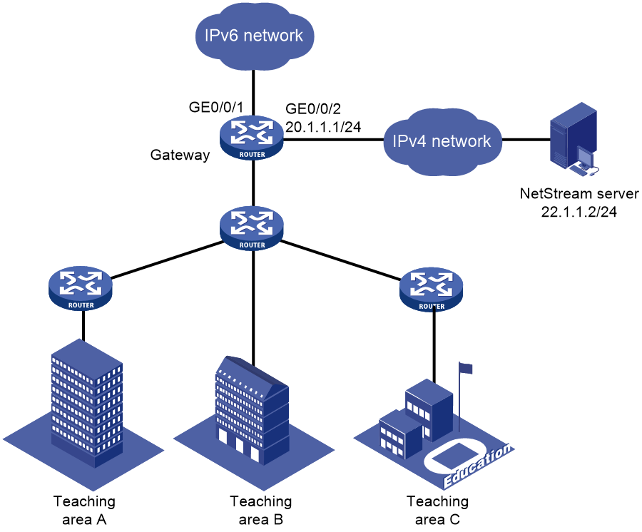
As shown in Figure 6, configure IPv6 NetStream on the gateway to monitor the network access traffic and behavior of internal users.
Software versions used
This configuration example was created and verified on R9141P16 of the MSR2630E-X1 device.
Restrictions and guidelines
· You must specify the destination UDP port for NetStream data export as the UDP port number of the NetStream server.
· In this configuration example, the NetStream server runs on IMC PLAT 7.0 (E0202).
Procedures
Configuring the gateway
# Assign IP address 22.1.1.2/24 to the NetStream server, and make sure the NetStream server and the gateway can reach each other. (Details not shown.)
# Enable IPv6 NetStream for incoming and outgoing traffic on GigabitEthernet 0/0/1.
<Gateway> system-view
[Gateway] interface GigabitEthernet 0/0/1
[Gateway-GigabitEthernet0/0/1] ipv6 netstream inbound
[Gateway-GigabitEthernet0/0/1] ipv6 netstream outbound
[Gateway-GigabitEthernet0/0/1] quit
# Configure an IP address for GigabitEthernet 0/0/2.
[Gateway] interface gigabitethernet 0/0/2
[Gateway-GigabitEthernet0/0/2] ip address 20.1.1.1 255.255.255.0
[Gateway-GigabitEthernet0/0/2] quit
# Specify GigabitEthernet 0/0/2 as the source interface for IPv6 NetStream aggregation data packets.
[Gateway] ipv6 netstream export source interface GigabitEthernet 0/0/2
# Specify 22.1.1.2 as the IP address of the destination host and UDP port 5000 as the export destination port number.
[Gateway] ipv6 netstream export host 22.1.1.2 5000
Configuring IMC
Adding a device
1. Log in to IMC.
2. Click the Service tab.
3. From the left navigation pane, select Traffic Analysis and Audit > Settings.
4. In the Guide to Quick Traffic Analysis And Audit Configuration area, click Device Management.
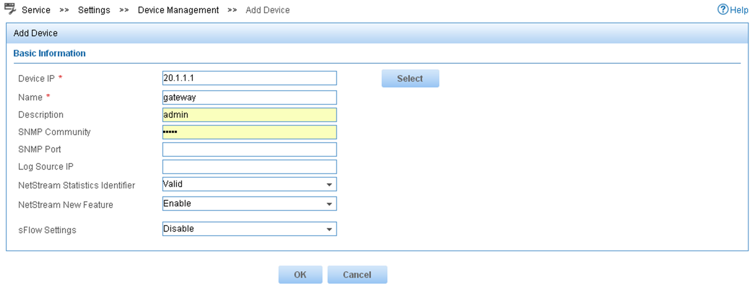
5. Click Add.
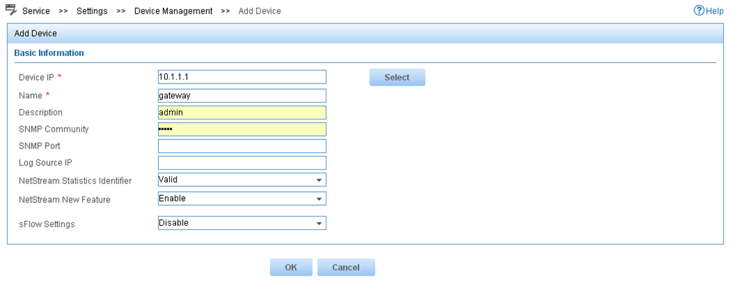
Figure 7 Adding a device
Deploying the server configuration
1. Click the Service tab.
2. From the left navigation pane, select Traffic Analysis and Audit > Settings.
3. On the Settings page that opens, click Server Management.
4. Click the Modify icon for the NTA/UBA server.
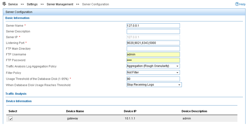
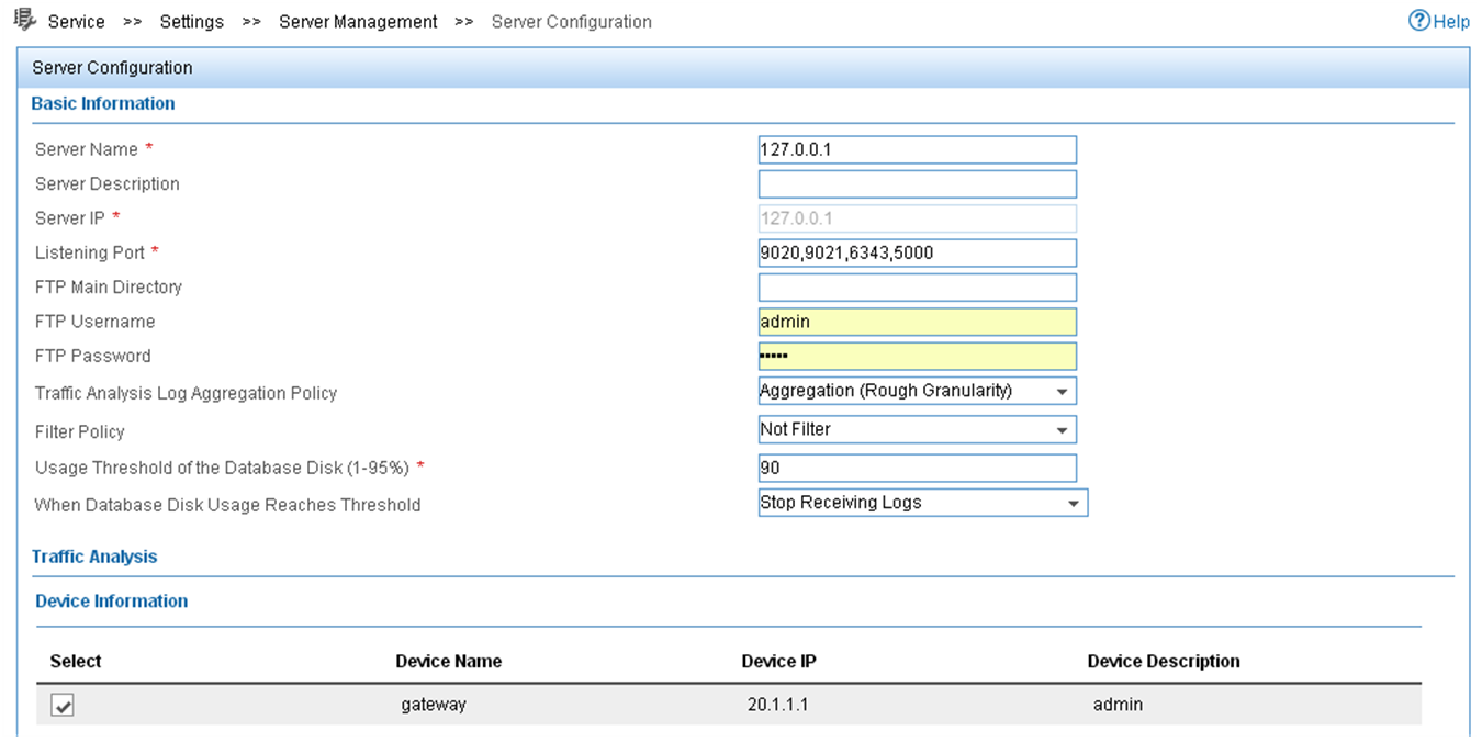
5. On the Server Configuration page shown in Figure 8, configure the server parameters and then click Deploy.
Figure 8 Deploying the server configuration
Adding a traffic analysis task
You can add multiple types of traffic analysis tasks. This example uses the interface traffic analysis task type.
To add an interface traffic analysis task:
1. Click the Service tab.
2. From the left navigation pane, select Traffic Analysis and Audit > Settings.
3. On the Settings page that opens, click Traffic Analysis Task Management.
4. Click Add. The Select Task Type page opens.
5. Select Interface and click Next. The Add Traffic Analysis Task page opens.
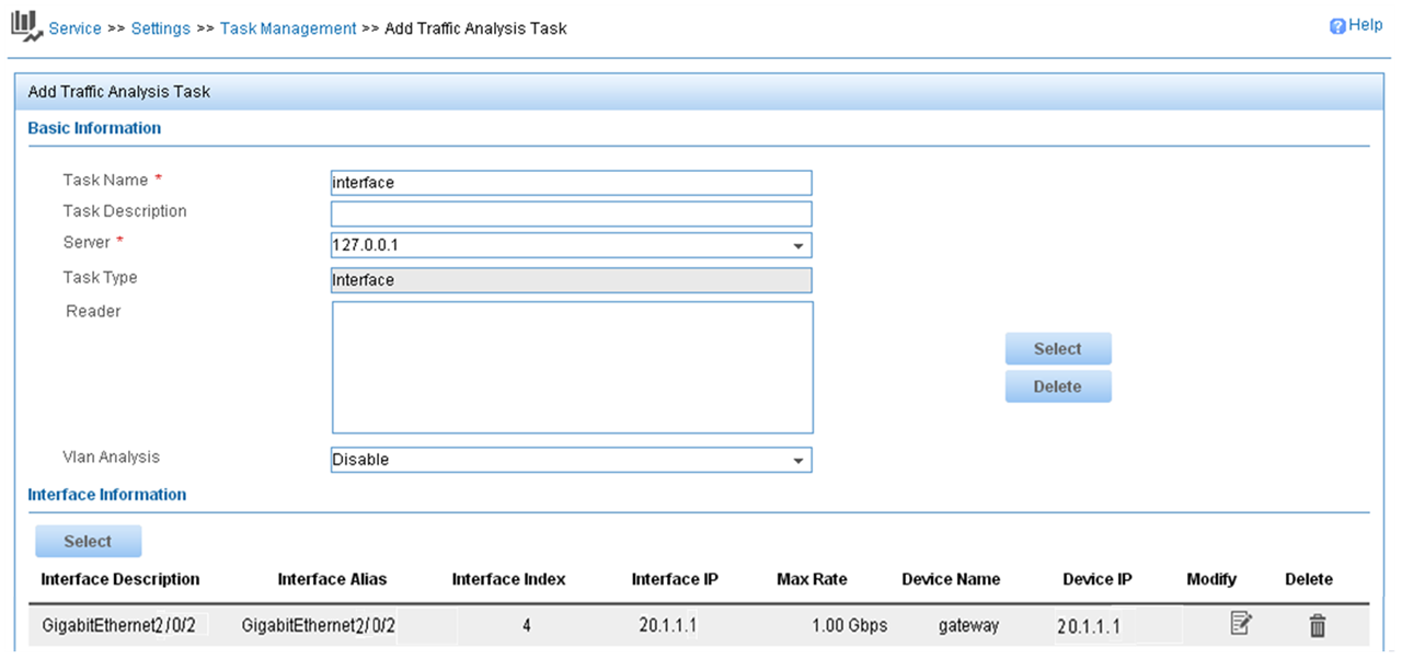
6. Configure basic information and interface information, and then click OK.
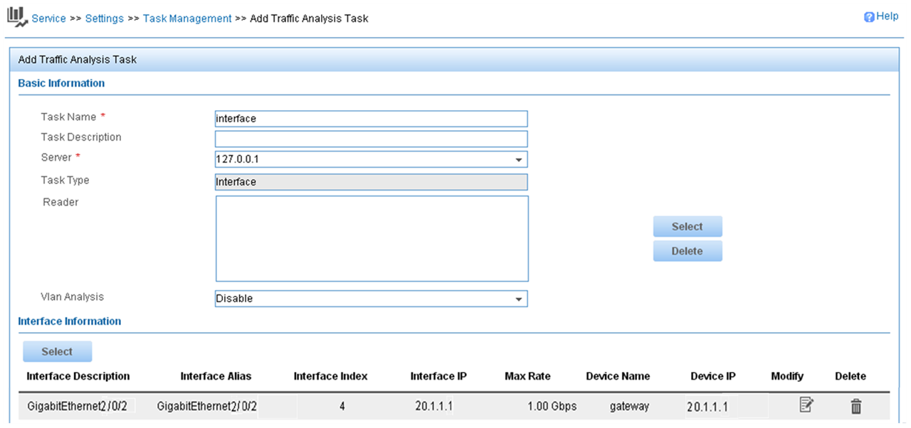
Figure 9 Adding a traffic analysis task
Verifying the configuration
1. Display IPv6 NetStream data export information.
[Gateway] display ipv6 netstream export
IPv6 export information:
Flow source interface : GigabitEthernet0/0/2
Flow destination VPN instance : Not specified
Flow destination IP address (UDP) : 22.1.1.2 (5000)
Version 9 exported flow number : 0
Version 9 exported UDP datagram number (failed) : 0 (0)
2. Display the report of the interface traffic analysis task:
a. Click the Service tab.
b. From the left navigation pane, select Traffic Analysis and Audit > Interface Traffic Analysis Task. Use either of the following methods to access the report page of interface traffic analysis task Interface:
- In the Summary List area, click the name of the interface traffic analysis task.
- On the left navigation pane, move your mouse pointer to the shortcut menu icon next to Interface Traffic Analysis Task, and then select Interface from the menu.
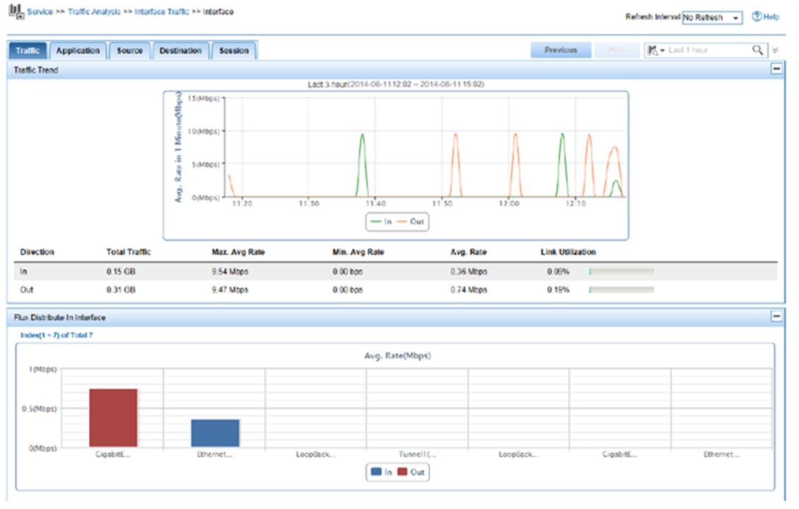
Figure 10 Interface traffic analysis

Configuration files
#
interface GigabitEthernet0/0/2
ip address 20.1.1.1 255.255.255.0
#
interface GigabitEthernet0/0/1
ipv6 netstream inbound
ipv6 netstream outbound
#
ipv6 netstream export host 22.1.1.2 5000
ipv6 netstream export source interface GigabitEthernet0/0/2
Related documentation
· Network Management and Monitoring Configuration Guide in H3C MSR1000[2600][3600] Routers Configuration Guides(V9)
· Network Management and Monitoring Command Reference in H3C MSR1000[2600][3600] Routers Command References(V9)