- Table of Contents
-
- H3C MSR1000[2600][3600] Routers Configuration Examples All-in-One-R9141-6W100
- 00-Preface
- 01-Local 802.1X Authentication Configuration Examples
- 02-RADIUS-Based 802.1X Authentication Configuration Examples
- 03-AAA Configuration Examples
- 04-ACL Configuration Examples
- 05-MPLS over ADVPN Configuration Examples
- 06-ARP Attack Protection Configuration Examples
- 07-BFD Configuration Examples
- 08-Basic BGP Configuration Examples
- 09-BGP Route Attribute-Based Route Selection Configuration Examples
- 10-EAA Monitor Policy Configuration Examples
- 11-GRE with OSPF Configuration Examples
- 12-HoVPN Configuration Examples
- 13-IGMP Snooping Configuration Examples
- 14-IGMP Configuration Examples
- 15-IPsec Configuration Examples
- 16-IPsec Digital Certificate Authentication Configuration Examples
- 17-IPv6 IS-IS Configuration Examples
- 18-IPv6 over IPv4 GRE Tunnel Configuration Examples
- 19-IPv6 over IPv4 Manual Tunnel with OSPFv3 Configuration Examples
- 20-IS-IS Configuration Examples
- 21-Combined ISATAP Tunnel and 6to4 Tunnel Configuration Examples
- 22-L2TP over IPsec Configuration Examples
- 23-Multi-Instance L2TP Configuration Examples
- 24-L2TP Multidomain Access Configuration Examples
- 25-MPLS L3VPN Configuration Examples
- 26-MPLS OAM Configuration Examples
- 27-MPLS TE Configuration Examples
- 28-Basic MPLS Configuration Examples
- 29-NAT DNS Mapping Configuration Examples
- 30-NetStream Configuration Examples
- 31-NQA Configuration Examples
- 32-NTP Configuration Examples
- 33-OSPFv3 Configuration Examples
- 34-OSPF Configuration Examples
- 35-OSPF Multi-Process Configuration Examples
- 36-OSPF Multi-Instance Configuration Examples
- 37-Portal Configuration Examples
- 38-PPP Configuration Examples
- 39-RBAC Configuration Examples
- 40-RMON Configuration Examples
- 41-IPv4 NetStream Sampling Configuration Examples
- 42-SNMP Configuration Examples
- 43-SRv6 Configuration Examples
- 44-SSH Configuration Examples
- 45-Tcl Commands Configuration Examples
- 46-VLAN Configuration Examples
- 47-VRRP Configuration Examples
- 48-VXLAN over IPsec Configuration Examples
- 49-WLAN AC Configuration Examples
- 50-Small and Medium-Sized Store Configuration Examples
- 51-Cloudnet VPN Configuration Examples
- 52-Ethernet Link Aggregation Configuration Examples
- 53-Ethernet OAM Configuration Examples
- 54-Outbound Bidirectional NAT Configuration Examples
- 55-NAT Hairpin in C-S Mode Configuration Examples
- 56-Load Sharing NAT Server Configuration Examples
- 57-BIDIR-PIM Configuration Examples
- 58-Control Plane-Based QoS Policy Configuration Examples
- 59-Scheduling a Task Configuration Examples
- 60-Client-Initiated L2TP Tunnel Configuration Examples
- 61-LAC-Auto-Initiated L2TP Tunnel Configuration Examples
- 62-Authorized ARP Configuration Examples
- 63-GTS Configuration Examples
- 64-Traffic Policing Configuration Examples
- 65-Traffic Accounting Configuration Examples
- 66-Mobile Communication Modem Management Configuration Examples
- 67-Port Isolation Configuration Examples
- 68-PBR Configuration Examples
- 69-TFTP Client Software Upgrade Configuration Examples
- 70-FTP Client Software Upgrade Configuration Examples
- 71-FTP Server Software Upgrade Configuration Examples
- 72-Routing Policy Configuration Examples
- 73-Software Upgrade from the BootWare Menu Configuration Examples
- 74-Mirroring Configuration Examples
- Related Documents
-
| Title | Size | Download |
|---|---|---|
| 48-VXLAN over IPsec Configuration Examples | 109.86 KB |
VXLAN over IPsec Configuration Examples
Copyright © 2024 New H3C Technologies Co., Ltd. All rights reserved.
No part of this manual may be reproduced or transmitted in any form or by any means without prior written consent of New H3C Technologies Co., Ltd.
Except for the trademarks of New H3C Technologies Co., Ltd., any trademarks that may be mentioned in this document are the property of their respective owners.
The information in this document is subject to change without notice.
Introduction
The following information provides VXLAN over IPsec configuration examples for the router.
Prerequisites
The following information applies to Comware 9-based router. Procedures and information in the examples might be slightly different depending on the software or hardware version of the routers.
The configuration examples were created and verified in a lab environment, and all the devices were started with the factory default configuration. When you are working on a live network, make sure you understand the potential impact of every command on your network.
The following information is provided based on the assumption that you have basic knowledge of IPsec and VXLAN.
Example: Configuring VXLAN over IPsec
Network configuration
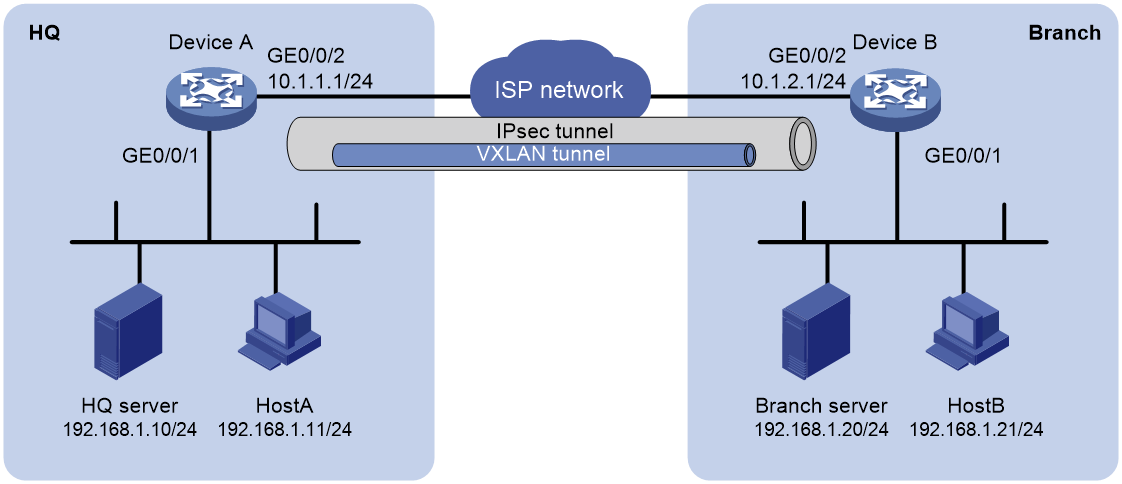
As shown in Figure 1, HQ gateway Device A and branch gateway Device B transmit data to each other through a VXLAN tunnel. Use IPsec to encrypt the data passing through the VXLAN tunnel.
Analysis
· To establish a Layer 2 interconnect between the HQ and branch, you must complete VXLAN-related configurations on Device A and Device B.
· To use IPsec to encrypt data passing through the VXLAN tunnel, define the IPsec-protected data flows on both Device A and Device B.
· To establish an IPsec tunnel between the HQ and the branch, complete IKE and IPsec configurations on Device A and Device B.
Software versions used
This configuration example was created and verified on R9141P16 of the MSR2630E-X1 device.
Restrictions and guidelines
Before starting the configuration, make sure IPv4 packets can be forwarded at Layer 3 between GE1/0/2 of HQ gateway Device A and GE1/0/2 of branch gateway Device B.
Procedures
Configuring Device A
1. Configure interface GigabitEthernet 1/0/2:
# Assign an IP address to interface GigabitEthernet 1/0/2.
<DeviceA> system
[DeviceA] interface gigabitethernet 1/0/2
[DeviceA-GigabitEthernet1/0/2] ip address 10.1.1.1 255.255.255.0
[DeviceA-GigabitEthernet1/0/2] quit
2. Configure VXLAN:
# Create VXLAN tunnel interface Tunnel 1.
[DeviceA] interface tunnel 1 mode vxlan
# Specify the source address of the tunnel as the IP address of GigabitEthernet 1/0/2.
[DeviceA-Tunnel1] source 10.1.1.1
# Specify the destination address of the tunnel as the IP address of GigabitEthernet 1/0/2.
[DeviceA-Tunnel1] destination 10.1.2.1
[DeviceA-Tunnel1] quit
# Enable L2VPN.
[DeviceA] l2vpn enable
# Create VSI instance 1 and VXLAN 1.
[DeviceA] vsi 1
[DeviceA-vsi-1] vxlan 1
# Assign Tunnel 1 to VXLAN 1.
[DeviceA-vsi-1-vxlan-1] tunnel 1
[DeviceA-vsi-1-vxlan-1] quit
[DeviceA-vsi-1] quit
# Map interface GigabitEthernet 1/0/1, which connects to the HQ server, to VSI instance 1.
[DeviceA] interface gigabitethernet 1/0/1
[DeviceA-GigabitEthernet1/0/1] xconnect vsi 1
[DeviceA-GigabitEthernet1/0/1] quit
3. Configure an ACL:
[DeviceA] acl advanced 3100
[DeviceA-acl-adv-3100] rule 0 permit ip source 10.1.1.1 0 destination 10.1.2.1 0
[DeviceA-acl-adv-3100] quit
4. Configure an IPsec transform set:
# Create IPsec transform set 1.
[DeviceA] ipsec transform-set 1
# Specify the encryption and authentication algorithms as DES-CBC and HMAC-MD5, respectively.
[DeviceA-ipsec-transform-set-1] esp encryption-algorithm des-cbc
[DeviceA-ipsec-transform-set-1] esp authentication-algorithm md5
[DeviceA-ipsec-transform-set-1] quit
5. Configure an IKE keychain:
# Create an IKE keychain named 1.
[DeviceA] ike keychain 1
# Set the pre-shared key to be used for IKE negotiation with peer 10.1.2.1 to 123456.
[DeviceA-ike-keychain-1] pre-shared-key address 10.1.2.1 255.255.255.255 key simple 123456
[DeviceA-ike-keychain-1] quit
6. Configure an IKE profile:
# Create an IKE profile named 1.
[DeviceA] ike profile 1
# Specify IKE keychain 1 for the IKE profile.
[DeviceA-ike-profile-1] keychain 1
# Configure the local ID with the identity type as IP address and the value as 10.1.1.1.
[DeviceA-ike-profile-1] local-identity address 10.1.1.1
# Configure the peer ID as IP address 10.1.2.1/32.
[DeviceA-ike-profile-1] match remote identity address 10.1.2.1 255.255.255.255
[DeviceA-ike-profile-1] quit
7. Configure an IPsec policy:
# Create an IKE-based IPsec policy entry. Specify the policy name as 1 and set the sequence number to 1.
[DeviceA] ipsec policy 1 1 isakmp
# Specify IPsec transform set 1 for the IPsec policy.
[DeviceA-ipsec-policy-isakmp-1-1] transform-set 1
# Specify ACL 3100 to identify the traffic to be protected.
[DeviceA-ipsec-policy-isakmp-1-1] security acl 3100
# Specify local IP address 10.1.1.1 for the IPsec tunnel.
[DeviceA-ipsec-policy-isakmp-1-1] local-address 10.1.1.1
# Specify remote IP address 10.1.2.1 for the IPsec tunnel.
[DeviceA-ipsec-policy-isakmp-1-1] remote-address 10.1.2.1
# Specify IKE profile 1 for the IPsec policy.
[DeviceA-ipsec-policy-isakmp-1-1] ike-profile 1
[DeviceA-ipsec-policy-isakmp-1-1] quit
8. Apply the IPsec policy to GigabitEthernet 1/0/2:
# Apply IPsec policy 1 to GigabitEthernet 1/0/2.
[DeviceA] interface gigabitethernet 1/0/2
[DeviceA-GigabitEthernet1/0/2] ipsec apply policy 1
[DeviceA-GigabitEthernet1/0/2] quit
Configuring Device B
1. Configure interface GigabitEthernet 1/0/2:
# Assign an IP address to interface GigabitEthernet 1/0/2.
<DeviceB> system
[DeviceB] interface gigabitethernet 1/0/2
[DeviceB-GigabitEthernet1/0/2] ip address 10.1.2.1 255.255.255.0
[DeviceB-GigabitEthernet1/0/2] quit
2. Configure VXLAN:
# Create VXLAN tunnel interface Tunnel 1.
[DeviceB] interface tunnel 1 mode vxlan
# Specify the source address of the tunnel as the IP address of GigabitEthernet 1/0/2, 10.1.2.1.
[DeviceB-Tunnel1] source 10.1.2.1
# Specify the destination address of the tunnel as the IP address of GigabitEthernet 1/0/2, 10.1.1.1.
[DeviceB-Tunnel1] destination 10.1.1.1
[DeviceB-Tunnel1] quit
# Enable L2VPN.
[DeviceB] l2vpn enable
# Create VSI instance 1 and VXLAN 1.
[DeviceB] vsi 1
[DeviceB-vsi-1] vxlan 1
# Assign Tunnel 1 to VXLAN 1.
[DeviceB-vsi-1-vxlan-1] tunnel 1
[DeviceB-vsi-1-vxlan-1] quit
[DeviceB-vsi-1] quit
# Map interface GigabitEthernet 1/0/1, which connects to the branch server, to VSI instance 1.
[DeviceB] interface gigabitethernet 1/0/1
[DeviceB-GigabitEthernet1/0/1] xconnect vsi 1
[DeviceB-GigabitEthernet1/0/1] quit
3. Configure an ACL:
# Create ACL 3100 to define the data flow that requires IPsec protection from the VXLAN tunnel source address 10.1.2.1 to the VXLAN tunnel destination address 10.1.1.1.
[DeviceB] acl advanced 3100
[DeviceB-acl-adv-3100] rule 0 permit ip source 10.1.2.1 0 destination 10.1.1.1 0
[DeviceB-acl-adv-3100] quit
4. Configure an IPsec transform set:
# Create IPsec transform set 1.
[DeviceB] ipsec transform-set 1
# Specify the encryption and authentication algorithms as DES-CBC and HMAC-MD5, respectively.
[DeviceB-ipsec-transform-set-1] esp encryption-algorithm des-cbc
[DeviceB-ipsec-transform-set-1] esp authentication-algorithm md5
[DeviceB-ipsec-transform-set-1] quit
5. Configure an IKE keychain:
# Create an IKE keychain named 1.
[DeviceB] ike keychain 1
# Set the pre-shared key to be used for IKE negotiation with peer 10.1.1.1 to 123456.
[DeviceB-ike-keychain-1] pre-shared-key address 10.1.1.1 255.255.255.255 key simple 123456
[DeviceB-ike-keychain-1] quit
6. Configure an IKE profile:
# Create an IKE profile named 1.
[DeviceB] ike profile 1
# Specify IKE keychain 1 for the IKE profile.
[DeviceB-ike-profile-1] keychain 1
# Configure the local ID as IP address 10.1.2.1.
[DeviceB-ike-profile-1] local-identity address 10.1.2.1
# Configure the peer ID as IP address 10.1.1.1/32.
[DeviceB-ike-profile-1] match remote identity address 10.1.1.1 255.255.255.255
[DeviceB-ike-profile-1] quit
7. Configure an IPsec policy:
# Create an IKE-based IPsec policy entry. Specify the policy name as 1 and set the sequence number to 1.
[DeviceB] ipsec policy 1 1 isakmp
# Specify IPsec transform set 1 for the IPsec policy.
[DeviceB-ipsec-policy-isakmp-1-1] transform-set 1
# Specify ACL 3100 to identify the traffic to be protected.
[DeviceB-ipsec-policy-isakmp-1-1] security acl 3100
# Specify local IP address 10.1.2.1 for the IPsec tunnel.
[DeviceB-ipsec-policy-isakmp-1-1] local-address 10.1.2.1
# Specify remote IP address 10.1.1.1 for the IPsec tunnel.
[DeviceB-ipsec-policy-isakmp-1-1] remote-address 10.1.1.1
# Specify IKE profile 1 for the IPsec policy.
[DeviceB-ipsec-policy-isakmp-1-1] ike-profile 1
[DeviceB-ipsec-policy-isakmp-1-1] quit
# Apply IPsec policy 1 to GigabitEthernet 1/0/2.
[DeviceB] interface gigabitethernet 1/0/2
[DeviceB-GigabitEthernet1/0/2] ipsec apply policy 1
[DeviceB-GigabitEthernet1/0/2] quit
Verifying the configuration
# Initiate a connection from Host B to the HQ server to trigger IKE negotiation. Verify that you can successfully ping 192.168.1.10 from 192.168.1.21 after the IPsec tunnel is successfully established.
<HostB> ping 192.168.1.10
Ping 192.168.1.10 (192.168.1.10): 56 data bytes, press CTRL_C to break
Request time out
56 bytes from 192.168.1.10: icmp_seq=1 ttl=255 time=2.000 ms
56 bytes from 192.168.1.10: icmp_seq=2 ttl=255 time=1.000 ms
56 bytes from 192.168.1.10: icmp_seq=3 ttl=255 time=2.000 ms
56 bytes from 192.168.1.10: icmp_seq=4 ttl=255 time=2.000 ms
--- Ping statistics for 192.168.1.10 ---
5 packet(s) transmitted, 4 packet(s) received, 20.0% packet loss
round-trip min/avg/max/std-dev = 1.000/1.750/2.000/0.433 ms
# Execute the display ike sa command to view the IKE SA on Device A.
<DeviceA> display ike sa
Connection-ID Remote Flag DOI
------------------------------------------------------------------------------------
6 10.1.2.1/500 RD IPsec
Flags:
RD--READY RL--REPLACED FD-FADING RK-REKEY
# Execute the display ipsec sa command to view IPsec SA information on Device A.
<DeviceA> display ipsec sa
-------------------------------
Interface: GigabitEthernet1/0/2
-------------------------------
-----------------------------
IPsec policy: 1
Sequence number: 1
Mode: ISAKMP
-----------------------------
Tunnel id: 0
Encapsulation mode: tunnel
Perfect Forward Secrecy:
Inside VPN:
Extended Sequence Numbers enable: N
Traffic Flow Confidentiality enable: N
Transmitting entity: Responder
Path MTU: 1444
Tunnel:
local address/port: 10.1.1.1/500
remote address/port: 10.1.2.1/500
Flow:
sour addr: 10.1.1.1/255.255.255.255 port: 0 protocol: ip
dest addr: 10.1.2.1/255.255.255.255 port: 0 protocol: ip
[Inbound ESP SAs]
SPI: 1526547107 (0x5afd42a3)
Connection ID: 124554051585
Transform set: ESP-ENCRYPT-DES-CBC ESP-AUTH-MD5
SA duration (kilobytes/sec): 1843200/3600
SA remaining duration (kilobytes/sec): 1843199/3314
Max received sequence-number: 5
Anti-replay check enable: Y
Anti-replay window size: 64
UDP encapsulation used for NAT traversal: N
Status: Active
[Outbound ESP SAs]
SPI: 314817206 (0x12c3bab6)
Connection ID: 124554051584
Transform set: ESP-ENCRYPT-DES-CBC ESP-AUTH-MD5
SA duration (kilobytes/sec): 1843200/3600
SA remaining duration (kilobytes/sec): 1843199/3314
Max sent sequence-number: 5
UDP encapsulation used for NAT traversal: N
Status: Active
# Execute the display interface tunnel 1 command to view information about the traffic transmitted through the VXLAN tunnel on Device A.
<DeviceA> display interface Tunnel 1
Tunnel1
Current state: UP
Line protocol state: UP
Description: Tunnel1 Interface
Bandwidth: 64 kbps
Maximum transmission unit: 1300
Internet protocol processing: Disabled
Output queue - Urgent queuing: Size/Length/Discards 0/1024/0
Output queue - Protocol queuing: Size/Length/Discards 0/500/0
Output queue - FIFO queuing: Size/Length/Discards 0/75/0
Last clearing of counters: Never
Tunnel source 10.1.1.1, destination 10.1.2.1
Tunnel protocol/transport UDP_VXLAN/IP
Last 300 seconds input rate: 3 bytes/sec, 24 bits/sec, 0 packets/sec
Last 300 seconds output rate: 3 bytes/sec, 24 bits/sec, 0 packets/sec
Input: 92 packets, 7525 bytes, 0 drops
Output: 94 packets, 7274 bytes, 0 drops
# Initiate a connection from Host A to the branch server to verify the connectivity. (Details not shown.)
Configuration files
· Device A:
#
l2vpn enable
#
vsi 1
vxlan 1
tunnel 1
#
interface GigabitEthernet1/0/1
port link-mode route
xconnect vsi 1
#
interface GigabitEthernet1/0/2
port link-mode route
ip address 10.1.1.1 255.255.255.0
ipsec apply policy 1
#
interface Tunnel1 mode vxlan
source 10.1.1.1
destination 10.1.2.1
#
acl advanced 3100
rule 0 permit ip source 10.1.1.1 0 destination 10.1.2.1 0
#
ipsec transform-set 1
esp encryption-algorithm des-cbc
esp authentication-algorithm md5
#
ipsec policy 1 1 isakmp
transform-set 1
security acl 3100
local-address 10.1.1.1
remote-address 10.1.2.1
ike-profile 1
#
ike profile 1
keychain 1
local-identity address 10.1.1.1
match remote identity address 10.1.2.1 255.255.255.255
#
ike keychain 1
pre-shared-key address 10.1.2.1 255.255.255.255 key cipher $c$3$nWZsiVDLZOBOD4Vx7wrVutbEj5VbQIoURQ==
#
return
· Device B:
#
l2vpn enable
#
vsi 1
vxlan 1
tunnel 1
#
interface GigabitEthernet1/0/1
port link-mode route
xconnect vsi 1
#
interface GigabitEthernet1/0/2
port link-mode route
ip address 10.1.2.1 255.255.255.0
ipsec apply policy 1
#
interface Tunnel1 mode vxlan
source 10.1.2.1
destination 10.1.1.1
#
acl advanced 3100
rule 0 permit ip source 10.1.2.1 0 destination 10.1.1.1 0
#
ipsec transform-set 1
esp encryption-algorithm des-cbc
esp authentication-algorithm md5
#
ipsec policy 1 1 isakmp
transform-set 1
security acl 3100
local-address 10.1.2.1
remote-address 10.1.1.1
ike-profile 1
#
ike profile 1
keychain 1
local-identity address 10.1.2.1
match remote identity address 10.1.1.1 255.255.255.255
#
ike keychain 1
pre-shared-key address 10.1.1.1 255.255.255.255 key cipher $c$3$nFvmDw8+uUDHgvYTW3FdZoijFc0jH6C9jQ==
#
return
Related documentation
· IP Tunneling and Security VPN Configuration Guide in H3C MSR1000[2600][3600] Routers Configuration Guides (V9)
· VXLAN Configuration Guide in H3C MSR1000[2600][3600] Routers Configuration Guides (V9)
· IPsec Command Reference and VXLAN Command Reference in H3C MSR1000[2600][3600] Routers Command References (V9)
· VXLAN Command Reference in H3C MSR1000[2600][3600] Routers Command References (V9)