- Table of Contents
-
- H3C MSR1000[2600][3600] Routers Configuration Examples All-in-One-R9141-6W100
- 00-Preface
- 01-Local 802.1X Authentication Configuration Examples
- 02-RADIUS-Based 802.1X Authentication Configuration Examples
- 03-AAA Configuration Examples
- 04-ACL Configuration Examples
- 05-MPLS over ADVPN Configuration Examples
- 06-ARP Attack Protection Configuration Examples
- 07-BFD Configuration Examples
- 08-Basic BGP Configuration Examples
- 09-BGP Route Attribute-Based Route Selection Configuration Examples
- 10-EAA Monitor Policy Configuration Examples
- 11-GRE with OSPF Configuration Examples
- 12-HoVPN Configuration Examples
- 13-IGMP Snooping Configuration Examples
- 14-IGMP Configuration Examples
- 15-IPsec Configuration Examples
- 16-IPsec Digital Certificate Authentication Configuration Examples
- 17-IPv6 IS-IS Configuration Examples
- 18-IPv6 over IPv4 GRE Tunnel Configuration Examples
- 19-IPv6 over IPv4 Manual Tunnel with OSPFv3 Configuration Examples
- 20-IS-IS Configuration Examples
- 21-Combined ISATAP Tunnel and 6to4 Tunnel Configuration Examples
- 22-L2TP over IPsec Configuration Examples
- 23-Multi-Instance L2TP Configuration Examples
- 24-L2TP Multidomain Access Configuration Examples
- 25-MPLS L3VPN Configuration Examples
- 26-MPLS OAM Configuration Examples
- 27-MPLS TE Configuration Examples
- 28-Basic MPLS Configuration Examples
- 29-NAT DNS Mapping Configuration Examples
- 30-NetStream Configuration Examples
- 31-NQA Configuration Examples
- 32-NTP Configuration Examples
- 33-OSPFv3 Configuration Examples
- 34-OSPF Configuration Examples
- 35-OSPF Multi-Process Configuration Examples
- 36-OSPF Multi-Instance Configuration Examples
- 37-Portal Configuration Examples
- 38-PPP Configuration Examples
- 39-RBAC Configuration Examples
- 40-RMON Configuration Examples
- 41-IPv4 NetStream Sampling Configuration Examples
- 42-SNMP Configuration Examples
- 43-SRv6 Configuration Examples
- 44-SSH Configuration Examples
- 45-Tcl Commands Configuration Examples
- 46-VLAN Configuration Examples
- 47-VRRP Configuration Examples
- 48-VXLAN over IPsec Configuration Examples
- 49-WLAN AC Configuration Examples
- 50-Small and Medium-Sized Store Configuration Examples
- 51-Cloudnet VPN Configuration Examples
- 52-Ethernet Link Aggregation Configuration Examples
- 53-Ethernet OAM Configuration Examples
- 54-Outbound Bidirectional NAT Configuration Examples
- 55-NAT Hairpin in C-S Mode Configuration Examples
- 56-Load Sharing NAT Server Configuration Examples
- 57-BIDIR-PIM Configuration Examples
- 58-Control Plane-Based QoS Policy Configuration Examples
- 59-Scheduling a Task Configuration Examples
- 60-Client-Initiated L2TP Tunnel Configuration Examples
- 61-LAC-Auto-Initiated L2TP Tunnel Configuration Examples
- 62-Authorized ARP Configuration Examples
- 63-GTS Configuration Examples
- 64-Traffic Policing Configuration Examples
- 65-Traffic Accounting Configuration Examples
- 66-Mobile Communication Modem Management Configuration Examples
- 67-Port Isolation Configuration Examples
- 68-PBR Configuration Examples
- 69-TFTP Client Software Upgrade Configuration Examples
- 70-FTP Client Software Upgrade Configuration Examples
- 71-FTP Server Software Upgrade Configuration Examples
- 72-Routing Policy Configuration Examples
- 73-Software Upgrade from the BootWare Menu Configuration Examples
- 74-Mirroring Configuration Examples
- Related Documents
-
| Title | Size | Download |
|---|---|---|
| 23-Multi-Instance L2TP Configuration Examples | 94.71 KB |
Multi-Instance L2TP Configuration Examples
Copyright © 2024 New H3C Technologies Co., Ltd. All rights reserved.
No part of this manual may be reproduced or transmitted in any form or by any means without prior written consent of New H3C Technologies Co., Ltd.
Except for the trademarks of New H3C Technologies Co., Ltd., any trademarks that may be mentioned in this document are the property of their respective owners.
The information in this document is subject to change without notice.
Introduction
The following information provides multi-instance L2TP configuration examples for the router.
Prerequisites
The following information applies to Comware 9-based router. Procedures and information in the examples might be slightly different depending on the software or hardware version of the routers.
The configuration examples were created and verified in a lab environment, and all the devices were started with the factory default configuration. When you are working on a live network, make sure you understand the potential impact of every command on your network.
The following information is provided based on the assumption that you have basic knowledge of L2TP.
Example: Configuring multi-instance L2TP
Network configuration
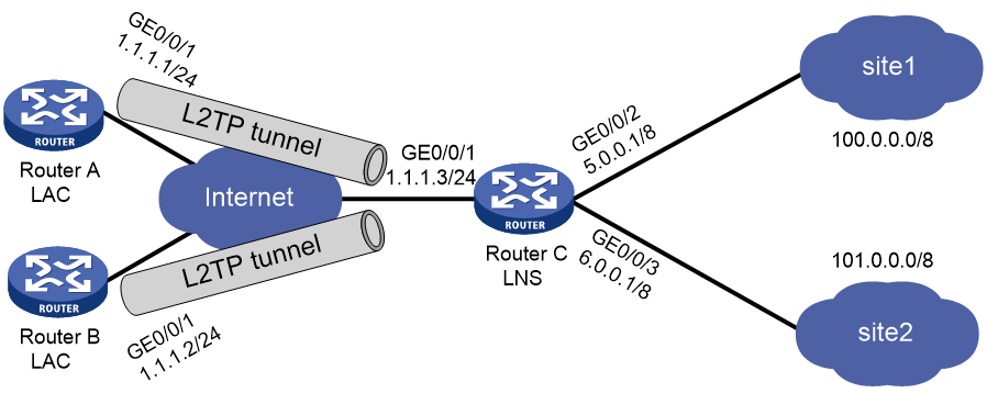
As shown in Figure 1, multiple enterprises share Router C as an LNS, and different enterprise users connect to Router A and Router B separately to communicate with their respective headquarters, Site 1 and Site 2. Configure multi-instance L2TP on Router C so that it can provide L2TP access services to Router A and Router B at the same time. In this way, users from different enterprises can remotely access their respective internal enterprise networks.
Software versions used
This configuration example was created and verified on R9141P16 of the MSR2630E-X1 device.
Procedures
Configuring Router C
# Enable L2TP globally.
<RouterC> system-view
[RouterC] l2tp enable
# Configure a local user and set the password.
[RouterC] local-user 1 class network
[RouterC-luser-network-1] password simple 1234
[RouterC-luser-network-1] service-type ppp
[RouterC-luser-network-1] quit
[RouterC] local-user 2 class network
[RouterC-luser-network-2] password simple 1234
[RouterC-luser-network-2] service-type ppp
[RouterC-luser-network-2] quit
# Configure VPN instances vpn1 and vpn2.
[RouterC] ip vpn-instance vpn1
[RouterC-vpn-instance-vpn1] route-distinguisher 100:1
[RouterC-vpn-instance-vpn1] vpn-target 100:1 import-extcommunity [RouterC-vpn-instance-vpn1] vpn-target 100:1 export-extcommunity
[RouterC-vpn-instance-vpn1] quit
[[RouterC] ip vpn-instance vpn2
[RouterC-vpn-instance-vpn2] route-distinguisher 200:1
[RouterC-vpn-instance-vpn2] vpn-target 200:1 import-extcommunity
[RouterC-vpn-instance-vpn2] vpn-target 200:1 export-extcommunity
[RouterC-vpn-instance-vpn2] quit
# Configure address pools.
[RouterC] ip pool 1 100.0.0.2 100.0.0.100
[RouterC] ip pool 2 101.0.0.2 101.0.0.100
# Create VT interface 1.
[RouterC] interface virtual-template 1
# Configure the VT interface to use PAP for authenticating the peer.
[RouterC-Virtual-Template1] ppp authentication-mode pap
# Configure the interface to allocate addresses from address pool 1 to clients.
[RouterC-Virtual-Template1] remote address pool 1
# Bind the VT interface to VPN instance vpn1.
[RouterC-Virtual-Template1] ip binding vpn-instance vpn1
[RouterC-Virtual-Template1] ip address 100.0.0.1 8
[RouterC-Virtual-Template1] quit
# Create VT interface 2.
[RouterC] interface virtual-template 2
# Configure the VT interface to use PAP for authenticating the peer.
[RouterC-Virtual-Template2] ppp authentication-mode pap
# Configure the interface to allocate addresses from address pool 2 to clients.
[RouterC-Virtual-Template2] remote address pool 2
# Bind the VT interface to VPN instance vpn2.
[RouterC-Virtual-Template2] ip binding vpn-instance vpn2
[RouterC-Virtual-Template2] ip address 101.0.0.1 8
[RouterC-Virtual-Template2] quit
# Create L2TP group 1 in LNS mode.
[RouterC] l2tp-group 1 mode lns
# Configure the local tunnel name as lns-A on the LNS and specify VT interface 1 for receiving calls from the peer named lac-A.
[RouterC-l2tp1] tunnel name lns-A
[RouterC-l2tp1] undo tunnel authentication
[RouterC-l2tp1] allow l2tp virtual-template 1 remote lac-A
[RouterC-l2tp1] quit
# Create L2TP group 1 in LNS mode.
[RouterC] l2tp-group 2 mode lns
# Configure the local tunnel name as lns-B on the LNS and specify VT interface 2 for receiving calls from the peer named lac-B.
[RouterC-l2tp2] tunnel name lns-B
[RouterC-l2tp2] undo tunnel authentication
[RouterC-l2tp2] allow l2tp virtual-template 2 remote lac-B
[RouterC-l2tp2] quit
# Assign IP addresses to interfaces and bind interfaces to VPN instances.
[RouterC] interface gigabitethernet 1/0/1
[RouterC-GigabitEthernet1/0/1] ip address 1.1.1.3 24
[RouterC-GigabitEthernet1/0/1] quit
[RouterC] interface gigabitethernet 0/0/2
[RouterC-GigabitEthernet0/0/2] ip binding vpn-instance vpn1
[RouterC-GigabitEthernet0/0/2] ip address 5.0.0.1 8
[RouterC-GigabitEthernet0/0/2] quit
[RouterC] interface gigabitethernet 0/0/3
[RouterC-GigabitEthernet0/0/3] ip binding vpn-instance vpn2
[RouterC-GigabitEthernet0/0/3] ip address 6.0.0.1 8
[RouterC-GigabitEthernet0/0/3] quit
Configuring Router A
# Enable L2TP globally.
<RouterA> system-view
[RouterA] l2tp enable
# Configure an L2TP group.
[RouterA] l2tp-group 1 mode lac
# Configure the local tunnel name as lac-A on the LAC and specify LNS IP address 1.1.1.3.
[RouterA-l2tp1] tunnel name lac-A
[RouterA-l2tp1] undo tunnel authentication
[RouterA-l2tp1] lns-ip 1.1.1.3
[RouterA-l2tp1] quit
# Create a virtual-PPP interface. On the interface, configure the PPP username as 1 and password as 1234, and configure the PPP authentication mode as PAP.
[RouterA] interface virtual-PPP 1
[RouterA-Virtual-PPP1] ip address ppp-negotiate
[RouterA-Virtual-PPP1] ppp pap local-user 1 password simple 1234
[RouterA-Virtual-PPP1] quit
# Assign an IP address to interface GigabitEthernet 1/0/1.
[RouterA] interface gigabitethernet 1/0/1
[RouterA-GigabitEthernet1/0/1] ip address 1.1.1.1 24
[RouterA-GigabitEthernet1/0/1] quit
# Configure a private network route, so that the packets to the HQ of the company are forwarded through an L2TP tunnel.
[RouterA] ip route-static 5.0.0.0 8 Virtual-PPP 1
# Trigger the LAC to automatically establish an L2TP tunnel.
[RouterA] interface virtual-PPP 1
[RouterA-Virtual-PPP1] l2tp-auto-client l2tp-group 1
[RouterA-Virtual-PPP1] quit
Configuring Router B
# Enable L2TP globally.
<RouterB> system-view
[RouterB] l2tp enable
# Configure an L2TP group.
[RouterB] l2tp-group 1 mode lac
# Configure the local tunnel name as lac-B on the LAC and specify LNS IP address 1.1.1.3.
[RouterB-l2tp1] tunnel name lac-B
[RouterB-l2tp1] undo tunnel authentication
[RouterB-l2tp1] lns-ip 1.1.1.3
[RouterB-l2tp1] quit
# Create a virtual-PPP interface. On the interface, configure the PPP username as 2 and password as 1234, and configure the PPP authentication mode as PAP.
[RouterB] interface virtual-PPP 1
[RouterB-Virtual-PPP1] ip address ppp-negotiate
[RouterB-Virtual-PPP1] ppp pap local-user 2 password simple 1234
[RouterB-Virtual-PPP1] quit
# Assign an IP address to interface GigabitEthernet 1/0/1.
[RouterB] interface gigabitethernet 1/0/1
[RouterB-GigabitEthernet1/0/1] ip address 1.1.1.2 24
[RouterB-GigabitEthernet1/0/1] quit
# Configure a private network route, so that the packets to the HQ of the company are forwarded through an L2TP tunnel.
[RouterB] ip route-static 6.0.0.0 8 virtual-PPP 1
# Trigger the LAC to automatically establish an L2TP tunnel.
[RouterB] interface virtual-PPP 1
[RouterB-Virtual-PPP1] l2tp-auto-client l2tp-group 1
[RouterB-Virtual-PPP1] quit
Verifying the configuration
1. Verify that an IP address in pool 1 is allocated to the virtual-PPP interface on Router A.
[RouterA] display interface brief
Brief information on interface(s) under route mode:
Link: ADM - administratively down; Stby - standby
Protocol: (s) - spoofing
Interface Link Protocol Main IP Description
Aux0 UP -- --
GE1/0/1 UP UP 1.1.1.1
GE1/0/2 ADM DOWN 11.1.1.1
InLoop0 UP UP(s) --
NULL0 UP UP(s) --
REG0 DOWN -- --
VPPP1 UP UP 100.0.0.2
2. Verify that an IP address in pool 2 is allocated to the virtual-PPP interface on Router B.
[RouterB] display interface brief
Brief information on interface(s) under route mode:
Link: ADM - administratively down; Stby - standby
Protocol: (s) - spoofing
Interface Link Protocol Main IP Description
Aux0 UP -- --
GE1/0/1 UP UP 1.1.1.2
GE1/0/2 UP UP 12.1.1.1
InLoop0 UP UP(s) --
NULL0 UP UP(s) --
REG0 DOWN -- --
VPPP1 UP UP 101.0.0.2
3. Verify that Router A can ping IP address 5.0.0.1 of Router C and the L2TP tunnel has been successfully established.
[RouterA] ping -a 100.0.0.2 5.0.0.1
Ping 5.0.0.1 (5.0.0.1): 56 data bytes, press CTRL_C to break
56 bytes from 5.0.0.1: icmp_seq=0 ttl=128 time=0.452 ms
56 bytes from 5.0.0.1: icmp_seq=1 ttl=128 time=0.625 ms
56 bytes from 5.0.0.1: icmp_seq=2 ttl=128 time=0.673 ms
56 bytes from 5.0.0.1: icmp_seq=3 ttl=128 time=0.687 ms
56 bytes from 5.0.0.1: icmp_seq=4 ttl=128 time=0.679 ms
--- Ping statistics for 5.0.0.1 ---
5 packets transmitted, 5 packets received, 0.0% packet loss
round-trip min/avg/max/std-dev = 0.452/0.623/0.687/0.088 ms
4. Verify that Router B can ping IP address 6.0.0.1 of Router C and the L2TP tunnel has been successfully established.
[RouterB] ping 6.0.0.1
Ping 6.0.0.1 (6.0.0.1): 56 data bytes, press CTRL_C to break
56 bytes from 6.0.0.1: icmp_seq=0 ttl=128 time=0.452 ms
56 bytes from 6.0.0.1: icmp_seq=1 ttl=128 time=0.625 ms
56 bytes from 6.0.0.1: icmp_seq=2 ttl=128 time=0.673 ms
56 bytes from 6.0.0.1: icmp_seq=3 ttl=128 time=0.687 ms
56 bytes from 6.0.0.1: icmp_seq=4 ttl=128 time=0.679 ms
--- Ping statistics for 6.0.0.1 ---
5 packets transmitted, 5 packets received, 0.0% packet loss
round-trip min/avg/max/std-dev = 0.452/0.623/0.687/0.088 ms
Configuration files
· Router C:
#
ip vpn-instance vpn1
route-distinguisher 100:1
vpn-target 100:1 import-extcommunity
vpn-target 100:1 export-extcommunity
#
ip vpn-instance vpn2
route-distinguisher 200:1
vpn-target 200:1 import-extcommunity
vpn-target 200:1 export-extcommunity
#
ip pool 1 100.0.0.2 100.0.0.100
ip pool 2 101.0.0.2 101.0.0.100
#
interface Virtual-Template1
ppp authentication-mode pap
remote address pool 1
ip binding vpn-instance vpn1
ip address 100.0.0.1 255.0.0.0
#
interface Virtual-Template2
ppp authentication-mode pap
remote address pool 2
ip binding vpn-instance vpn2
ip address 101.0.0.1 255.0.0.0
#
interface GigabitEthernet1/0/1
port link-mode route
combo enable copper
ip address 1.1.1.3 255.255.255.0
#
interface GigabitEthernet1/0/2
port link-mode route
ip binding vpn-instance vpn1
ip address 5.0.0.1 255.0.0.0
#
interface GigabitEthernet1/0/3
port link-mode route
ip binding vpn-instance vpn2
ip address 6.0.0.1 255.0.0.0
#
local-user 1 class network
password cipher $c$3$Wf7ut8Li9ryKmOvk53vSKPHvBQHOu8w=
service-type ppp
authorization-attribute user-role network-operator
#
local-user 2 class network
password cipher $c$3$rpUZj85qaeXDflgm1P5af58Kj/maHXM=
service-type ppp
authorization-attribute user-role network-operator
#
l2tp-group 1 mode lns
allow l2tp virtual-template 1 remote lac-A
undo tunnel authentication
tunnel name lns-A
#
l2tp-group 2 mode lns
allow l2tp virtual-template 2 remote lac-B
tunnel name lns-B
#
l2tp enable
#
· Router A:
#
interface Virtual-PPP1
ppp pap local-user 1 password cipher $c$3$CYBBKjOoTx2nLdklyFk5zUtfXOKC5f8=
ip address ppp-negotiate
l2tp-auto-client l2tp-group 1
#
interface GigabitEthernet1/0/1
port link-mode route
ip address 1.1.1.1 255.255.255.0
#
ip route-static 5.0.0.0 8 Virtual-PPP1
#
l2tp-group 1 mode lac
lns-ip 1.1.1.3
undo tunnel authentication
tunnel name lac-A
#
l2tp enable
#
· Router B:
#
interface Virtual-PPP1
ppp pap local-user 2 password cipher $c$3$w9MwmqfWlBN/bbkspWTwTE9V3Zxe6Sk=
ip address ppp-negotiate
l2tp-auto-client l2tp-group 1
#
interface GigabitEthernet1/0/1
port link-mode route
ip address 1.1.1.2 255.255.255.0
#
ip route-static 6.0.0.0 8 Virtual-PPP1
#
l2tp-group 1 mode lac
lns-ip 1.1.1.3
undo tunnel authentication
tunnel name lac-B
#
l2tp enable
#
Related documentation
· Layer 2—WAN Access Configuration Guide in H3C MSR1000[2600][3600] Routers Configuration Guides (V9)
· Layer 2—WAN Access Command Reference in H3C MSR1000[2600][3600] Routers Command References (V9)