- Table of Contents
-
- 03-CLI configuration examples (AC+fit AP)
- 01-HTTPS Login Configuration Examples
- 02-SSH Configuration Examples
- 03-License Management Configuration Examples
- 04-IPv6 URL Redirection Configuration Examples
- 05-AP Association with the AC at Layer 2 Configuration Examples
- 06-AP Association with the AC at Layer 2 (IPv6) Configuration Examples
- 07-Auto AP Configuration Examples
- 08-AP Association with the AC at Layer 3 Configuration Examples
- 09-AP Association with the AC at Layer 3 (IPv6) Configuration Examples
- 10-WEP Encryption Configuration Examples
- 11-PSK Encryption Configuration Examples
- 12-WPA3-SAE PSK Encryption Configuration Examples
- 13-WLAN Access (IPv6) Configuration Examples
- 14-Policy-Based Forwarding with Dual Gateways Configuration Examples
- 15-Scheduled Configuration Deployment by AP Group Configuration Examples
- 16-Inter-AC Roaming with Static Client VLAN Allocation Configuration Examples
- 17-Service Template and Radio Binding Configuration Examples
- 18-Scheduled WLAN Access Services Configuration Examples
- 19-Local Portal Authentication Configuration Examples
- 20-HTTPS-Based Local Portal Authentication Configuration Examples
- 21-Remote Portal Authentication Configuration Examples
- 22-Local Portal Authentication through LDAP Server Configuration Examples
- 23-Local Portal Authentication and SSID-based Authentication Page Pushing Configuration Examples
- 24-Local Portal MAC-Trigger Authentication Configuration Examples
- 25-Portal MAC-Trigger Authentication Configuration Examples
- 26-Local Forwarding Mode and Local Portal MAC-Trigger Authentication Configuration Examples
- 27-Local Portal Authentication (IPv6) Configuration Examples
- 28-Local Portal Authentication through LDAP Server (IPv6) Configuration Examples
- 29-Remote Portal Authentication (IPv6) Configuration Examples
- 30-Portal MAC-Trigger Authentication (IPv6) Configuration Example
- 31-Remote Portal Authentication with User Profile Authorization Configuration Examples
- 32-Portal Fail-Permit Configuration Examples
- 33-Local MAC Authentication Configuration Examples
- 34-MAC Authentication and PSK Authentication Configuration Examples
- 35-Remote MAC and Portal Authentication and Transparent Authentication Configuration Examples
- 36-Remote AP and Remote Portal MAC-Trigger Authentication Configuration Examples
- 37-MAC Authentication with Guest VLAN Assignment Configuration Examples
- 38-MAC Authentication with Guest VLAN Assignment (IPv6) Configuration Examples
- 39-Local MAC-Then-802.1X Authentication Configuration Examples
- 40-Local 802.1X Authentication Configuration Examples
- 41-Local RADIUS-Based 802.1X Authentication in EAP Relay Mode Configuration Examples
- 42-Remote 802.1X Authentication Configuration Examples
- 43-Remote 802.1X Authentication (IPv6) Configuration Examples
- 44-Remote 802.1X Authentication in WPA3-Enterprise Mode Configuration Examples
- 45-802.1X Authentication with ACL Assignment Through IMC Server Configuration Examples
- 46-802.1X Authentication with User Profile Assignment Through IMC Server Configuration Examples
- 47-EAD Authentication Configuration Examples
- 48-EAD Authentication (IPv6) Configuration Examples
- 49-Local Forwarding Mode and Local Portal Authentication Configuration Examples
- 50-Local Forwarding Mode Direct Portal Authentication Configuration Examples
- 51-Local Forwarding Mode Direct Portal Authentication (IPv6) Configuration Examples
- 52-Local Forwarding Configuration Examples
- 53-Remote AP Configuration Examples
- 54-WIPS Configuration Examples
- 55-WIPS Countermeasures Against All SSIDs Configuration Examples
- 56-IP Source Guard (IPv4) Configuration Examples
- 57-IP Source Guard (IPv6) Configuration Examples
- 58-IRF Setup with Members Directly Connected Configuration Examples
- 59-IRF Setup with Members Not Directly Connected Configuration Examples
- 60-IRF Setup with Members in One Chassis Configuration Examples
- 61-IRF Setup with Members in Different Chassis Configuration Examples
- 62-Dual-Link Backup Configuration Examples
- 63-Remote 802.1X Auth on AC Hierarchy Network with Dual-Link Central AC Backup Configuration Examples
- 64-Remote Portal Auth on AC Hierarchy Network with Dual-Link Central AC Backup Configuration Examples
- 65-OAuth-Based Portal MAC-Trigger Auth on Local-Forwarding Dual-Link Backup Configuration Examples
- 66-Dual-Link Backup OAuth-Based Portal Auth in Local Forwarding Configuration Examples
- 67-Dual-Link Backup Remote Portal MAC-Trigger Auth in Local Forwarding Configuration Examples
- 68-Dual-Link Backup Remote Portal and Transparent MAC Auth in Local Forwarding Configuration Examples
- 69-Dual-Link Backup Remote Portal Auth in Local Forwarding Configuration Examples
- 70-Dual-Link Backup Remote Portal and MAC Auth in Centralized Forward Configuration Examples
- 71-Dual-Link Backup Remote Portal Auth in Centralized Forwarding Configuration Examples
- 72-Dual-Link Backup Lightweight Portal Auth in Centralized Forwarding Configuration Examples
- 73-Dual-Link Backup OAuth-Based Portal Auth in Centralized Forwarding Configuration Examples
- 74-Dual-Link Backup Remote Portal MAC-Trigger Auth in Centralized Forwarding Configuration Examples
- 75-Remote 802.1X Auth on a Dual-Link AC Backup Network Configuration Examples
- 76-Remote MAC Auth on a Dual-Link AC Backup Network Configuration Examples
- 77-Remote 802.1X Authentication on an AC Hierarchy Network Configuration Examples
- 78-Remote 802.1X Authentication Configuration Examples
- 79-WLAN Probe Configuration Examples
- 80-Multicast Optimization Configuration Examples
- 81-Client Rate Limiting Configuration Examples
- 82-Inter-AC Roaming Configuration Examples
- 83-Inter-AC Roaming (IPv6) Configuration Examples
- 84-WLAN Load Balancing Configuration Examples
- 85-Static Blacklist Configuration Examples
- 86-Client Quantity Control Configuration Examples
- 87-AP License Synchronization Configuration Examples
- 88-iBeacon Management Configuration Examples
- 89-Mesh Link Establishment Between a Fit AP and a Fat AP Configuration Examples
- 90-Mesh Link Establishment Between Fit APs Configuration Examples
- 91-Auto-DFS and Auto-TPC Configuration Examples
- 92-AP Image Downloading Configuration Examples
- 93-Dual-Uplink Interfaces Configuration Guide
- 94-Internal-to-External Access Through NAT Configuration Examples
- 95-Layer 2 Static Aggregation Configuration Examples
- 96-Layer 2 Multicast Configuration Examples
- 97-Static VLAN Allocation Configuration Examples
- 98-URL Redirection Configuration Examples
- Related Documents
-
| Title | Size | Download |
|---|---|---|
| 89-Mesh Link Establishment Between a Fit AP and a Fat AP Configuration Examples | 91.57 KB |
|
|
|
H3C Access Controllers |
|
Comware 7 Mesh Link Establishment Between a Fit AP and and a Fat AP |
|
Configuration Examples |
|
|
Copyright © 2022 New H3C Technologies Co., Ltd. All rights reserved.
No part of this manual may be reproduced or transmitted in any form or by any means without prior written consent of New H3C Technologies Co., Ltd.
Except for the trademarks of New H3C Technologies Co., Ltd., any trademarks that may be mentioned in this document are the property of their respective owners.
The information in this document is subject to change without notice.
Introduction
The following information provides an example of configuring a mesh link between a fit AP and a fat AP.
Prerequisites
The following information applies to Comware 7-based access controllers and access points. Procedures and information in the examples might be slightly different depending on the software or hardware version of the access controllers and access points.
The configuration examples were created and verified in a lab environment, and all the devices were started with the factory default configuration. When you are working on a live network, make sure you understand the potential impact of every command on your network.
The following information is provided based on the assumption that you have basic knowledge of WLAN mesh.
Example: Configuring a mesh link between a fit AP and a fat AP
Network configuration
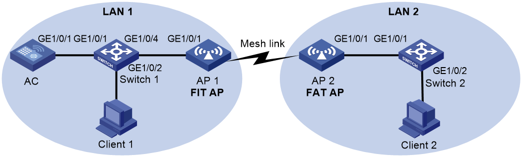
As shown in Figure 1, in centralized forwarding mode, the AC in LAN 1 is connected to Switch 1, and Switch 1 assigns an IP address to the AP and client in LAN 1 as a DHCP server. Switch 2 assigns an IP address to the client in LAN 2 as a DHCP server. Configure the devices to meet the following requirements:
· AP 1 obtains an IP address from the address pool on VLAN 10 configured on Switch 1 and comes online from the AC.
· The clients in LAN 1 and LAN 2 are assigned to different VLANs and are reachable to each other at Layer 3.
Restrictions and guidelines
· Use the serial ID labeled on the AP's rear panel to specify an AP.
· Configure GE 1/0/4 that connects Switch 1 to the AP as a trunk port, and remove the port from VLAN 1.
Procedures
Configuring Switch 1
1. Configure interfaces on Switch 1:
# Create VLAN 10 and VLAN-interface 10, and assign an IP address to the VLAN interface. The AC will use this IP address to establish a CAPWAP tunnel with the AP.
<Switch1> system-view
[Switch1] vlan 10
[Switch1-vlan10] quit
[Switch1] interface vlan-interface 10
[Switch1-Vlan-interface10] ip address 172.16.1.1 255.255.255.0
[Switch1-Vlan-interface10] quit
# Create VLAN 20 and VLAN-interface 20, and assign an IP address to the VLAN interface. This VLAN will use be used as the gateway for the clients.
[Switch1] vlan 20
[Switch1-vlan20] quit
[Switch1] interface vlan-interface 20
[Switch1-Vlan-interface20] ip address 192.168.10.1 255.255.255.0
[Switch1-Vlan-interface20] quit
# Create VLAN 30 and VLAN-interface 30, and assign an IP address to the VLAN interface. The switch will use this VLAN to communicate with the AP.
[Switch1] vlan 30
[Switch1-vlan30] quit
[Switch1] interface vlan-interface 30
[Switch1-Vlan-interface30] ip address 10.12.12.1 255.255.255.0
[Switch1-Vlan-interface30] quit
# Configure GigabitEthernet 1/0/1 that connects Switch 1 to the AC as a trunk port, and assign the port to all VLANs.
[Switch1] interface gigabitEthernet 1/0/1
[Switch1-GigabitEthernet1/0/1] port link-type trunk
[Switch1-GigabitEthernet1/0/1] port trunk permit vlan all
[Switch1-GigabitEthernet1/0/1] quit
# Configure GigabitEthernet 1/0/4 that connects Switch 1 to AP 1 as a trunk port, remove the port from VLAN 1, and assign the port to all the other VLANs.
[Switch1] interface gigabitEthernet 1/0/4
[Switch1-GigabitEthernet1/0/4] port link-type trunk
[Switch1-GigabitEthernet1/0/4] port trunk permit vlan all
[Switch1-GigabitEthernet1/0/4] undo port trunk permit vlan 1
# Set the PVID of GigabitEthernet 1/0/4 to VLAN 10.
[Switch1-GigabitEthernet1/0/4] port trunk pvid vlan 10
[Switch1-GigabitEthernet1/0/4] quit
# Assign GigabitEthernet 1/0/2 that connects Switch 1 to Client 1 to VLAN 20.
[Switch1] interface gigabitEthernet 1/0/2
[Switch1-GigabitEthernet1/0/2] port access vlan 20
[Switch1-GigabitEthernet1/0/2] quit
[Switch1] quit
2. Configure the DHCP server:
# Enable DHCP.
<Switch1> system-view
[Switch1] dhcp enable
# Specify 172.16.1.0/24 as the address range for dynamic allocation in DHCP address pool 1, and specify 172.16.1.1 as the gateway address.
[Switch1] dhcp server ip-pool 1
[Switch1-dhcp-pool-1] network 172.16.1.0 mask 255.255.255.0
[Switch1-dhcp-pool-1] gateway-list 172.16.1.1
# Exclude 172.16.1.2 from dynamic allocation.
[Switch1-dhcp-pool-1] forbidden-ip 172.16.1.2
[Switch1-dhcp-pool-1] quit
# Configure DHCP address pool 2. In the address pool, specify 192.168.10.1 as the gateway IP address, 192.168.10.0/24 as the subnet for dynamic allocation, and 192.168.10.1 as the DNS server address.
[Switch1] dhcp server ip-pool 2
[Switch1-dhcp-pool-2] network 192.168.10.0 mask 255.255.255.0
[Switch1-dhcp-pool-2] gateway-list 192.168.10.1
[Switch1-dhcp-pool-2] dns-list 192.168.10.1
[Switch1-dhcp-pool-2] quit
3. # Configure a route to the network where Client 2 resides.
[Switch1] ip route-static 192.168.20.0 255.255.255.0 10.12.12.2
Configuring the AC
1. Configure interfaces on the AC:
# Create VLAN 10 and VLAN-interface 100, and assign an IP address to the VLAN interface. The AC will use this IP address to establish a CAPWAP tunnel with the AP.
[AC] vlan 10
[AC-vlan10] quit
[AC] interface vlan-interface 10
[AC-Vlan-interface10] ip address 172.16.1.2 255.255.255.0
[AC-Vlan-interface10] quit
# Configure GigabitEthernet 1/0/1 that connects the AC to Switch 1 as a trunk port, and assign the port to all VLANs.
[AC] interface gigabitethernet 1/0/1
[AC-GigabitEthernet1/0/1] port link-type trunk
[AC-GigabitEthernet1/0/1] port trunk permit vlan all
[AC-GigabitEthernet1/0/1] quit
2. Configure a fit AP:
# Create a manual AP named ap1, and specify the AP model and serial ID.
[AC] wlan ap ap1 model WA6330
[AC-wlan-ap-ap1] serial-id 219801A23V8192E00021
# Enter the view of radio 1, specify the radio type as dot11an, and specify the channel as 36.
[AC-wlan-ap-ap1] radio 1
[AC-wlan-ap-ap1-radio-1] type dot11an
[AC-wlan-ap-ap1-radio-1] channel 36
# Enable radio 1.
[AC-wlan-ap-ap1-radio-1] radio enable
[AC-wlan-ap-ap1-radio-1] quit
[AC-wlan-ap-ap1] quit
3. Configure a mesh profile:
# Create mesh profile 1.
[AC] wlan mesh-profile 1
# Set the mesh ID to 1.
[AC-wlan-mesh-profile-1] mesh-id 1
# Set the authentication and key management (AKM) mode to sae.
[AC-wlan-mesh-profile-1] akm mode sae
# Configure simple character string meshlink as the PSK.
[AC-wlan-mesh-profile-1] preshared-key pass-phrase simple meshlink
# Enable the mesh profile.
[AC-wlan-mesh-profile-1] mesh-profile enable
[AC-wlan-mesh-profile-1] quit
# Bind radio 1 to the mesh profile.
[AC] wlan ap ap1
[AC-wlan-ap-ap1] radio 1
[AC-wlan-ap-ap1-radio-1] mesh-profile 1
4. Add the MAC address of AP 2 to the mesh peer whitelist for AP ap1.
[AC-wlan-ap-ap1-radio-1] mesh peer-mac-address 90e7-1066-e060
[AC-wlan-ap-ap1-radio-1] quit
5. Configure a WLAN-mesh interface:
# Create a WLAN-mesh interface.
[AC-wlan-ap-ap1] interface wlan-mesh 1
# Configure WLAN-mesh interface 1 as a trunk port, and assign the port to all VLANs.
[AC-wlan-ap-ap1-wlan-mesh-1] mesh-port link-type trunk
[AC-wlan-ap-ap1-wlan-mesh-1] mesh-port trunk permit vlan all
[AC-wlan-ap-ap1-wlan-mesh-1] quit
# Bind WLAN-mesh interface 1 to radio 1.
[AC-wlan-ap-ap1] radio 1
[AC-wlan-ap-ap1-radio-1] mesh-interface 1
[AC-wlan-ap-ap1-radio-1] quit
6. Editing the AP’s configuration file
# Edit the AP’s configuration file, name it map.txt and upload the configuration file to the AC.
system-view
vlan 30
quit
interface gigabitethernet 1/0/1
port link-type trunk
port trunk permit vlan all
quit
[AC-wlan-ap-ap1] map-configuration map.txt
[AC-wlan-ap-ap1] quit
Configuring Switch 2
1. Configure interfaces on Switch 2:
# Create VLAN 40 and VLAN-interface 40, and assign an IP address to the VLAN interface. This VLAN will be used for client access.
<Switch2> system-view
[Switch2] vlan 40
[Switch2-vlan40] quit
[Switch2] interface vlan-interface 40
[Switch2-Vlan-interface40] ip address 192.168.20.2 255.255.255.0
[Switch2-Vlan-interface40] quit
# Configure GigabitEthernet 1/0/1 that connects Switch 2 to the AC as a trunk port, and assign the port to all VLANs.
[Switch2] interface gigabitEthernet 1/0/1
[Switch2-GigabitEthernet1/0/1] port link-type trunk
[Switch2-GigabitEthernet1/0/1] port trunk permit vlan all
[Switch2-GigabitEthernet1/0/1] quit
# Assign GigabitEthernet1/0/2 that connects Switch 2 to Client 2 to VLAN 40.
[Switch2] interface gigabitEthernet 1/0/2
[Switch2-GigabitEthernet1/0/2] port access vlan 40
[Switch2-GigabitEthernet1/0/2] quit
2. Configure the DHCP server:
# Enable DHCP.
<Switch2> system-view
[Switch2] dhcp enable
# Specify 192.168.20.0/24 as the address range for dynamic allocation in DHCP address pool 1, and specify 192.168.20.1 as the gateway address.
[Switch2] dhcp server ip-pool 1
[Switch2-dhcp-pool-1] network 192.168.20.0 mask 255.255.255.0
[Switch2-dhcp-pool-1] gateway-list 192.168.20.1
# Exclude 192.168.20.1 from dynamic allocation.
[Switch2-dhcp-pool-1] forbidden-ip 192.168.20.1
[Switch2-dhcp-pool-1] quit
Configuring AP 2
1. Configure interfaces on AP 2:
# Create VLAN 30 and VLAN-interface 30, and assign an IP address to the VLAN interface. The AP will use this VLAN to communicate with Switch 1.
<AP2> system-view
[AP2] vlan 30
[AP2-vlan30] quit
[AP2] interface vlan-interface 30
[AP2-Vlan-interface30] ip address 10.12.12.2 255.255.255.0
[AP2-Vlan-interface30] quit
# Create VLAN 40 and VLAN-interface 20, and assign an IP address to the VLAN interface. This VLAN will be used as the gateway for the clients.
[AP2] vlan 40
[AP2-vlan40] quit
[AP2] interface vlan-interface 40
[AP2-Vlan-interface40] ip address 192.168.20.1 255.255.255.0
[AP2-Vlan-interface40] quit
2. Configure a radio interface:
# Enter the view of WLAN-Radio 1/0/1, specify the radio type as dot11an, and specify the channel as 36.
[AP2] interface wlan-radio 1/0/1
[AP2-WLAN-Radio1/0/1] type dot11an
[AP2-WLAN-Radio1/0/1] channel 36
[AP2-WLAN-Radio1/0/1] quit
3. Configure a mesh profile:
# Create mesh profile 1.
[AP2] wlan mesh-profile 1
# Set the mesh ID to 1.
[AP2-wlan-mesh-profile-1] mesh-id 1
# Set the authentication and key management (AKM) mode to sae.
[AP2-wlan-mesh-profile-1] akm mode sae
# Configure simple character string meshlink as the PSK.
[AP2-wlan-mesh-profile-1] preshared-key pass-phrase simple meshlink
# Enable the mesh profile.
[AP2-wlan-mesh-profile-1] mesh-profile enable
[AP2-wlan-mesh-profile-1] quit
# Bind WLAN-Radio 1/0/1 to the mesh profile.
[AP2] interface wlan-radio 1/0/1
[AP2-WLAN-Radio1/0/1] mesh-profile 1
4. Add the MAC address of AP 1 to the mesh peer whitelist for the fat AP.
[AP2-WLAN-Radio1/0/1] mesh peer-mac-address 542b-dea7-a8c0
[AP2-WLAN-Radio1/0/1] quit
5. Configure a WLAN-mesh interface:
# Create a WLAN-mesh interface.
[AP2] interface wlan-mesh 1
# Configure WLAN-mesh interface 1 as a trunk port, and assign the port to all VLANs.
[AP2-WLAN-Mesh1] port link-type trunk
[AP2-WLAN-Mesh1] port trunk permit vlan all
[AP2-WLAN-Mesh1] quit
# Bind WLAN-mesh interface 1 to WLAN-Radio 1/0/1.
[AP2] interface wlan-radio 1/0/1
[AP2-WLAN-Radio1/0/1] mesh-interface 1
[AP2-WLAN-Radio1/0/1] quit
6. Configure a route to the network where Client 1 resides.
[AP2] ip route-static 192.168.10.0 255.255.255.0 10.12.12.1
Verifying the configuration
1. Verify that AP 1 has been associated with the AC. If the AP is in R/M state, the AP has been associated with the AC.
<AC> display wlan ap name ap1
AP information
State : I = Idle, J = Join, JA = JoinAck, IL = ImageLoad
C = Config, DC = DataCheck, R = Run, M = Master, B = Backup
AP name APID State Model Serial ID
ap1 1 R/M WA6330 219801A23V8192E00021
2. Display mesh link information on the fat AP:
<AP2> display wlan mesh-link
Peer MAC RSSI BSSID Interface Link state Online time
542b-dea7-a8c0 81 d461-fe59-4d20 WLAN-MeshLink2 Active(an) 20h 00m 49s
3. Ping Client 2 from Client 1 to verify that they are reachable to each other.
C:\Users\system32> ping 192.168.20.3
Pinging 192.168.20.3 with 32 bytes of data:
Reply from 192.168.20.3: bytes=32 time<1ms TTL=255
Reply from 192.168.20.3: bytes=32 time<1ms TTL=255
Reply from 192.168.20.3: bytes=32 time<1ms TTL=255
Reply from 192.168.20.3: bytes=32 time<1ms TTL=255
Ping statistics for 192.168.20.3:
Packets: Sent = 4, Received = 4, Lost = 0 (0% loss),
Approximate round trip times in milli-seconds:
Minimum = 0ms, Maximum = 0ms, Average = 0ms
Configuration files
· Switch 1:
#
dhcp enable
#
vlan 10
#
vlan 20
#
vlan 30
#
dhcp server ip-pool 1
forbidden-ip 172.16.1.2
gateway-list 172.16.1.1
network 172.16.1.0 mask 255.255.255.0
#
dhcp server ip-pool 2
gateway-list 192.168.10.1
network 192.168.10.0 mask 255.255.255.0
dns-list 192.168.10.1
#
interface Vlan-interface10
ip address 172.16.1.1 255.255.255.0
#
interface Vlan-interface20
ip address 192.168.10.1 255.255.255.0
#
interface Vlan-interface30
ip address 10.12.12.1 255.255.255.0
#
interface GigabitEthernet1/0/1
port link-type trunk
port trunk permit vlan all
#
interface GigabitEthernet1/0/2
port access vlan 20
#
interface GigabitEthernet1/0/4
port link-type trunk
undo port trunk permit vlan 1
port trunk permit vlan 2 to 4094
port trunk pvid vlan 10
#
ip route-static 192.168.20.0 255.255.255.0 10.12.12.2
#
· AC:
#
wlan mesh-profile 1
mesh-id 1
akm mode sae
preshared-key pass-phrase cipher $c$3$qVXx1KuNn4FeEi3nMUkQ7A8jcIMrN8JH2AOv
mesh-profile enable
#
vlan 10
#
interface Vlan-interface10
ip address 172.16.1.2 255.255.255.0
#
interface GigabitEthernet1/0/1
port link-type trunk
port trunk permit vlan all
#
wlan ap ap1 model WA6330
serial-id 219801A23V8192E00021
map-configuration flash:/map.txt
vlan 1
interface wlan-mesh 1
mesh-port link-type trunk
mesh-port trunk permit vlan all
radio 1
type dot11an
channel 36
radio enable
mesh-profile 1
mesh-interface 1
mesh peer-mac-address 90e7-1066-e060
#
· Switch 2:
#
dhcp enable
#
vlan 40
#
dhcp server ip-pool 1
forbidden-ip 192.168.20.1
gateway-list 192.168.20.1
network 192.168.20.0 mask 255.255.255.0
#
interface Vlan-interface40
ip address 192.168.20.2 255.255.255.0
#
interface GigabitEthernet1/0/1
port link-type trunk
port trunk permit vlan all
#
interface GigabitEthernet1/0/2
port access vlan 40
#
· AP 2:
#
wlan mesh-profile 1
mesh-id 1
akm mode sae
preshared-key pass-phrase cipher $c$3$qVXx1KuNn4FeEi3nMUkQ7A8jcIMrN8JH2AOv
mesh-profile enable
#
vlan 30
#
vlan 40
#
interface Vlan-interface30
ip address 10.12.12.2 255.255.255.0
#
interface Vlan-interface40
ip address 192.168.20.1 255.255.255.0
#
interface WLAN-Radio1/0/1
mesh-profile 1
mesh-interface 1
mesh peer-mac-address 542b-dea7-a8c0
type dot11an
channel 36
#
interface WLAN-Mesh1
port link-type trunk
port trunk permit vlan all
#
ip route-static 192.168.10.0 255.255.255.0 10.12.12.1
#
Related documentation
· AP Management Command Reference in H3C Access Controllers Command References
· AP Management Configuration Guide in H3C Access Controllers Configuration Guides
· WLAN Mesh Command Reference in H3C Access Controllers Command References
· WLAN Mesh Configuration Guide in H3C Access Controllers Configuration Guides
