- Table of Contents
-
- 03-CLI configuration examples (AC+fit AP)
- 01-HTTPS Login Configuration Examples
- 02-SSH Configuration Examples
- 03-License Management Configuration Examples
- 04-IPv6 URL Redirection Configuration Examples
- 05-AP Association with the AC at Layer 2 Configuration Examples
- 06-AP Association with the AC at Layer 2 (IPv6) Configuration Examples
- 07-Auto AP Configuration Examples
- 08-AP Association with the AC at Layer 3 Configuration Examples
- 09-AP Association with the AC at Layer 3 (IPv6) Configuration Examples
- 10-WEP Encryption Configuration Examples
- 11-PSK Encryption Configuration Examples
- 12-WPA3-SAE PSK Encryption Configuration Examples
- 13-WLAN Access (IPv6) Configuration Examples
- 14-Policy-Based Forwarding with Dual Gateways Configuration Examples
- 15-Scheduled Configuration Deployment by AP Group Configuration Examples
- 16-Inter-AC Roaming with Static Client VLAN Allocation Configuration Examples
- 17-Service Template and Radio Binding Configuration Examples
- 18-Scheduled WLAN Access Services Configuration Examples
- 19-Local Portal Authentication Configuration Examples
- 20-HTTPS-Based Local Portal Authentication Configuration Examples
- 21-Remote Portal Authentication Configuration Examples
- 22-Local Portal Authentication through LDAP Server Configuration Examples
- 23-Local Portal Authentication and SSID-based Authentication Page Pushing Configuration Examples
- 24-Local Portal MAC-Trigger Authentication Configuration Examples
- 25-Portal MAC-Trigger Authentication Configuration Examples
- 26-Local Forwarding Mode and Local Portal MAC-Trigger Authentication Configuration Examples
- 27-Local Portal Authentication (IPv6) Configuration Examples
- 28-Local Portal Authentication through LDAP Server (IPv6) Configuration Examples
- 29-Remote Portal Authentication (IPv6) Configuration Examples
- 30-Portal MAC-Trigger Authentication (IPv6) Configuration Example
- 31-Remote Portal Authentication with User Profile Authorization Configuration Examples
- 32-Portal Fail-Permit Configuration Examples
- 33-Local MAC Authentication Configuration Examples
- 34-MAC Authentication and PSK Authentication Configuration Examples
- 35-Remote MAC and Portal Authentication and Transparent Authentication Configuration Examples
- 36-Remote AP and Remote Portal MAC-Trigger Authentication Configuration Examples
- 37-MAC Authentication with Guest VLAN Assignment Configuration Examples
- 38-MAC Authentication with Guest VLAN Assignment (IPv6) Configuration Examples
- 39-Local MAC-Then-802.1X Authentication Configuration Examples
- 40-Local 802.1X Authentication Configuration Examples
- 41-Local RADIUS-Based 802.1X Authentication in EAP Relay Mode Configuration Examples
- 42-Remote 802.1X Authentication Configuration Examples
- 43-Remote 802.1X Authentication (IPv6) Configuration Examples
- 44-Remote 802.1X Authentication in WPA3-Enterprise Mode Configuration Examples
- 45-802.1X Authentication with ACL Assignment Through IMC Server Configuration Examples
- 46-802.1X Authentication with User Profile Assignment Through IMC Server Configuration Examples
- 47-EAD Authentication Configuration Examples
- 48-EAD Authentication (IPv6) Configuration Examples
- 49-Local Forwarding Mode and Local Portal Authentication Configuration Examples
- 50-Local Forwarding Mode Direct Portal Authentication Configuration Examples
- 51-Local Forwarding Mode Direct Portal Authentication (IPv6) Configuration Examples
- 52-Local Forwarding Configuration Examples
- 53-Remote AP Configuration Examples
- 54-WIPS Configuration Examples
- 55-WIPS Countermeasures Against All SSIDs Configuration Examples
- 56-IP Source Guard (IPv4) Configuration Examples
- 57-IP Source Guard (IPv6) Configuration Examples
- 58-IRF Setup with Members Directly Connected Configuration Examples
- 59-IRF Setup with Members Not Directly Connected Configuration Examples
- 60-IRF Setup with Members in One Chassis Configuration Examples
- 61-IRF Setup with Members in Different Chassis Configuration Examples
- 62-Dual-Link Backup Configuration Examples
- 63-Remote 802.1X Auth on AC Hierarchy Network with Dual-Link Central AC Backup Configuration Examples
- 64-Remote Portal Auth on AC Hierarchy Network with Dual-Link Central AC Backup Configuration Examples
- 65-OAuth-Based Portal MAC-Trigger Auth on Local-Forwarding Dual-Link Backup Configuration Examples
- 66-Dual-Link Backup OAuth-Based Portal Auth in Local Forwarding Configuration Examples
- 67-Dual-Link Backup Remote Portal MAC-Trigger Auth in Local Forwarding Configuration Examples
- 68-Dual-Link Backup Remote Portal and Transparent MAC Auth in Local Forwarding Configuration Examples
- 69-Dual-Link Backup Remote Portal Auth in Local Forwarding Configuration Examples
- 70-Dual-Link Backup Remote Portal and MAC Auth in Centralized Forward Configuration Examples
- 71-Dual-Link Backup Remote Portal Auth in Centralized Forwarding Configuration Examples
- 72-Dual-Link Backup Lightweight Portal Auth in Centralized Forwarding Configuration Examples
- 73-Dual-Link Backup OAuth-Based Portal Auth in Centralized Forwarding Configuration Examples
- 74-Dual-Link Backup Remote Portal MAC-Trigger Auth in Centralized Forwarding Configuration Examples
- 75-Remote 802.1X Auth on a Dual-Link AC Backup Network Configuration Examples
- 76-Remote MAC Auth on a Dual-Link AC Backup Network Configuration Examples
- 77-Remote 802.1X Authentication on an AC Hierarchy Network Configuration Examples
- 78-Remote 802.1X Authentication Configuration Examples
- 79-WLAN Probe Configuration Examples
- 80-Multicast Optimization Configuration Examples
- 81-Client Rate Limiting Configuration Examples
- 82-Inter-AC Roaming Configuration Examples
- 83-Inter-AC Roaming (IPv6) Configuration Examples
- 84-WLAN Load Balancing Configuration Examples
- 85-Static Blacklist Configuration Examples
- 86-Client Quantity Control Configuration Examples
- 87-AP License Synchronization Configuration Examples
- 88-iBeacon Management Configuration Examples
- 89-Mesh Link Establishment Between a Fit AP and a Fat AP Configuration Examples
- 90-Mesh Link Establishment Between Fit APs Configuration Examples
- 91-Auto-DFS and Auto-TPC Configuration Examples
- 92-AP Image Downloading Configuration Examples
- 93-Dual-Uplink Interfaces Configuration Guide
- 94-Internal-to-External Access Through NAT Configuration Examples
- 95-Layer 2 Static Aggregation Configuration Examples
- 96-Layer 2 Multicast Configuration Examples
- 97-Static VLAN Allocation Configuration Examples
- 98-URL Redirection Configuration Examples
- Related Documents
-
| Title | Size | Download |
|---|---|---|
| 88-iBeacon Management Configuration Examples | 261.72 KB |
|
|
|
H3C Access Controllers |
|
Comware 7 iBeacon Management |
|
Configuration Examples |
Copyright © 2022 New H3C Technologies Co., Ltd. All rights reserved.
No part of this manual may be reproduced or transmitted in any form or by any means without prior written consent of New H3C Technologies Co., Ltd.
Except for the trademarks of New H3C Technologies Co., Ltd., any trademarks that may be mentioned in this document are the property of their respective owners.
The information in this document is subject to change without notice.
Introduction
The following information provides an example for configuring WA4320-ACN-B APs to realize iBeacon management.
Prerequisites
This document applies to Comware 7-based access controllers and access points. Procedures and information in the examples might be slightly different depending on the software or hardware version of the access controllers and access points.
The configuration examples in this document were created and verified in a lab environment, and all the devices were started with the factory default configuration. When you are working on a live network, make sure you understand the potential impact of every command on your network.
This document assumes that you have basic knowledge of IoT AP and WLAN location.
Example: Configuring iBeacon management
Network configuration
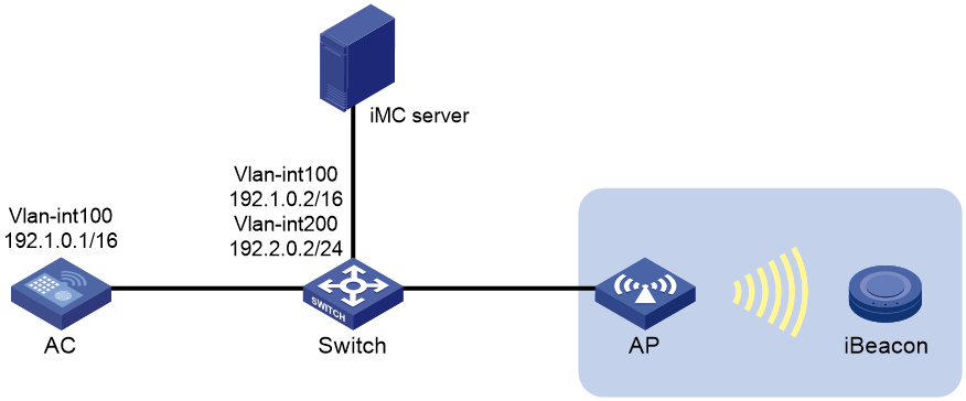
As shown in Figure 1, configure the AP to manage the iBeacon device. The AP collects BLE information and sends the information to the location server on the IMC server for calculation. Then, users can obtain information including electric quantity and RSSI of the iBeacon device. The AP also assigns management orders from the server to the iBeacon device.
Restrictions and guidelines
Use the serial ID labeled on the AP's rear panel to specify an AP.
Procedures
Configuring the AC
1. Configure interfaces on the AC:
# Create VLAN 100 and VLAN-interface 100, and assign an IP address to the VLAN interface. The AC will use this IP address to establish a CAPWAP tunnel with the AP.
<AC> system-view
[AC] vlan 100
[AC-vlan100] quit
[AC] interface vlan-interface 100
[AC-Vlan-interface100] ip address 192.1.0.1 16
[AC-Vlan-interface100] quit
# Create VLAN 200 and VLAN-interface 200, and configure the VLAN interface to use DHCP for IP address acquisition.
<AC> system-view
[AC] vlan 200
[AC-vlan200] quit
[AC] interface vlan-interface 200
[AC-Vlan-interface200] ip address dhcp-alloc
[AC-Vlan-interface200] quit
# Configure GigabitEthernet 1/0/1 that connects the AC and the switch as a trunk port, remove the port from VLAN 1, and assign it to VLANs 100 and 200.
[AC] interface gigabitethernet 1/0/1
[AC-GigabitEthernet1/0/1] port link-type trunk
[AC-GigabitEthernet1/0/1] undo port trunk permit vlan 1
[AC-GigabitEthernet1/0/1] port trunk permit vlan 100 200
[AC-GigabitEthernet1/0/1] quit
2. Create a manual AP named ap1, and specify the AP model and serial ID
[AC] wlan ap ap1 model WA4320-ACN-B
[AC-wlan-ap-ap1] serial-id 210236A35VA11A100678ACNB
3. Configure a module:
# Enter the view of module 1.
[AC-wlan-ap-ap1] module 1
# Specify the supported module type BLE for module 1, and enable module 1.
[AC-wlan-ap-ap1-module-1] type ble
[AC-wlan-ap-ap1-module-1] module enable
[AC-wlan-ap-ap1-module-1] quit
4. Configure BLE location:
# Enable BLE location.
[AC-wlan-ap-ap1] rfid-tracking ble enable
# Set the IPv4 address and port number of the location server to 192.2.0.1 and 1145, respectively. In this example, the IP address of the BLE location server is the IMC server's IP address obtained through DHCP.
[AC-wlan-ap-ap1] rfid-tracking ble engine-address 192.2.0.1 engine-port 1145
# Enable BLE neighbor list reporting for AP ap1.
[AC-wlan-ap-ap1] rfid-tracking ble report enable
# Configure the AP to send BLE neighbor list reports to the location server every 10 seconds.
[AC-wlan-ap-ap1] rfid-tracking ble report interval 10
# Specify the default password for deploying configuration to iBeacon devices as AprilBrother in plaintext form. Make sure the specified password is the same as the factory password of the iBeacon device.
[AC-wlan-ap-ap1] rfid-tracking ble command-password simple AprilBrother
[AC-wlan-ap-ap1] quit
Configuring the switch
1. Configure interfaces on the switch:
# Create VLAN 100 and VLAN-interface 100, and assign an IP address to the VLAN interface. The switch will use this VLAN to communicate with the AC.
<Switch> system-view
[Switch] vlan 100
[Switch-vlan100] quit
[Switch] interface vlan-interface 100
[Switch-Vlan-interface100] ip address 192.1.0.2 16
[Switch-Vlan-interface100] quit
# Create VLAN 200 and VLAN-interface 200, and assign an IP address to the VLAN interface. The switch will use this VLAN to forward traffic for the IMC server.
[Switch] vlan 200
[Switch-vlan200] quit
[Switch] interface vlan-interface 200
[Switch-Vlan-interface200] ip address 192.2.0.2 24
[Switch-Vlan-interface200] quit
# Configure GigabitEthernet 1/0/1 that connects the switch and the AC as a trunk port, remove the port from VLAN 1, and assign the trunk port to VLANs 100 and 200.
[Switch] interface gigabitethernet 1/0/1
[Switch-GigabitEthernet1/0/1] port link-type trunk
[Switch-GigabitEthernet1/0/1] undo port trunk permit vlan 1
[Switch-GigabitEthernet1/0/1] port trunk permit vlan 100 200
[Switch-GigabitEthernet1/0/1] quit
# Configure GigabitEthernet 1/0/2 that connects the switch and the IMC server as an access port, and assign the port to VLAN 200.
[Switch] interface gigabitethernet 1/0/2
[Switch-GigabitEthernet1/0/2] port link-type access
[Switch-GigabitEthernet1/0/2] port access vlan 200
[Switch-GigabitEthernet1/0/2] quit
# Configure GigabitEthernet 1/0/3 that connects the switch and AP as an access port, and assign the port to VLAN 100.
[Switch] interface gigabitethernet 1/0/3
[Switch-GigabitEthernet1/0/3] port link-type access
[Switch-GigabitEthernet1/0/3] port access vlan 100
# Enable PoE on GigabitEthernet 1/0/3.
[Switch-GigabitEthernet1/0/3] poe enable
[Switch-GigabitEthernet1/0/3] quit
2. Configure DHCP services:
# Enable DHCP.
[Switch] dhcp enable
# Create a DHCP address pool named 1 to assign an IP address to the AP.
[Switch] dhcp server ip-pool 1
# In DHCP address pool 1, specify subnet 192.1.0.0/16 for dynamic allocation, exclude IP address 192.1.0.1 from dynamic allocation, and specify gateway IP address 192.1.0.2.
[Switch] dhcp server ip-pool 1
[Switch-dhcp-pool-1] network 192.1.0.0 mask 255.255.0.0
[Switch-dhcp-pool-1] forbidden-ip 192.1.0.1
[Switch-dhcp-pool-1] gateway-list 192.1.0.2
[Switch-dhcp-pool-1] quit
# Create a DHCP address pool named 2, and specify subnet 192.2.0.0/24 and gateway address 192.2.0.2 for the AC's VLAN-interface 200 and the IMC server.
[Switch] dhcp server ip-pool 2
[Switch-dhcp-pool-2] network 192.2.0.0 mask 255.255.255.0
[Switch-dhcp-pool-2] gateway-list 192.2.0.2
[Switch-dhcp-pool-2] quit
Configuring the IMC server
In this example, the RADIUS server runs IMC PLAT 7.2(E0403L02) and IMC WSM 7.2(E0502L03).
To configure the IMC server:
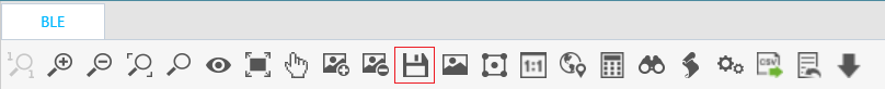
1. Add a location:
a. Click the Service tab.
b. From the navigation tree, select WLAN Manager > Location View.
c. Click Add.
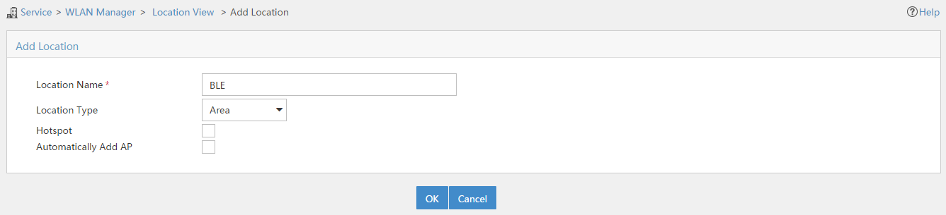
The Add Location page opens.
d. Configure the following parameters, as shown in Figure 2:
- Enter BLE in the Location Name field.
- Use the default settings for other parameters.
e. Click OK.
Figure 2 Adding a location
2. Add a Bluetooth AP:
a. On the newly created location view page, click Add, as shown in Figure 3.
The Select Devices page opens.
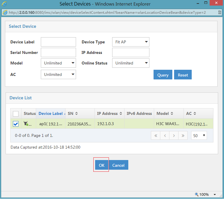
b. On the Device List area, select the target Bluetooth AP, as shown in Figure 4.
Figure 3 Adding a Bluetooth AP
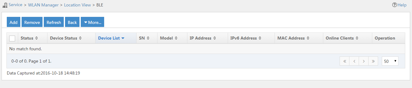
Figure 4 Selecting a Bluetooth AP
3. Add a topology:
a. On the newly created location view page, click the icon of viewing topology, as shown in Figure 5.
The topology configuration page opens.
b. Click the icon of adding a map, as shown in Figure 6.
c. Click the icon of setting the measuring scale, as shown in Figure 7.
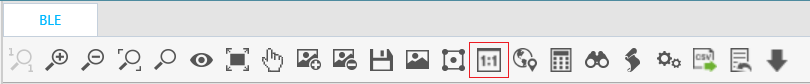
d. Click the save icon to save the topology, as shown in Figure 8.
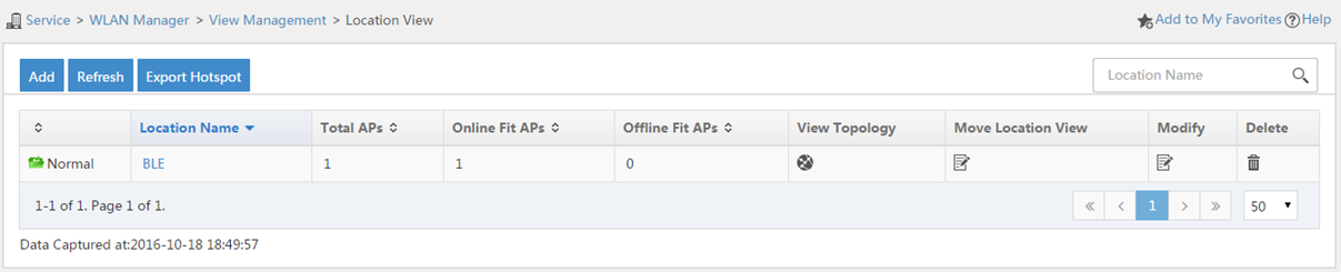
Figure 6 Adding a map
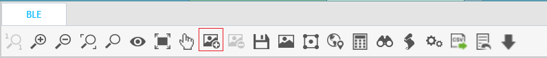
Figure 7 Adding a measuring scale
Verifying the configuration
1. Log in to the IMC management platform, and click the Service tab.
2. From the navigation tree, select WLAN Manager > Location Manager> iBeacon List.
3. On the page that opens, view the iBeacon information, including electric quantity, RSSI, UUID, Major ID, Minor ID, and transmit power.
Configuration files
· AC:
#
vlan 100
#
interface Vlan-interface100
ip address 192.1.0.1 255.255.0.0
#
interface Vlan-interface200
ip address dhcp-alloc
#
interface GigabitEthernet1/0/1
port link-type trunk
port trunk permit vlan 100 200
undo port trunk permit vlan 1
#
wlan ap ap1 model WA4320-ACN-B
serial-id 210236A35VA11A100678ACNB
rfid-tracking ble command-password cipher $c$3$AAu3rmjHUmAE0W12Rk1Jco6MPJ3Iqoh+pFgqhkFihw==
rfid-tracking ble enable
rfid-tracking ble engine-address 192.2.0.1 engine-port 1145
rfid-tracking ble report enable
rfid-tracking ble report interval 10
radio 1
radio 2
module 1
type BLE
module enable
#
· Switch:
#
dhcp enable
#
vlan 100
#
vlan 200
#
dhcp server ip-pool 1
gateway-list 192.1.0.2
network 192.1.0.0 mask 255.255.0.0
forbidden-ip 192.1.0.1
#
dhcp server ip-pool 2
gateway-list 192.2.0.2
network 192.2.0.0 mask 255.255.255.0
#
interface Vlan-interface100
ip address 192.1.0.2 255.255.0.0
#
interface Vlan-interface200
ip address 192.2.0.2 255.255.255.0
#
interface GigabitEthernet1/0/1
port link-type trunk
port trunk permit vlan 100 200
undo port trunk permit vlan 1
#
interface GigabitEthernet1/0/2
port access vlan 200
#
interface GigabitEthernet1/0/3
port access vlan 100
poe enable
#
Related documentation
· Internet of Things Command Reference in H3C Access Controllers Command References
· Internet of Things Configuration Guide in H3C Access Controllers Configuration Guides
· WLAN Advanced Features Command Reference in H3C Access Controllers Command References
· WLAN Advanced Features Configuration Guide in H3C Access Controllers Configuration Guides
