- Table of Contents
-
- 03-CLI configuration examples (AC+fit AP)
- 01-HTTPS Login Configuration Examples
- 02-SSH Configuration Examples
- 03-License Management Configuration Examples
- 04-IPv6 URL Redirection Configuration Examples
- 05-AP Association with the AC at Layer 2 Configuration Examples
- 06-AP Association with the AC at Layer 2 (IPv6) Configuration Examples
- 07-Auto AP Configuration Examples
- 08-AP Association with the AC at Layer 3 Configuration Examples
- 09-AP Association with the AC at Layer 3 (IPv6) Configuration Examples
- 10-WEP Encryption Configuration Examples
- 11-PSK Encryption Configuration Examples
- 12-WPA3-SAE PSK Encryption Configuration Examples
- 13-WLAN Access (IPv6) Configuration Examples
- 14-Policy-Based Forwarding with Dual Gateways Configuration Examples
- 15-Scheduled Configuration Deployment by AP Group Configuration Examples
- 16-Inter-AC Roaming with Static Client VLAN Allocation Configuration Examples
- 17-Service Template and Radio Binding Configuration Examples
- 18-Scheduled WLAN Access Services Configuration Examples
- 19-Local Portal Authentication Configuration Examples
- 20-HTTPS-Based Local Portal Authentication Configuration Examples
- 21-Remote Portal Authentication Configuration Examples
- 22-Local Portal Authentication through LDAP Server Configuration Examples
- 23-Local Portal Authentication and SSID-based Authentication Page Pushing Configuration Examples
- 24-Local Portal MAC-Trigger Authentication Configuration Examples
- 25-Portal MAC-Trigger Authentication Configuration Examples
- 26-Local Forwarding Mode and Local Portal MAC-Trigger Authentication Configuration Examples
- 27-Local Portal Authentication (IPv6) Configuration Examples
- 28-Local Portal Authentication through LDAP Server (IPv6) Configuration Examples
- 29-Remote Portal Authentication (IPv6) Configuration Examples
- 30-Portal MAC-Trigger Authentication (IPv6) Configuration Example
- 31-Remote Portal Authentication with User Profile Authorization Configuration Examples
- 32-Portal Fail-Permit Configuration Examples
- 33-Local MAC Authentication Configuration Examples
- 34-MAC Authentication and PSK Authentication Configuration Examples
- 35-Remote MAC and Portal Authentication and Transparent Authentication Configuration Examples
- 36-Remote AP and Remote Portal MAC-Trigger Authentication Configuration Examples
- 37-MAC Authentication with Guest VLAN Assignment Configuration Examples
- 38-MAC Authentication with Guest VLAN Assignment (IPv6) Configuration Examples
- 39-Local MAC-Then-802.1X Authentication Configuration Examples
- 40-Local 802.1X Authentication Configuration Examples
- 41-Local RADIUS-Based 802.1X Authentication in EAP Relay Mode Configuration Examples
- 42-Remote 802.1X Authentication Configuration Examples
- 43-Remote 802.1X Authentication (IPv6) Configuration Examples
- 44-Remote 802.1X Authentication in WPA3-Enterprise Mode Configuration Examples
- 45-802.1X Authentication with ACL Assignment Through IMC Server Configuration Examples
- 46-802.1X Authentication with User Profile Assignment Through IMC Server Configuration Examples
- 47-EAD Authentication Configuration Examples
- 48-EAD Authentication (IPv6) Configuration Examples
- 49-Local Forwarding Mode and Local Portal Authentication Configuration Examples
- 50-Local Forwarding Mode Direct Portal Authentication Configuration Examples
- 51-Local Forwarding Mode Direct Portal Authentication (IPv6) Configuration Examples
- 52-Local Forwarding Configuration Examples
- 53-Remote AP Configuration Examples
- 54-WIPS Configuration Examples
- 55-WIPS Countermeasures Against All SSIDs Configuration Examples
- 56-IP Source Guard (IPv4) Configuration Examples
- 57-IP Source Guard (IPv6) Configuration Examples
- 58-IRF Setup with Members Directly Connected Configuration Examples
- 59-IRF Setup with Members Not Directly Connected Configuration Examples
- 60-IRF Setup with Members in One Chassis Configuration Examples
- 61-IRF Setup with Members in Different Chassis Configuration Examples
- 62-Dual-Link Backup Configuration Examples
- 63-Remote 802.1X Auth on AC Hierarchy Network with Dual-Link Central AC Backup Configuration Examples
- 64-Remote Portal Auth on AC Hierarchy Network with Dual-Link Central AC Backup Configuration Examples
- 65-OAuth-Based Portal MAC-Trigger Auth on Local-Forwarding Dual-Link Backup Configuration Examples
- 66-Dual-Link Backup OAuth-Based Portal Auth in Local Forwarding Configuration Examples
- 67-Dual-Link Backup Remote Portal MAC-Trigger Auth in Local Forwarding Configuration Examples
- 68-Dual-Link Backup Remote Portal and Transparent MAC Auth in Local Forwarding Configuration Examples
- 69-Dual-Link Backup Remote Portal Auth in Local Forwarding Configuration Examples
- 70-Dual-Link Backup Remote Portal and MAC Auth in Centralized Forward Configuration Examples
- 71-Dual-Link Backup Remote Portal Auth in Centralized Forwarding Configuration Examples
- 72-Dual-Link Backup Lightweight Portal Auth in Centralized Forwarding Configuration Examples
- 73-Dual-Link Backup OAuth-Based Portal Auth in Centralized Forwarding Configuration Examples
- 74-Dual-Link Backup Remote Portal MAC-Trigger Auth in Centralized Forwarding Configuration Examples
- 75-Remote 802.1X Auth on a Dual-Link AC Backup Network Configuration Examples
- 76-Remote MAC Auth on a Dual-Link AC Backup Network Configuration Examples
- 77-Remote 802.1X Authentication on an AC Hierarchy Network Configuration Examples
- 78-Remote 802.1X Authentication Configuration Examples
- 79-WLAN Probe Configuration Examples
- 80-Multicast Optimization Configuration Examples
- 81-Client Rate Limiting Configuration Examples
- 82-Inter-AC Roaming Configuration Examples
- 83-Inter-AC Roaming (IPv6) Configuration Examples
- 84-WLAN Load Balancing Configuration Examples
- 85-Static Blacklist Configuration Examples
- 86-Client Quantity Control Configuration Examples
- 87-AP License Synchronization Configuration Examples
- 88-iBeacon Management Configuration Examples
- 89-Mesh Link Establishment Between a Fit AP and a Fat AP Configuration Examples
- 90-Mesh Link Establishment Between Fit APs Configuration Examples
- 91-Auto-DFS and Auto-TPC Configuration Examples
- 92-AP Image Downloading Configuration Examples
- 93-Dual-Uplink Interfaces Configuration Guide
- 94-Internal-to-External Access Through NAT Configuration Examples
- 95-Layer 2 Static Aggregation Configuration Examples
- 96-Layer 2 Multicast Configuration Examples
- 97-Static VLAN Allocation Configuration Examples
- 98-URL Redirection Configuration Examples
- Related Documents
-
| Title | Size | Download |
|---|---|---|
| 58-IRF Setup with Members Directly Connected Configuration Examples | 93.64 KB |
|
|
|
H3C Access Controllers |
|
Comware 7 IRF Setup with Members Directly Connected |
|
Configuration Examples |
Copyright © 2022 New H3C Technologies Co., Ltd. All rights reserved.
No part of this manual may be reproduced or transmitted in any form or by any means without prior written consent of New H3C Technologies Co., Ltd.
Except for the trademarks of New H3C Technologies Co., Ltd., any trademarks that may be mentioned in this document are the property of their respective owners.
The information in this document is subject to change without notice.
Contents
Example: Setting up a two-member IRF fabric with members directly connected
IRF topo-domain ID and MAD domain ID restrictions
IRF network interface shutdown restrictions
IRF member device bridge MAC address restrictions
IRF port binding removal restrictions
Feature compatibility and configuration restrictions
Introduction
The following information provides an example for setting up an IRF fabric with two member devices that are directly connected.
The Intelligent Resilient Framework (IRF) technology is proprietary to H3C. This technology is a true stacking technology that creates a large virtual stack called IRF fabric from multiple devices to provide data center class availability and scalability. IRF offers processing power, interaction, unified management, and uninterrupted maintenance of multiple devices.
Prerequisites
The following information applies to Comware 7-based access controllers and access points. Procedures and information in the examples might be slightly different depending on the software or hardware version of the access controllers and access points.
The configuration examples were created and verified in a lab environment, and all the devices were started with the factory default configuration. When you are working on a live network, make sure you understand the potential impact of every command on your network.
The following information is provided based on the assumption that you have basic knowledge of IRF and Ethernet link aggregation.
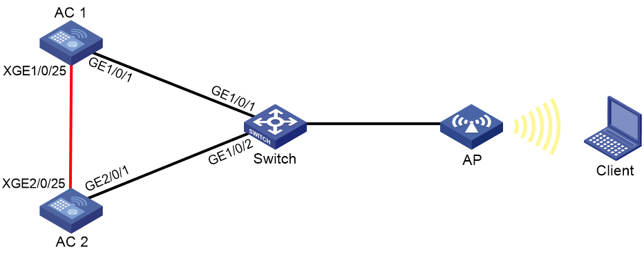
Example: Setting up a two-member IRF fabric with members directly connected
Network configuration
As shown in Figure 1, use AC 1 and AC 2 to set up an IRF fabric. The IRF network interfaces on the ACs are directly connected.
Configure LACP MAD on the multi-member link aggregation to the switch, an H3C device that supports extended LACP.
Restrictions and guidelines
When you set up an IRF fabric with members directly connected, follow the restrictions and guidelines in this section.
Hardware compatibility
An access controller can form an IRF fabric only with access controllers of the same model.
Software requirements
All IRF member devices must run the same software image version as the master. For software synchronization, make sure the software auto-update feature is enabled.
IRF size restrictions
The maximum number of member devices in an IRF fabric varies by device model.
IRF member ID restrictions
Make sure each IRF member device is assigned a unique member ID. For a new member ID to take effect, you must reboot the device.
The port number of the IRF port is the same as the IRF member ID of the device.
IRF topo-domain ID and MAD domain ID restrictions
Make sure all member devices have the same topo-domain ID and MAD domain ID. For a new topo-domain ID to take effect on a device, you must reboot the device.
IRF port binding requirements
An IRF port must have a minimum of one hybrid channel, or a minimum of one data channel and one control channel.
The network interfaces bound to an IRF port must operate at the same rate. The two ends of an IRF link must operate at the same rate.
For the port bindings to take effect, perform the following tasks:
1. Save the configuration.
2. Reboot the device or activate the IRF port configuration.
IRF network interface shutdown restrictions
You cannot use the shutdown command on the IRF standby device to shut down an IRF network interface if the interface is the only control channel available on the device. To shut down the IRF link in this situation, shut down the IRF network interface on the master device.
Connectivity requirements
Make sure the member devices have Layer 2 connectivity with each other.
If the IRF fabric contains only two member devices, you can connect the member devices directly or through Layer 2 intermediate devices. If the IRF fabric contains more than two member devices, you must connect the member devices through Layer 2 intermediate devices.
IRF merge restrictions
If the IRF fabric splits, do not change the IRF settings on any IRF member devices before they reunite.
IRF member device bridge MAC address restrictions
Member devices cannot join the same IRF fabric if they have the same bridge MAC address.
IRF port binding removal restrictions
To remove a network interface from an IRF port, you must first shut down the IRF network interface.
Feature compatibility and configuration restrictions
Ethernet link aggregation restrictions
On the Layer 2 intermediate devices, do not configure per-packet load sharing on the Layer 2 link aggregation groups that connect to multiple member devices of the IRF fabric.
As a best practice, configure Ethernet link aggregation settings after the IRF fabric is formed.
VLAN restrictions
Do not assign IRF links to VLANs that run on links that forward data traffic.
NAT restrictions
NAT is not supported on an IRF fabric.
Procedures
Configuring the switch
# Create Layer 2 aggregate interface Bridge-Aggregation 1, and configure the aggregation group of the aggregate interface to operate in dynamic mode.
<Switch> system-view
[Switch] interface bridge-aggregation 1
[Switch-Bridge-Aggregation1] link-aggregation mode dynamic
[Switch-Bridge-Aggregation1] quit
# Assign GigabitEthernet 1/0/1 to aggregation group 1.
[Switch] interface gigabitethernet 1/0/1
[Switch-GigabitEthernet1/0/1] port link-aggregation group 1
[Switch-GigabitEthernet1/0/1] quit
# Assign GigabitEthernet 1/0/2 to aggregation group 1.
[Switch] interface gigabitethernet 1/0/2
[Switch-GigabitEthernet1/0/2] port link-aggregation group 1
[Switch-GigabitEthernet1/0/2] quit
# Enable link-aggregation traffic redirection.
[Switch] link-aggregation lacp traffic-redirect-notification enable
Configuring AC 1
# Assign Ten-GigabitEthernet 1/0/25 to IRF-port 1.
<AC1> system-view
[AC1] irf-port 1
[AC1-irf-port1] port group interface ten-gigabitethernet 1/0/25
[AC1-irf-port1] quit
# Specify the member priority as 2. AC 1 will be the master device.
[AC1] irf member 1 priority 2
# Save the configuration.
[AC1] save
The current configuration will be written to the device. Are you sure? [Y/N]:y
Please input the file name(*.cfg)[cfa0:/startup.cfg]
(To leave the existing filename unchanged, press the enter key):
Validating file. Please wait...
Saved the current configuration to mainboard device successfully.
# Activate the IRF port configuration.
[AC1] irf-port-configuration active
Configuring AC 2
# Change the IRF member ID to 2.
<AC2> system-view
[AC2] irf member 1 renumber 2
Renumbering the member ID may result in configuration change or loss. Continue?[
Y/N]:y
[AC2] quit
# Reboot the AC for the new member ID to take effect.
<AC2> reboot
Start to check configuration with next startup configuration file, please wait..
.......DONE!
Current configuration may be lost after the reboot, save current configuration?
[Y/N]:y
Please input the file name(*.cfg)[cfa0:/startup.cfg]
(To leave the existing filename unchanged, press the enter key):
cfa0:/startup.cfg exists, overwrite? [Y/N]:y
Validating file. Please wait...
Saved the current configuration to mainboard device successfully.
This command will reboot the device. Continue? [Y/N]:y
Now rebooting, please wait...
# Assign Ten-GigabitEthernet 2/0/25 to the IRF port.
<AC2> system-view
[AC2] irf-port 2
[AC2-irf-port2] port group interface ten-gigabitethernet 2/0/25
[AC2-irf-port2] quit
# Save the configuration.
[AC2] save
The current configuration will be written to the device. Are you sure? [Y/N]:y
Please input the file name(*.cfg)[cfa0:/startup.cfg]
(To leave the existing filename unchanged, press the enter key):
Validating file. Please wait...
Saved the current configuration to mainboard device successfully.
# Activate the IRF port configuration.
[AC2] irf-port-configuration active
System is starting...
AC 1 and AC 2 perform master election. AC 2 fails master election and reboots to form an IRF fabric with AC 1.
Configuring the IRF fabric
# Change the name of the IRF fabric to IRF.
<AC1> system-view
[AC1] system-name IRF
# Configure descriptions for AC 1 and AC 2, respectively.
[IRF] irf member 1 description AC 1
[IRF] irf member 2 description AC 2
# Create a Layer 2 aggregate interface named Bridge-Aggregation 1, and configure the aggregation group of the aggregate interface to operate in dynamic mode.
[IRF] interface bridge-aggregation 1
[IRF-Bridge-Aggregation1] link-aggregation mode dynamic
# Enable LACP MAD on the aggregate interface.
[IRF-Bridge-Aggregation1] mad enable
[IRF-Bridge-Aggregation1] quit
# Enable link-aggregation traffic redirection.
[IRF] link-aggregation lacp traffic-redirect-notification enable
# Assign GigabitEthernet 1/0/1 to aggregation group 1.
[IRF] interface gigabitethernet 1/0/1
[IRF-GigabitEthernet1/0/1] port link-aggregation group 1
[IRF-GigabitEthernet1/0/1] quit
# Assign GigabitEthernet 2/0/1 to aggregation group 1.
[IRF] interface gigabitethernet 2/0/1
[IRF-GigabitEthernet2/0/1] port link-aggregation group 1
[IRF-GigabitEthernet2/0/1] quit
Verifying the configuration
# Display IRF information. Verify that AC 1 is the master device.
[IRF] display irf
Member ID Role Priority CPU MAC Description
*1 Master 2 50da-0051-2608 AC 1
+2 Standby 1 50da-0051-2670 AC 2
--------------------------------------------------
The asterisk (*) indicates the master.
The plus sign (+) indicates the device through which you are logged in.
The right angle bracket (>) indicates the device's stack capability is disabled.
Bridge MAC of the IRF: 50da-0051-2608
Auto upgrade : Enabled
MAC persistence : 6 min
Topo-domain ID : 0
Auto merge : Enabled
# Display IRF link information. Verify that the IRF network interfaces on both member devices are up.
[IRF] display irf link
Member ID Member Interfaces Status
1 XGE1/0/25(ctrl&data) Up
2 XGE2/0/25(ctrl&data) Up
# On the IRF fabric, display detailed information about aggregation groups. Verify that GigabitEthernet 1/0/1 and GigabitEthernet 2/0/1 are in aggregation group 1 and in Selected state.
[IRF] display link-aggregation verbose
Loadsharing Type: Shar -- Loadsharing, NonS -- Non-Loadsharing
Port Status: S -- Selected, U -- Unselected, I -- Individual
Flags: A -- LACP_Activity, B -- LACP_Timeout, C -- Aggregation,
D -- Synchronization, E -- Collecting, F -- Distributing,
G -- Defaulted, H -- Expired
Aggregate Interface: Bridge-Aggregation1
Aggregation Mode: Dynamic
Loadsharing Type: Shar
System ID: 0x8000, 50da-0051-2608
Local:
Port Status Priority Oper-Key Flag
--------------------------------------------------------------------------------
GE1/0/1 S 32768 1 {ACDEF}
GE2/0/1 S 32768 1 {ACDEF}
Remote:
Actor Partner Priority Oper-Key SystemID Flag
--------------------------------------------------------------------------------
GE1/0/1 1 32768 1 0x8000, 3897-d633-f3c6 {ACDEF}
GE2/0/1 2 32768 1 0x8000, 3897-d633-f3c6 {ACDEF}
# On the switch, display detailed information about aggregation groups. Verify that GigabitEthernet 1/0/1 and GigabitEthernet 1/0/2 are in aggregation group 1 and in Selected state.
[Switch] display link-aggregation verbose
Loadsharing Type: Shar -- Loadsharing, NonS -- Non-Loadsharing
Port Status: S -- Selected, U -- Unselected,
I -- Individual, * -- Management port
Flags: A -- LACP_Activity, B -- LACP_Timeout, C -- Aggregation,
D -- Synchronization, E -- Collecting, F -- Distributing,
G -- Defaulted, H -- Expired
Aggregate Interface: Bridge-Aggregation1
Aggregation Mode: Dynamic
Loadsharing Type: Shar
Management VLAN : None
System ID: 0x8000, 3897-d633-f3c6
Local:
Port Status Priority Oper-Key Flag
--------------------------------------------------------------------------------
GE1/0/1 S 32768 1 {ACDEF}
GE1/0/2 S 32768 1 {ACDEF}
Remote:
Actor Partner Priority Oper-Key SystemID Flag
--------------------------------------------------------------------------------
GE1/0/1 2 32768 1 0x8000, 50da-0051-2608 {ACDEF}
GE1/0/2 31 32768 1 0x8000, 50da-0051-2608 {ACDEF}
Configuration files
· IRF fabric:
#
sysname IRF
#
irf mac-address persistent timer
irf auto-update enable
irf auto-merge enable
irf member 1 priority 2
irf member 2 priority 1
irf member 1 description AC 1
irf member 2 description AC 2
#
link-aggregation lacp traffic-redirect-notification enable
#
irf-port 1
port group interface Ten-GigabitEthernet1/0/25
#
irf-port 2
port group interface Ten-GigabitEthernet2/0/25
#
interface Bridge-Aggregation1
link-aggregation mode dynamic
mad enable
#
interface GigabitEthernet1/0/1
port link-aggregation group 1
#
interface GigabitEthernet2/0/1
port link-aggregation group 1
#
· Switch:
#
link-aggregation lacp traffic-redirect-notification enable
#
interface Bridge-Aggregation1
link-aggregation mode dynamic
#
interface GigabitEthernet1/0/1
port link-aggregation group 1
#
interface GigabitEthernet1/0/2
port link-aggregation group 1
#
Related documentation
· High Availability Configuration Guide in H3C Access Controllers Configuration Guides
· High Availability Command Reference in H3C Access Controllers Command References
· Network Connectivity Configuration Guide in H3C Access Controllers Configuration Guides
· Network Connectivity Command Reference in H3C Access Controllers Command References
