- Table of Contents
-
- 03-CLI configuration examples (AC+fit AP)
- 01-HTTPS Login Configuration Examples
- 02-SSH Configuration Examples
- 03-License Management Configuration Examples
- 04-IPv6 URL Redirection Configuration Examples
- 05-AP Association with the AC at Layer 2 Configuration Examples
- 06-AP Association with the AC at Layer 2 (IPv6) Configuration Examples
- 07-Auto AP Configuration Examples
- 08-AP Association with the AC at Layer 3 Configuration Examples
- 09-AP Association with the AC at Layer 3 (IPv6) Configuration Examples
- 10-WEP Encryption Configuration Examples
- 11-PSK Encryption Configuration Examples
- 12-WPA3-SAE PSK Encryption Configuration Examples
- 13-WLAN Access (IPv6) Configuration Examples
- 14-Policy-Based Forwarding with Dual Gateways Configuration Examples
- 15-Scheduled Configuration Deployment by AP Group Configuration Examples
- 16-Inter-AC Roaming with Static Client VLAN Allocation Configuration Examples
- 17-Service Template and Radio Binding Configuration Examples
- 18-Scheduled WLAN Access Services Configuration Examples
- 19-Local Portal Authentication Configuration Examples
- 20-HTTPS-Based Local Portal Authentication Configuration Examples
- 21-Remote Portal Authentication Configuration Examples
- 22-Local Portal Authentication through LDAP Server Configuration Examples
- 23-Local Portal Authentication and SSID-based Authentication Page Pushing Configuration Examples
- 24-Local Portal MAC-Trigger Authentication Configuration Examples
- 25-Portal MAC-Trigger Authentication Configuration Examples
- 26-Local Forwarding Mode and Local Portal MAC-Trigger Authentication Configuration Examples
- 27-Local Portal Authentication (IPv6) Configuration Examples
- 28-Local Portal Authentication through LDAP Server (IPv6) Configuration Examples
- 29-Remote Portal Authentication (IPv6) Configuration Examples
- 30-Portal MAC-Trigger Authentication (IPv6) Configuration Example
- 31-Remote Portal Authentication with User Profile Authorization Configuration Examples
- 32-Portal Fail-Permit Configuration Examples
- 33-Local MAC Authentication Configuration Examples
- 34-MAC Authentication and PSK Authentication Configuration Examples
- 35-Remote MAC and Portal Authentication and Transparent Authentication Configuration Examples
- 36-Remote AP and Remote Portal MAC-Trigger Authentication Configuration Examples
- 37-MAC Authentication with Guest VLAN Assignment Configuration Examples
- 38-MAC Authentication with Guest VLAN Assignment (IPv6) Configuration Examples
- 39-Local MAC-Then-802.1X Authentication Configuration Examples
- 40-Local 802.1X Authentication Configuration Examples
- 41-Local RADIUS-Based 802.1X Authentication in EAP Relay Mode Configuration Examples
- 42-Remote 802.1X Authentication Configuration Examples
- 43-Remote 802.1X Authentication (IPv6) Configuration Examples
- 44-Remote 802.1X Authentication in WPA3-Enterprise Mode Configuration Examples
- 45-802.1X Authentication with ACL Assignment Through IMC Server Configuration Examples
- 46-802.1X Authentication with User Profile Assignment Through IMC Server Configuration Examples
- 47-EAD Authentication Configuration Examples
- 48-EAD Authentication (IPv6) Configuration Examples
- 49-Local Forwarding Mode and Local Portal Authentication Configuration Examples
- 50-Local Forwarding Mode Direct Portal Authentication Configuration Examples
- 51-Local Forwarding Mode Direct Portal Authentication (IPv6) Configuration Examples
- 52-Local Forwarding Configuration Examples
- 53-Remote AP Configuration Examples
- 54-WIPS Configuration Examples
- 55-WIPS Countermeasures Against All SSIDs Configuration Examples
- 56-IP Source Guard (IPv4) Configuration Examples
- 57-IP Source Guard (IPv6) Configuration Examples
- 58-IRF Setup with Members Directly Connected Configuration Examples
- 59-IRF Setup with Members Not Directly Connected Configuration Examples
- 60-IRF Setup with Members in One Chassis Configuration Examples
- 61-IRF Setup with Members in Different Chassis Configuration Examples
- 62-Dual-Link Backup Configuration Examples
- 63-Remote 802.1X Auth on AC Hierarchy Network with Dual-Link Central AC Backup Configuration Examples
- 64-Remote Portal Auth on AC Hierarchy Network with Dual-Link Central AC Backup Configuration Examples
- 65-OAuth-Based Portal MAC-Trigger Auth on Local-Forwarding Dual-Link Backup Configuration Examples
- 66-Dual-Link Backup OAuth-Based Portal Auth in Local Forwarding Configuration Examples
- 67-Dual-Link Backup Remote Portal MAC-Trigger Auth in Local Forwarding Configuration Examples
- 68-Dual-Link Backup Remote Portal and Transparent MAC Auth in Local Forwarding Configuration Examples
- 69-Dual-Link Backup Remote Portal Auth in Local Forwarding Configuration Examples
- 70-Dual-Link Backup Remote Portal and MAC Auth in Centralized Forward Configuration Examples
- 71-Dual-Link Backup Remote Portal Auth in Centralized Forwarding Configuration Examples
- 72-Dual-Link Backup Lightweight Portal Auth in Centralized Forwarding Configuration Examples
- 73-Dual-Link Backup OAuth-Based Portal Auth in Centralized Forwarding Configuration Examples
- 74-Dual-Link Backup Remote Portal MAC-Trigger Auth in Centralized Forwarding Configuration Examples
- 75-Remote 802.1X Auth on a Dual-Link AC Backup Network Configuration Examples
- 76-Remote MAC Auth on a Dual-Link AC Backup Network Configuration Examples
- 77-Remote 802.1X Authentication on an AC Hierarchy Network Configuration Examples
- 78-Remote 802.1X Authentication Configuration Examples
- 79-WLAN Probe Configuration Examples
- 80-Multicast Optimization Configuration Examples
- 81-Client Rate Limiting Configuration Examples
- 82-Inter-AC Roaming Configuration Examples
- 83-Inter-AC Roaming (IPv6) Configuration Examples
- 84-WLAN Load Balancing Configuration Examples
- 85-Static Blacklist Configuration Examples
- 86-Client Quantity Control Configuration Examples
- 87-AP License Synchronization Configuration Examples
- 88-iBeacon Management Configuration Examples
- 89-Mesh Link Establishment Between a Fit AP and a Fat AP Configuration Examples
- 90-Mesh Link Establishment Between Fit APs Configuration Examples
- 91-Auto-DFS and Auto-TPC Configuration Examples
- 92-AP Image Downloading Configuration Examples
- 93-Dual-Uplink Interfaces Configuration Guide
- 94-Internal-to-External Access Through NAT Configuration Examples
- 95-Layer 2 Static Aggregation Configuration Examples
- 96-Layer 2 Multicast Configuration Examples
- 97-Static VLAN Allocation Configuration Examples
- 98-URL Redirection Configuration Examples
- Related Documents
-
| Title | Size | Download |
|---|---|---|
| 52-Local Forwarding Configuration Examples | 352.95 KB |
|
H3C Access Controllers |
|
Comware 7 Local Forwarding |
|
Configuration Examples |
Copyright © 2022 New H3C Technologies Co., Ltd. All rights reserved.
No part of this manual may be reproduced or transmitted in any form or by any means without prior written consent of New H3C Technologies Co., Ltd.
Except for the trademarks of New H3C Technologies Co., Ltd., any trademarks that may be mentioned in this document are the property of their respective owners.
The information in this document is subject to change without notice.
Introduction
The following information provides an example for configuring WLAN local forwarding.
Prerequisites
This document applies to Comware 7-based access controllers and access points. Procedures and information in the examples might be slightly different depending on the software or hardware version of the access controllers and access points.
The configuration examples in this document were created and verified in a lab environment, and all the devices were started with the factory default configuration. When you are working on a live network, make sure you understand the potential impact of every command on your network.
This document assumes that you have basic knowledge of WLAN local forwarding.
Example: Configuring local forwarding
Network configuration
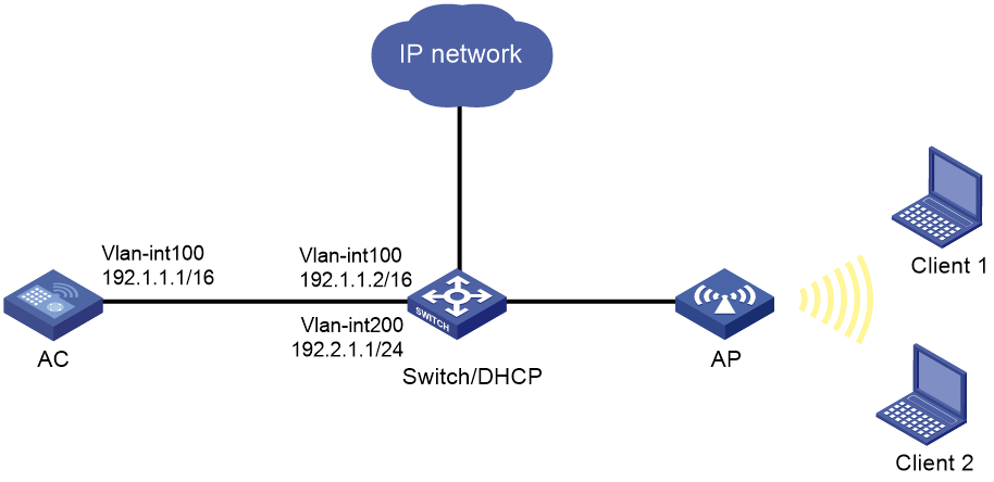
As shown in Figure 1, the switch acts as a DHCP server to assign IP addresses to the AP and the clients. The AP establishes CAPWAP tunnels with the AC in VLAN 100 and clients use VLAN 200 to access the WLAN. Configure local forwarding on the AC to enable the AP to forward client traffic.
Restrictions and guidelines
When you configure WLAN local forwarding, follow these restrictions and guidelines:
· Make sure there is no Tab or space at the end of the map-configuration command.
· Use the serial ID labeled on the AP's rear panel to specify an AP.
· If a backup AC is available, make sure the map-configuration file has been upgraded to the backup AC.
Procedures
Configuring the configuration file
# Create a .txt file named apcfg.txt and enter the following content:
system-view
vlan 200
quit
interface GigabitEthernet 1/0/1
port link-type trunk
port trunk permit vlan 200
# Upload the file to the AC.
Configuring the AC
1. Configure AC interfaces:
# Create VLAN 100 and VLAN-interface 100, and assign an IP address to the VLAN interface. The AC will use this IP address to establish a CAPWAP tunnel with the AP.
[AC] vlan 100
[AC-vlan100] quit
[AC] interface vlan-interface 100
[AC-Vlan-interface100] ip address 192.1.1.1 16
[AC-Vlan-interface100] quit
# Configure GigabitEthernet1/0/1 that connects the AC to the switch as a trunk port, and assign the port to VLAN 100.
[AC] interface gigabitethernet 1/0/1
[AC-GigabitEthernet1/0/1] port link-type trunk
[AC-GigabitEthernet1/0/1] port trunk permit vlan 100
[AC-GigabitEthernet1/0/1] quit
2. Configure wireless services:
# Create service template 1 and enter its view.
[AC] wlan service-template 1
# Configure the SSID as service.
[AC-wlan-st-1] ssid service
# Enable local forwarding for traffic in VLAN 200.
[AC-wlan-st-1] client forwarding-location ap vlan 200
# Enable the service template.
[AC-wlan-st-1] service-template enable
[AC-wlan-st-1] quit
3. Configure the AP:
# Create manual AP officeap, and specify the AP model and serial ID.
[AC] wlan ap officeap model WA4320i-ACN
[AC-wlan-ap-officeap] serial-id 219801A0T78159E09083
# Bind service template 1 and VLAN 200 to radio 2.
[AC-wlan-ap-officeap] radio 2
[AC-wlan-ap-officeap-radio-2] service-template 1 vlan 200
# Enable radio 2.
[AC-wlan-ap-officeap-radio-2] radio enable
[AC-wlan-ap-officeap-radio-2] quit
4. Deploy configuration file apcfg.txt to AP officeap.
[AC-wlan-ap-officeap] map-configuration apcfg.txt
[AC-wlan-ap-officeap] quit
Configuring the switch
1. Configure switch interfaces:
# Create VLAN 100 and VLAN-interface 100, and assign an IP address to the VLAN interface. The switch will use VLAN 100 to forward packets between the AC and the AP.
<Switch> system-view
[Switch] vlan 100
[Switch-vlan100] quit
[Switch] interface vlan-interface 100
[Switch-Vlan-interface100] ip address 192.1.1.2 16
[Switch-Vlan-interface100] quit
# Create VLAN 200 and VLAN-interface 200, and assign an IP address to the VLAN interface. The switch will use VLAN 200 to forward client traffic.
[Switch] vlan 200
[Switch-vlan200] quit
[Switch] interface vlan-interface 200
[Switch-Vlan-interface200] ip address 192.2.1.1 24
[Switch-Vlan-interface200] quit
# Configure GigabitEthernet 1/0/1 that connects the switch to the AC as a trunk port, and assign the port to VLAN 100.
[Switch] interface GigabitEthernet 1/0/1
[Switch-GigabitEthernet1/0/1] port link-type trunk
[Switch-GigabitEthernet1/0/1] port trunk permit vlan 100
[Switch-GigabitEthernet1/0/1] quit
# Configure GigabitEthernet 1/0/2 that connects the switch to the AP as a trunk port, remove the port from VLAN 1, set the PVID to VLAN 100, and assign the port to VLANs 100 and 200.
[Switch] interface GigabitEthernet 1/0/2
[Switch-GigabitEthernet1/0/2] port link-type trunk
[Switch-GigabitEthernet1/0/2] undo port trunk permit vlan 1
[Switch-GigabitEthernet1/0/2] port trunk permit vlan 100 200
[Switch-GigabitEthernet1/0/2] port trunk pvid vlan 100
# Enable PoE on GigabitEthernet 1/0/2.
[Switch-GigabitEthernet1/0/2] poe enable
[Switch-GigabitEthernet1/0/2] quit
2. Configure DHCP:
# Enable DHCP.
[Switch] dhcp enable
# Create DHCP address pool vlan100 to assign an IP address to the AP, and specify subnet 192.1.0.0/16 in the DHCP address pool.
[Switch] dhcp server ip-pool vlan100
[Switch-dhcp-pool-vlan100] network 192.1.0.0 mask 255.255.0.0
# Exclude IP address 192.1.1.1 from dynamic allocation in the address pool.
[Switch-dhcp-pool-vlan100] forbidden-ip 192.1.1.1
# Specify the gateway address as 192.1.1.2 in the DHCP address pool.
[Switch-dhcp-pool-vlan100] gateway-list 192.1.1.2
[Switch-dhcp-pool-vlan100] quit
# Create DHCP address pool vlan200 to assign IP addresses to clients, and specify subnet 192.2.1.0/24 in the DHCP address pool.
[Switch] dhcp server ip-pool vlan200
[Switch-dhcp-pool-vlan200] network 192.2.1.0 mask 255.255.255.0
# Specify the gateway address as 192.2.1.1 and specify the DNS server address in the DHCP address pool. In this example, the gateway also acts as a DNS server.
[Switch-dhcp-pool-vlan200] gateway-list 192.2.1.1
[Switch-dhcp-pool-vlan200] dns-list 192.2.1.1
[Switch-dhcp-pool-vlan200] quit
Verifying the configuration
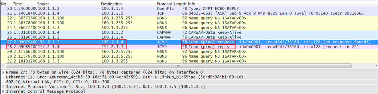
# Ping Client 1 on Client 2 and ping Client 2 on Client 1.
# Capture packets and verify that client traffic is forwarded by the AP.
Figure 2 ICMP packets from clients
Configuration files
· AC:
#
Vlan 100
#
wlan service-template 1
ssid service
client forwarding-location ap vlan 200
service-template enable
#
interface Vlan-interface100
ip address 192.1.1.1 255.255.0.0
#
interface GigabitEthernet1/0/1
port link-type trunk
port trunk permit vlan 1 100
#
wlan ap officeap model WA4320i-ACN
map-configuration flash:/apcfg.txt
serial-id 219801A0T78159E09083
radio 1
radio 2
radio enable
service-template 1 vlan 200
#
· Switch:
#
dhcp enable
#
vlan 100
#
vlan 200
#
dhcp server ip-pool vlan100
gateway-list 192.1.1.2
network 192.1.0.0 mask 255.255.0.0
forbidden-ip 192.1.1.1
#
dhcp server ip-pool vlan200
gateway-list 192.2.1.1
network 192.2.1.0 mask 255.255.255.0
dns-list 192.2.1.1
#
interface Vlan-interface100
ip address 192.1.1.2 255.255.0.0
#
interface Vlan-interface200
ip address 192.2.1.1 255.255.255.0
#
interface GigabitEthernet1/0/1
port link-mode bridge
port link-type trunk
port trunk permit vlan 1 100
#
interface GigabitEthernet1/0/2
port link-mode bridge
port link-type trunk
undo port trunk permit vlan 1
port trunk permit vlan 100 200
port trunk pvid vlan 100
#
Related documentation
· WLAN Access Command Reference in H3C Access Controllers Command References
· WLAN Access Configuration Guide in H3C Access Controllers Configuration Guides
