- Table of Contents
-
- 03-CLI configuration examples (AC+fit AP)
- 01-HTTPS Login Configuration Examples
- 02-SSH Configuration Examples
- 03-License Management Configuration Examples
- 04-IPv6 URL Redirection Configuration Examples
- 05-AP Association with the AC at Layer 2 Configuration Examples
- 06-AP Association with the AC at Layer 2 (IPv6) Configuration Examples
- 07-Auto AP Configuration Examples
- 08-AP Association with the AC at Layer 3 Configuration Examples
- 09-AP Association with the AC at Layer 3 (IPv6) Configuration Examples
- 10-WEP Encryption Configuration Examples
- 11-PSK Encryption Configuration Examples
- 12-WPA3-SAE PSK Encryption Configuration Examples
- 13-WLAN Access (IPv6) Configuration Examples
- 14-Policy-Based Forwarding with Dual Gateways Configuration Examples
- 15-Scheduled Configuration Deployment by AP Group Configuration Examples
- 16-Inter-AC Roaming with Static Client VLAN Allocation Configuration Examples
- 17-Service Template and Radio Binding Configuration Examples
- 18-Scheduled WLAN Access Services Configuration Examples
- 19-Local Portal Authentication Configuration Examples
- 20-HTTPS-Based Local Portal Authentication Configuration Examples
- 21-Remote Portal Authentication Configuration Examples
- 22-Local Portal Authentication through LDAP Server Configuration Examples
- 23-Local Portal Authentication and SSID-based Authentication Page Pushing Configuration Examples
- 24-Local Portal MAC-Trigger Authentication Configuration Examples
- 25-Portal MAC-Trigger Authentication Configuration Examples
- 26-Local Forwarding Mode and Local Portal MAC-Trigger Authentication Configuration Examples
- 27-Local Portal Authentication (IPv6) Configuration Examples
- 28-Local Portal Authentication through LDAP Server (IPv6) Configuration Examples
- 29-Remote Portal Authentication (IPv6) Configuration Examples
- 30-Portal MAC-Trigger Authentication (IPv6) Configuration Example
- 31-Remote Portal Authentication with User Profile Authorization Configuration Examples
- 32-Portal Fail-Permit Configuration Examples
- 33-Local MAC Authentication Configuration Examples
- 34-MAC Authentication and PSK Authentication Configuration Examples
- 35-Remote MAC and Portal Authentication and Transparent Authentication Configuration Examples
- 36-Remote AP and Remote Portal MAC-Trigger Authentication Configuration Examples
- 37-MAC Authentication with Guest VLAN Assignment Configuration Examples
- 38-MAC Authentication with Guest VLAN Assignment (IPv6) Configuration Examples
- 39-Local MAC-Then-802.1X Authentication Configuration Examples
- 40-Local 802.1X Authentication Configuration Examples
- 41-Local RADIUS-Based 802.1X Authentication in EAP Relay Mode Configuration Examples
- 42-Remote 802.1X Authentication Configuration Examples
- 43-Remote 802.1X Authentication (IPv6) Configuration Examples
- 44-Remote 802.1X Authentication in WPA3-Enterprise Mode Configuration Examples
- 45-802.1X Authentication with ACL Assignment Through IMC Server Configuration Examples
- 46-802.1X Authentication with User Profile Assignment Through IMC Server Configuration Examples
- 47-EAD Authentication Configuration Examples
- 48-EAD Authentication (IPv6) Configuration Examples
- 49-Local Forwarding Mode and Local Portal Authentication Configuration Examples
- 50-Local Forwarding Mode Direct Portal Authentication Configuration Examples
- 51-Local Forwarding Mode Direct Portal Authentication (IPv6) Configuration Examples
- 52-Local Forwarding Configuration Examples
- 53-Remote AP Configuration Examples
- 54-WIPS Configuration Examples
- 55-WIPS Countermeasures Against All SSIDs Configuration Examples
- 56-IP Source Guard (IPv4) Configuration Examples
- 57-IP Source Guard (IPv6) Configuration Examples
- 58-IRF Setup with Members Directly Connected Configuration Examples
- 59-IRF Setup with Members Not Directly Connected Configuration Examples
- 60-IRF Setup with Members in One Chassis Configuration Examples
- 61-IRF Setup with Members in Different Chassis Configuration Examples
- 62-Dual-Link Backup Configuration Examples
- 63-Remote 802.1X Auth on AC Hierarchy Network with Dual-Link Central AC Backup Configuration Examples
- 64-Remote Portal Auth on AC Hierarchy Network with Dual-Link Central AC Backup Configuration Examples
- 65-OAuth-Based Portal MAC-Trigger Auth on Local-Forwarding Dual-Link Backup Configuration Examples
- 66-Dual-Link Backup OAuth-Based Portal Auth in Local Forwarding Configuration Examples
- 67-Dual-Link Backup Remote Portal MAC-Trigger Auth in Local Forwarding Configuration Examples
- 68-Dual-Link Backup Remote Portal and Transparent MAC Auth in Local Forwarding Configuration Examples
- 69-Dual-Link Backup Remote Portal Auth in Local Forwarding Configuration Examples
- 70-Dual-Link Backup Remote Portal and MAC Auth in Centralized Forward Configuration Examples
- 71-Dual-Link Backup Remote Portal Auth in Centralized Forwarding Configuration Examples
- 72-Dual-Link Backup Lightweight Portal Auth in Centralized Forwarding Configuration Examples
- 73-Dual-Link Backup OAuth-Based Portal Auth in Centralized Forwarding Configuration Examples
- 74-Dual-Link Backup Remote Portal MAC-Trigger Auth in Centralized Forwarding Configuration Examples
- 75-Remote 802.1X Auth on a Dual-Link AC Backup Network Configuration Examples
- 76-Remote MAC Auth on a Dual-Link AC Backup Network Configuration Examples
- 77-Remote 802.1X Authentication on an AC Hierarchy Network Configuration Examples
- 78-Remote 802.1X Authentication Configuration Examples
- 79-WLAN Probe Configuration Examples
- 80-Multicast Optimization Configuration Examples
- 81-Client Rate Limiting Configuration Examples
- 82-Inter-AC Roaming Configuration Examples
- 83-Inter-AC Roaming (IPv6) Configuration Examples
- 84-WLAN Load Balancing Configuration Examples
- 85-Static Blacklist Configuration Examples
- 86-Client Quantity Control Configuration Examples
- 87-AP License Synchronization Configuration Examples
- 88-iBeacon Management Configuration Examples
- 89-Mesh Link Establishment Between a Fit AP and a Fat AP Configuration Examples
- 90-Mesh Link Establishment Between Fit APs Configuration Examples
- 91-Auto-DFS and Auto-TPC Configuration Examples
- 92-AP Image Downloading Configuration Examples
- 93-Dual-Uplink Interfaces Configuration Guide
- 94-Internal-to-External Access Through NAT Configuration Examples
- 95-Layer 2 Static Aggregation Configuration Examples
- 96-Layer 2 Multicast Configuration Examples
- 97-Static VLAN Allocation Configuration Examples
- 98-URL Redirection Configuration Examples
- Related Documents
-
| Title | Size | Download |
|---|---|---|
| 68-Dual-Link Backup Remote Portal and Transparent MAC Auth in Local Forwarding Configuration Examples | 251.29 KB |
|
|
|
H3C Access Controllers |
|
Comware 7 Dual-Link Backup Remote Portal and Transparent MAC Authentication in Local Forwarding |
|
Configuration Examples |
|
|
Copyright © 2022 New H3C Technologies Co., Ltd. All rights reserved.
No part of this manual may be reproduced or transmitted in any form or by any means without prior written consent of New H3C Technologies Co., Ltd.
Except for the trademarks of New H3C Technologies Co., Ltd., any trademarks that may be mentioned in this document are the property of their respective owners.
The information in this document is subject to change without notice.
Contents
Editing the AP configuration file
Verifying dual-link backup configuration
Verifying transparent MAC authentication configuration
Introduction
The following information provides an example for configuring remote portal and transparent MAC authentication with local forwarding.
Prerequisites
The following information applies to Comware 7-based access controllers and access points. Procedures and information in the examples might be slightly different depending on the software or hardware version of the access controllers and access points.
The configuration examples were created and verified in a lab environment, and all the devices were started with the factory default configuration. When you are working on a live network, make sure you understand the potential impact of every command on your network.
The following information is provided based on the assumption that you have basic knowledge of AAA, portal, WLAN access, and WLAN high availability.
Example: Configuring remote portal and transparent MAC authentication for dual-link AC backup and local forwarding
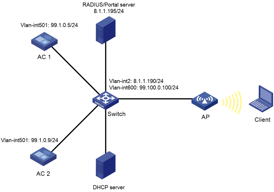
Network configuration
As shown in Figure 1, the AP and the client obtain IP addresses from the DHCP server. The IMC server acts as the portal authentication server, portal Web server, RADIUS server, and MAC binding server.
Configure the devices to meet the following requirements:
· The AP associates with both ACs and the two ACs to back up each other. When the master AC (AC 1) fails, the backup AC (AC 2) takes over, and the AP can provide services correctly through the backup AC.
· Remote MAC authentication and direct portal authentication are used for wireless clients.
· Before passing portal authentication, the client can access only the portal Web server. After passing the authentication, the client can access other network resources.
· The AP forwards all the client traffic.
· The client can access network resources through any Layer 2 ports in its access VLAN without re-authentication.
· The authentication process is simplified and clients do not need to enter username and password every time a client attempts to access network resources.
Analysis
· To allow an authenticated user to access network resources on any Layer 2 ports in its access VLAN without re-authentication, you must enable the portal roaming feature.
· To assign interface GigabitEthernet 1/0/1 on the AP to VLAN 600 for local forwarding, you must edit the configuration file of the AP and then upload the file to the storage medium of the AC.
· To allow clients whose MAC information has been recorded by the RADIUS server to access network resources directly without being portal authenticated, configure the AC to ignore MAC authentication failures.
Restrictions and guidelines
When you configure MAC-based portal authentication for dual-link AC backup and local forwarding, follow these restrictions and guidelines:
· Use the serial ID labeled on the AP's rear panel to specify an AP.
· If you configure manual APs, make sure the manual APs configured on the two ACs have the same AP name and identifier (serial ID or MAC address).
· Make sure the two ACs are of the same version.
· Make sure the portal authentication server type and portal Web server type configured on the ACs are the same as the actual server type. This example uses an IMC server.
· To avoid possible authentication failure caused by frequent logins and logouts of portal clients in a short time, disable the Rule ARP entry feature.
· To allow the RADIUS server to modify user authorization information and log off users, enable the RADIUS session-control feature.
· URLs redirected from the ACs to the portal Web server do not carry parameters by default. You can configure the parameters to carry as needed.
· If you enable portal authentication in VLAN interface view, only centralized forwarding is supported. If you enable portal authentication in service template view, both centralized forwarding and local forwarding are supported. This example enables portal authentication in service template view.
· In a local-forwarding WLAN, the AC does not keep ARP entries for portal clients. To ensure that valid users can perform portal authentication, you must enable wireless client validity check on the AC.
· Make sure the two ACs have the same portal-free rule settings, including the rule numbers.
· Make sure the two ACs have the same portal authentication settings, except for the portal Web server, portal BAS-IP, and interface used by clients to access the AC during portal authentication.
· Some clients are enabled with MAC randomization by default, which might cause seamless roaming failures. As a best practice, disable MAC randomization.
· You must upload the AP configuration file to both the master and backup ACs.
Procedures
Editing the AP configuration file
# Use a text editor to edit the AP configuration file, name the file map.txt, and then upload the file to the storage medium of the ACs. The file content and format are as follows:
system-view
vlan 600
interface gigabitethernet1/0/1
port link-type trunk
port trunk permit vlan 600
Configuring AC 1
1. Configure the VLAN interface:
# Create VLAN 501 and VLAN-interface 501. Assign the VLAN interface an IP address. The AC will use this IP address to establish a CAPWAP tunnel with the AP.
<AC1> system-view
[AC1] vlan 501
[AC1-vlan501] quit
[AC1] interface vlan-interface 501
[AC1-Vlan-interface501] ip address 99.1.0.5 24
[AC1-Vlan-interface501] quit
# Configure GigabitEthernet 1/0/1 that connects AC 1 to the switch as a trunk port, and assign the port to VLANs 501 and 600.
[AC1] interface gigabitethernet 1/0/1
[AC1-GigabitEthernet1/0/1] port link-type trunk
[AC1-GigabitEthernet1/0/1] port trunk permit vlan 501 600
[AC1-GigabitEthernet1/0/1] quit
2. Configure dual-link backup:
# Create AP ap1, and specify the AP name and serial ID.
[AC1] wlan ap ap1 model WA5320
[AC1-wlan-ap-ap1] serial-id 219801A0YH8166E00027
# Set the AP connection priority to 7.
[AC1-wlan-ap-ap1] priority 7
# Specify AC 2 as the backup AC for AC 1.
[AC1-wlan-ap-ap1] backup-ac ip 99.1.0.9
# Enable master CAPWAP tunnel preemption.
[AC1-wlan-ap-ap1] wlan tunnel-preempt enable
[AC1-wlan-ap-ap1] quit
3. Configure a static route to the IMC server.
[AC1] ip route-static 8.1.1.0 255.255.255.0 99.1.0.100
4. Configure wireless services:
# Create service template st1 and enter its view.
[AC1] wlan service-template st1
# Specify the SSID as service.
[AC1-wlan-st-st1] ssid service
# Assign clients coming online through the service template to VLAN 600.
[AC1-wlan-st-st1] vlan 600
# Configure the AP to forward client traffic.
[AC1–wlan-st-st1] client forwarding-location ap
[AC1-wlan-st-st1] quit
# Enter AP view of AP ap1, and deploy configuration file map.txt to the AP.
[AC1] wlan ap ap1
[AC1-wlan-ap-ap1] map-configuration map.txt
# Enter radio view of radio 2.
[AC1-wlan-ap-ap1] radio 2
# Bind service template st1 to radio 2 and enable the radio.
[AC1-wlan-ap-ap1-radio-2] service-template st1
[AC1-wlan-ap-ap1-radio-2] radio enable
[AC1-wlan-ap-ap1-radio-2] quit
[AC1-wlan-ap-ap1] quit
5. Configure a RADIUS scheme:
# Create RADIUS scheme rs1.
[AC1] radius scheme rs1
# Specify the IP addresses of the primary authentication and accounting RADIUS servers.
[AC1-radius-rs1] primary authentication 8.1.1.195
[AC1-radius-rs1] primary accounting 8.1.1.195
# Specify shared keys for RADIUS authentication and accounting.
[AC1-radius-rs1] key authentication simple radius
[AC1-radius-rs1] key accounting simple radius
# Configure AC 1 to remove the ISP domain name from the usernames sent to the RADIUS servers.
[AC1-radius-rs1] user-name-format without-domain
[AC1-radius-rs1] nas-ip 99.1.0.5
[AC1-radius-rs1] quit
# Enable RADIUS session-control.
[AC1] radius session-control enable
6. Configure the authentication domain for portal authentication:
# Create domain dm1 and enter its view.
[AC1] domain dm1
# Configure the domain to use RADIUS scheme rs1 for authentication, authorization, and accounting.
[AC1-isp-dm1] authentication portal radius-scheme rs1
[AC1-isp-dm1] authorization portal radius-scheme rs1
[AC1-isp-dm1] accounting portal radius-scheme rs1
# Set the client idle timeout to 15 minutes and set the minimum threshold to 1024 bytes for clients in ISP domain dm1.
[AC1-isp-dm1] authorization-attribute idle-cut 15 1024
[AC1-isp-dm1] quit
7. Configure the authentication domain for MAC authentication:
# Create ISP domain newpt and enter its view.
[AC1] domain dm2
# Configure the domain to use RADIUS scheme rs1 for authentication, authorization, and accounting for LAN users.
[AC1-isp-dm2] authentication lan-access radius-scheme rs1
[AC1-isp-dm2] authorization lan-access radius-scheme rs1
[AC1-isp-dm2] accounting lan-access radius-scheme rs1
[AC1-isp-dm2] quit
8. Configure portal authentication:
# Create the portal authentication server newpt, specify the server IP address as 8.1.1.195, and set the destination UDP port number to 50100 for the AC to send unsolicited portal packets to the portal authentication server.
[AC1] portal server newpt
[AC1-portal-server-newpt] ip 8.1.1.195 key simple portal
[AC1-portal-server-newpt] port 50100
[AC1-portal-server-newpt] quit
# Configure the URL for the portal Web server newpt as http://8.1.1.195:8080/portal.
[AC1] portal web-server newpt
[AC1-portal-websvr-newpt] url http://8.1.1.195:8080/portal
[AC1-portal-websvr-newpt] quit
# Configure an IPv4-based portal-free rule to permit portal Web server traffic.
[AC1] portal free-rule 0 destination ip 8.1.1.195 24
# Configure IPv4-based portal-free rules to permit DNS server traffic.
[AC1] portal free-rule 1 destination ip any udp 53
[AC1] portal free-rule 2 destination ip any tcp 53
# Enable intra-VLAN roaming for portal users.
[AC1] portal roaming enable
# Disable the Rule ARP entry feature for portal clients.
[AC1] undo portal refresh arp enable
# Enable validity check on wireless portal clients.
[AC1] portal host-check enable
# Enable direct IPv4 portal authentication for service template st1.
[AC1] wlan service-template st1
[AC1-wlan-st-st1] portal enable method direct
# Configure the authentication domain for IPv4 portal users as dm1 on service template st1.
[AC1-wlan-st-st1] portal domain dm1
# Specify portal Web server newpt on service template st1 to redirect portal user HTTP or HTTPS requests to the server.
[AC1-wlan-st-st1] portal apply web-server newpt
# Specify the BAS IP as the IP address of VLAN-interface 501, from which clients come online from AC 1.
[AC1-wlan-st-st1] portal bas-ip 99.1.0.5
9. Configure MAC authentication:
# Set the authentication mode to mac.
[AC1-wlan-st-st1] client-security authentication-mode mac
# Configure the AC to ignore MAC authentication failures.
[AC1-wlan-st-st1] client-security ignore-authentication
# Specify ISP domain dm2 as the authentication domain for MAC authentication clients in service template st1.
[AC1-wlan-st-st1] mac-authentication domain dm2
# Enable the service template.
[AC1-wlan-st-st1] service-template enable
[AC1-wlan-st-st1] quit
Configuring AC 2
1. Configure the VLAN interface:
# Create VLAN 501 and VLAN-interface 501. Assign the VLAN interface an IP address. The AC will use this IP address to establish a CAPWAP tunnel with the AP.
<AC2> system-view
[AC2] vlan 501
[AC2-vlan501] quit
[AC2] interface Vlan-interface 501
[AC2-Vlan-interface501] ip address 99.1.0.9 24
[AC2-Vlan-interface501] quit
# Configure GigabitEthernet 1/0/1 that connects AC 2 to the switch as a trunk port, and assign the port to VLANs 501 and 600.
[AC2] interface gigabitethernet 1/0/1
[AC2-GigabitEthernet1/0/1] port link-type trunk
[AC2-GigabitEthernet1/0/1] port trunk permit vlan 501 600
[AC2-GigabitEthernet1/0/1] quit
2. Configure dual-link backup:
# Create AP ap1, and specify the AP name and serial ID.
[AC2] wlan ap ap1 model WA5320
[AC2-wlan-ap-ap1] serial-id 219801A0YH8166E00027
# Set the AP connection priority to 5.
[AC2-wlan-ap-ap1] priority 5
# Specify AC 1 as the backup AC for AC 2.
[AC2-wlan-ap-ap1] backup-ac ip 99.1.0.5
# Enable master CAPWAP tunnel preemption.
[AC2-wlan-ap-ap1] wlan tunnel-preempt enable
[AC2-wlan-ap-ap1] quit
3. Configure a static route to the IMC server.
[AC2] ip route-static 8.1.1.0 255.255.255.0 99.1.0.100
4. Configure wireless services:
# Create service template st1 and enter its view.
[AC2] wlan service-template st1
# Specify the SSID as service.
[AC2-wlan-st-st1] ssid service
# Assign clients coming online through the service template to VLAN 600.
[AC2-wlan-st-st1] vlan 600
# Configure the AP to forward client traffic.
[AC2–wlan-st-st1] client forwarding-location ap
[AC2-wlan-st-st1] quit
# Enter AP view of AP ap1, and deploy configuration file map.txt to the AP.
[AC2] wlan ap ap1
[AC2-wlan-ap-ap1] map-configuration map.txt
# Enter radio view of radio 2.
[AC2-wlan-ap-ap1] radio 2
# Bind service template st1 to radio 2 and enable the radio.
[AC2-wlan-ap-ap1-radio-2] service-template st1
[AC2-wlan-ap-ap1-radio-2] radio enable
[AC2-wlan-ap-ap1-radio-2] quit
[AC2-wlan-ap-ap1] quit
5. Configure a RADIUS scheme:
# Create RADIUS scheme rs1.
[AC2] radius scheme rs1
# Specify the IP addresses of the primary authentication and accounting RADIUS servers.
[AC2-radius-rs1] primary authentication 8.1.1.195
[AC2-radius-rs1] primary accounting 8.1.1.195
# Specify shared keys for RADIUS authentication and accounting.
[AC2-radius-rs1] key authentication simple radius
[AC2-radius-rs1] key accounting simple radius
# Configure AC 1 to remove the ISP domain name from the usernames sent to the RADIUS servers.
[AC2-radius-rs1] user-name-format without-domain
[AC2-radius-rs1] nas-ip 99.1.0.9
[AC2-radius-rs1] quit
# Enable RADIUS session-control.
[AC2] radius session-control enable
6. Configure the authentication domain for portal authentication:
# Create domain dm1 and enter its view.
[AC2] domain dm1
# Configure the domain to use RADIUS scheme rs1 for authentication, authorization, and accounting.
[AC2-isp-dm1] authentication portal radius-scheme rs1
[AC2-isp-dm1] authorization portal radius-scheme rs1
[AC2-isp-dm1] accounting portal radius-scheme rs1
# Set the client idle timeout to 15 minutes and set the minimum threshold to 1024 bytes for clients in ISP domain dm1.
[AC2-isp-dm1] authorization-attribute idle-cut 15 1024
[AC2-isp-dm1] quit
7. Configure the authentication domain for MAC authentication:
# Create ISP domain newpt and enter its view.
[AC2] domain dm2
# Configure the domain to use RADIUS scheme rs1 for authentication, authorization, and accounting for LAN users.
[AC2-isp-dm2] authentication lan-access radius-scheme rs1
[AC2-isp-dm2] authorization lan-access radius-scheme rs1
[AC2-isp-dm2] accounting lan-access radius-scheme rs1
[AC2-isp-dm2] quit
8. Configure portal authentication:
# Create the portal authentication server newpt, specify the server IP address as 8.1.1.195, and set the destination UDP port number to 50100 for the AC to send unsolicited portal packets to the portal authentication server.
[AC2] portal server newpt
[AC2-portal-server-newpt] ip 8.1.1.195 key simple portal
[AC2-portal-server-newpt] port 50100
[AC2-portal-server-newpt] quit
# Configure the URL for the portal Web server newpt as http://8.1.1.195:8080/portal.
[AC2] portal web-server newpt
[AC2-portal-websvr-newpt] url http://8.1.1.195:8080/portal
[AC2-portal-websvr-newpt] quit
# Configure an IPv4-based portal-free rule to permit portal Web server traffic.
[AC2] portal free-rule 0 destination ip 8.1.1.195 24
# Configure IPv4-based portal-free rules to permit DNS server traffic.
[AC2] portal free-rule 1 destination ip any udp 53
[AC2] portal free-rule 2 destination ip any tcp 53
# Enable intra-VLAN roaming for portal users.
[AC2] portal roaming enable
# Disable the Rule ARP entry feature for portal clients.
[AC2] undo portal refresh arp enable
# Enable validity check on wireless portal clients.
[AC2] portal host-check enable
# Enable direct IPv4 portal authentication for service template st1.
[AC2] wlan service-template st1
[AC2-wlan-st-st1] portal enable method direct
# Configure the authentication domain for IPv4 portal users as dm1 on service template st1.
[AC2-wlan-st-st1] portal domain dm1
# Specify portal Web server newpt on service template st1 to redirect user HTTP or HTTPS requests to the server.
[AC2-wlan-st-st1] portal apply web-server newpt
# Specify the BAS IP as the IP address of VLAN-interface 501, from which clients come online from AC 2.
[AC2-wlan-st-st1] portal bas-ip 99.1.0.9
9. Configure MAC authentication:
# Set the authentication mode to mac.
[AC2-wlan-st-st1] client-security authentication-mode mac
# Configure the AC to ignore MAC authentication failures.
[AC2-wlan-st-st1] client-security ignore-authentication
# Specify ISP domain dm2 as the authentication domain for MAC authentication clients in service template st1.
[AC2-wlan-st-st1] mac-authentication domain dm2
# Enable the service template.
[AC2-wlan-st-st1] service-template enable
[AC2-wlan-st-st1] quit
Configuring the switch
# Create VLAN 501 for forwarding CAPWAP tunnel traffic between AC and AP.
<Switch> system-view
[Switch] vlan 501
[Switch-vlan501] quit
# Create VLAN 600 for forwarding client traffic.
[Switch] vlan 600
[Switch-vlan600] quit
# Create VLAN 2 for connecting to the IMC server.
[Switch] vlan 2
[Switch-vlan2] quit
# Add the interface that connects the switch to the IMC server to VLAN 2. (Details not shown.)
# Configure GigabitEthernet 1/0/1 that connects the switch to AC 1 as a trunk port, and assign it to VLAN 501 and VLAN 600.
[Switch] interface gigabitethernet 1/0/1
[Switch-GigabitEthernet1/0/1] port link-type trunk
[Switch-GigabitEthernet1/0/1] port trunk permit vlan 501 600
[Switch-GigabitEthernet1/0/1] quit
# Configure GigabitEthernet 1/0/3 that connects the switch to AC 2 as a trunk port, and assign it to VLAN 501 and VLAN 600.
[Switch] interface gigabitethernet 1/0/3
[Switch-GigabitEthernet1/0/3] port link-type trunk
[Switch-GigabitEthernet1/0/3] port trunk permit vlan 501 600
[Switch-GigabitEthernet1/0/3] quit
# Configure GigabitEthernet 1/0/2 that connects the switch to the AP as a trunk port, and assign it to VLAN 501 and VLAN 600.
[Switch] interface gigabitethernet 1/0/2
[Switch-GigabitEthernet1/0/2] port link-type trunk
[Switch-GigabitEthernet1/0/2] port trunk permit vlan 501 600
[Switch-GigabitEthernet1/0/2] port trunk pvid vlan 501
# Enable PoE.
[Switch-GigabitEthernet1/0/2] poe enable
[Switch-GigabitEthernet1/0/2] quit
# Configure GigabitEthernet 1/0/4 that connects the switch to the DHCP server as a trunk port, and assign it to VLAN 501 and VLAN 600.
[Switch] interface gigabitethernet 1/0/4
[Switch-GigabitEthernet1/0/4] port link-type trunk
[Switch-GigabitEthernet1/0/4] port trunk permit vlan 501 600
[Switch-GigabitEthernet1/0/4] quit
# Assign an IP address to VLAN-interface 501.
[Switch] interface vlan-interface 501
[Switch-Vlan-interface501] ip address 99.1.0.100 255.255.255.0
[Switch-Vlan-interface501] quit
# Assign an IP address to VLAN-interface 600.
[Switch] interface vlan-interface 600
[Switch-Vlan-interface600] ip address 99.100.0.100 255.255.255.0
[Switch-Vlan-interface600] quit
# Assign an IP address to VLAN-interface 2. This address will be used as the gateway address for the IMC server.
[Switch] interface vlan-interface 2
[Switch-Vlan-interface2] ip address 8.1.1.190 255.255.255.0
[Switch-Vlan-interface2] quit
Configuring the DHCP server
Details not shown.
Configuring the IMC server
In this example, the IMC server runs IMC PLAT 7.3 (E0504), IMC EIA 7.3 (E0503), and IMC EIP 7.3 (E0503).
Configure the RADIUS server
1. Add AC 1 as an access device:
a. Log in to IMC and click the User tab.
b. From the navigation pane, select User Access Policy > Access Device Management > Access Device.
c. Click Add.
The Add Access Device page opens.
d. In the Access Configuration area, configure the following parameters:
- Enter radius in the Shared Key and Confirm Shared Key fields. Make sure the key is the same as the key configured on the ACs.
- Use the default values for other parameters.
e. In the Device List area, click Select or Add Manually to add AC 1 at 99.1.0.5 as an access device.
f. Click OK.
Figure 2 Adding an access device
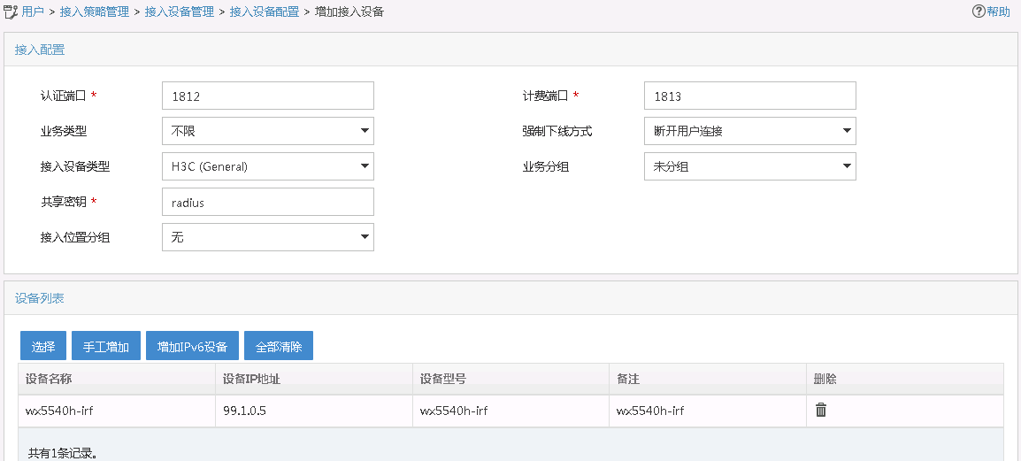
2. Repeat the previous step to add AC 2 as an access device.
The IP address of AC 2 is 99.1.0.9.
Configure the portal server
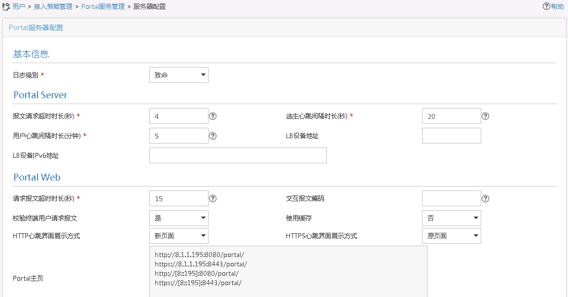
1. Configure portal authentication:
a. Click the User tab.
b. Select User Access Policy > Portal Service > Server from the navigation tree to open the portal server configuration page.
c. Configure the portal server parameters as needed.
This example uses the default settings.
d. Click OK.
Figure 3 Portal authentication server configuration
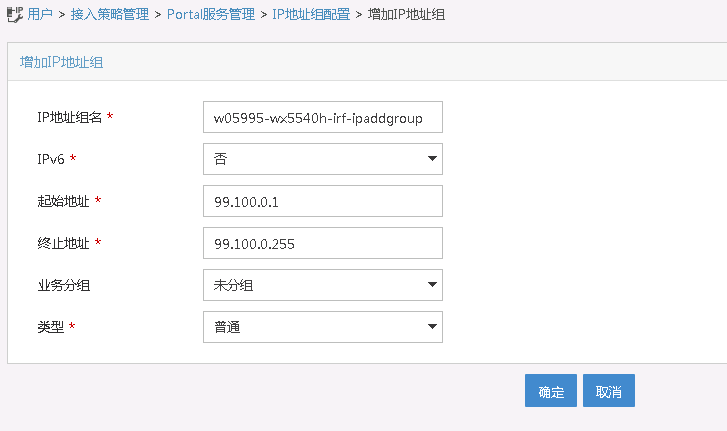
2. Configure the IP address group:
a. Select User Access Policy > Portal Service > IP Group from the navigation tree to open the portal IP address group configuration page.
b. Click Add to open the page as shown in Figure 4.
c. Enter the IP group name.
d. Enter the start IP address and end IP address of the IP group.
Make sure the client IP address is in the IP group.
e. Select a service group.
This example uses the default group Ungrouped.
f. Select Normal from the Action list.
g. Click OK.
Figure 4 Adding an IP address group
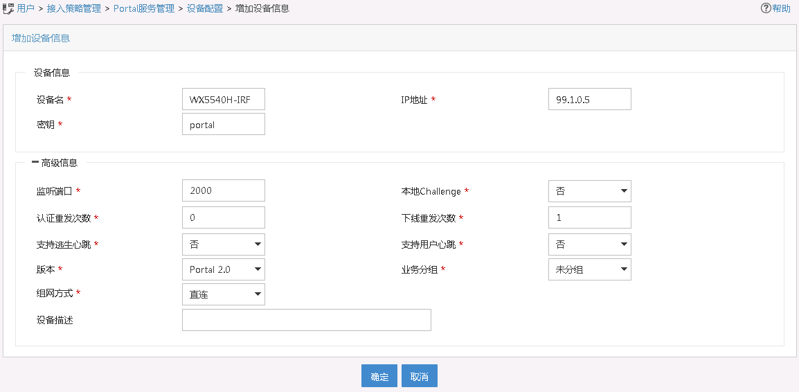
3. Add AC 1 as a portal device:
a. Select User Access Policy > Portal Service > Device from the navigation tree to open the portal device configuration page.
b. Click Add to open the page as shown in Figure 5.
c. Enter the device name.
d. Specify the version as Portal 2.0.
e. Enter the portal BAS-IP configured on AC 1 as the IP address.
f. Set whether to support the portal server heartbeat and user heartbeat functions.
In this example, select No for both Support Server Heartbeat and Support User Heartbeat.
g. Enter the key, which must be the same as that configured on the AC.
h. Select Directly Connected from the Access Method list.
i. Use the default settings for other parameters.
j. Click OK.
Figure 5 Adding a portal device
4. Repeat the previous step to add AC 2 as a portal device.
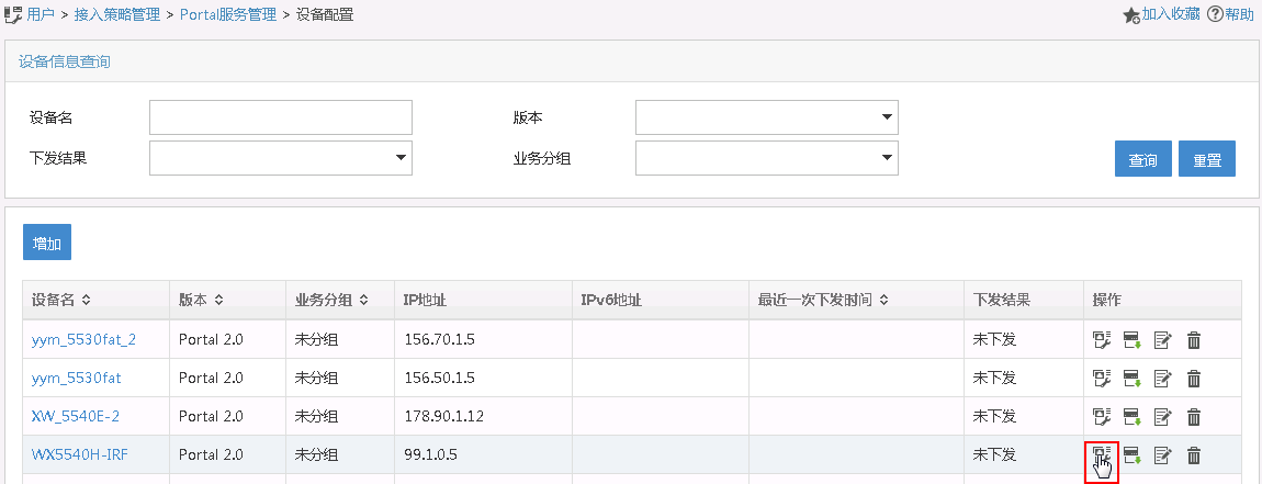
5. Associate AC 1 with the IP address group:
a. As shown in Figure 6, click
the Port Group Information Management icon ![]() for the device to
open the port group configuration page.
for the device to
open the port group configuration page.
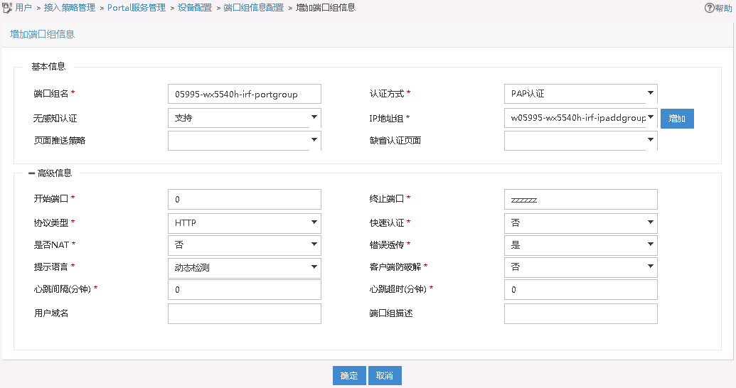
b. Click Add to open the page as shown in Figure 7.
c. Enter the port group name.
d. Select the configured IP address group.
The IP address used by the user to access the network must be within this IP address group.
e. Select Supported for Transparent Authentication.
f. Use the default settings for other parameters.
g. Click OK.
6. Repeat the previous step to associate AC 2 with the IP address group.
Configuring access settings
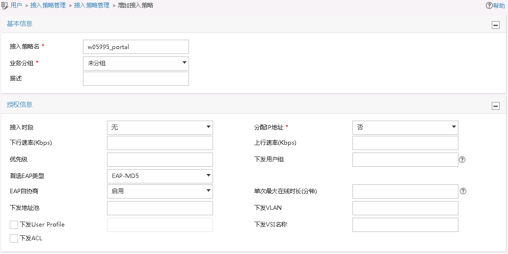
1. Add an access policy:
a. Select User Access Policy > Access Policy from the navigation tree to open the access policy page.
b. Click Add to open the page as shown in Figure 8.
c. Enter the access policy name. In this example, the name is w05995_portal.
d. Select a service group.
e. Use the default settings for other parameters.
f. Click OK.
Figure 8 Adding an access policy
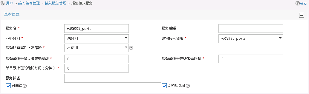
2. Add an access service:
a. Select User Access Policy > Access Service from the navigation tree to open the access service page.
b. Click Add to open the page as shown in Figure 9.
c. Enter the service name. In this example, the service name is w05995_portal.
d. Select the Transparent Authentication on Portal Endpoints option.
e. Use the default settings for other parameters.
f. Click OK.
Figure 9 Adding an access service
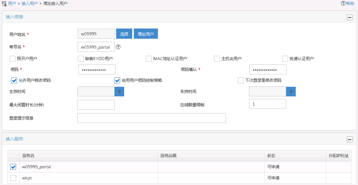
3. Add an access user:
a. Select Access User > All Access Users from the navigation tree to open the access user page.
b. Click Add to open the page as shown in Figure 10.
c. Select or add an access user.
d. Set the password. In this example, the password is w05995_portal.
e. Retain the default settings for other parameters.
f. Click OK.
Figure 10 Adding an access user
4. Configure system parameters:
a. Select User Access Policy > Service Parameters > System Settings from the navigation tree to open the system settings page.
b. Click the Configure
icon ![]() for User Endpoint Settings to open the page as shown in Figure 11.
for User Endpoint Settings to open the page as shown in Figure 11.
c. Enable Transparent MAC Authentication.
d. Select whether to enable transparent portal authentication on non-smart devices.
In this example, select Enable for Non-Terminal Authentication.
e. Click OK.
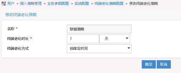
f. Click the Configure
icon ![]() for Endpoint Aging Time to open the page as shown in Figure 12.
for Endpoint Aging Time to open the page as shown in Figure 12.
g. Set the endpoint aging time as needed.
This example uses the default value.
Figure 11 Configuring user endpoint settings
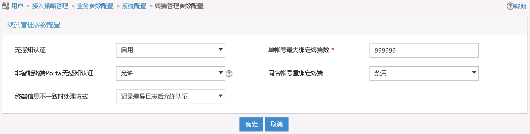
Figure 12 Setting the endpoint aging time
Verifying the configuration
Verifying dual-link backup configuration
# Make the AP come online.
# Verify that the AP first associates with AC 1. Shut down VLAN-interface 501 on AC 1, wait 3 minutes, and verify that the AP associates with AC 2 and the AP state on AC 2 is R/M.
# Bring up VLAN-interface 501 on AC 1. Verify that the AP state becomes R/M on AC 1 and R/B on AC 2.
Verifying transparent MAC authentication configuration
# If user and client MAC address information is not recorded on the RADIUS server, MAC authentication fails. Verify that the AC ignores the authentication failure and triggers portal authentication.
[AC1] display portal user all
Total portal users: 1
Username: w05995_portal
AP name: ap1
Radio ID: 2
SSID: service
Portal server: newpt
State: Online
VPN instance: N/A
MAC IP VLAN Interface
a89c-ed90-7730 99.100.0.12 600 WLAN-BSS2/0/2141
Authorization information:
DHCP IP pool: N/A
User profile: N/A
Session group profile: N/A
ACL number: N/A
Inbound CAR: N/A
Outbound CAR: N/A
After portal authentication, the RADIUS server records user and client MAC address information. At next associations, the client can pass MAC authentication and access network resources without passing portal authentication.
# Display MAC-authenticated user information.
[AC1] display mac-authentication connection
Total connections: 1
User MAC address : c486-e95f-033f
AP name : ap1
Radio ID : 2
SSID : 05995-service-mac
BSSID : 600b-03fc-46d1
Username : c486e95f033f
Authentication domain : dm2
Initial VLAN : 600
Authorization VLAN : 600
Authorization ACL number : N/A
Authorization user profile : N/A
Authorization CAR : N/A
Authorization URL : N/A
Termination action : Default
Session timeout last from : 2019/10/17 19:09:48
Session timeout period : 86400 s
Online from : 2019/10/17 19:09:48
Online duration : 0h 0m 20s
Configuration files
· AC 1:
#
vlan 501
#
wlan service-template st1
ssid service
vlan 600
client forwarding-location ap
client-security authentication-mode mac
client-security ignore-authentication
mac-authentication domain dm2
portal enable method direct
portal domain dm1
portal bas-ip 99.1.0.5
portal apply web-server newpt
service-template enable
#
interface Bridge-Aggregation1
#
interface Vlan-interface501
ip address 99.1.0.5 255.255.255.0
#
interface GigabitEthernet1/0/1
port link-type trunk
port trunk permit vlan 1 501 600
#
ip route-static 8.1.1.0 24 99.1.0.100
#
radius session-control enable
#
radius scheme rs1
primary authentication 8.1.1.195
primary accounting 8.1.1.195
key authentication cipher $c$3$/Mc+yQtK3k6E3L0TtJth+7Pel1EBrSZAmg==
key accounting cipher $c$3$WoQkH/FblsUGadr043yY0MGAPHWTIQvUdA==
user-name-format without-domain
nas-ip 99.1.0.5
#
domain dm1
authorization-attribute idle-cut 15 1024
authentication portal radius-scheme rs1
authorization portal radius-scheme rs1
accounting portal radius-scheme rs1
#
domain dm2
authentication lan-access radius-scheme rs1
authorization lan-access radius-scheme rs1
accounting lan-access radius-scheme rs1
#
portal host-check enable
portal free-rule 0 destination ip 8.1.1.0 255.255.255.0
portal free-rule 1 destination ip any udp 53
portal free-rule 2 destination ip any tcp 53
#
portal web-server newpt
url http://8.1.1.195:8080/portal
#
portal server newpt
ip 8.1.1.195 key cipher $c$3$GZf8+GypB2tLYA25pKOLrJu3quh+vnFElQ==
#
wlan ap ap1 model WA5320
serial-id 219801A0YH8166E00027
wlan tunnel-preempt enable
priority 7
backup-ac ip 99.1.0.9
map-configuration flash:/map.txt
radio 1
radio 2
radio enable
service-template st1
#
· AC 2:
#
vlan 501
#
wlan service-template st1
ssid service
vlan 600
client forwarding-location ap
client-security authentication-mode mac
client-security ignore-authentication
mac-authentication domain dm2
portal enable method direct
portal domain dm1
portal bas-ip 99.1.0.9
portal apply web-server newpt
service-template enable
#
interface Bridge-Aggregation1
#
interface Vlan-interface501
ip address 99.1.0.9 255.255.255.0
#
interface GigabitEthernet1/0/1
port link-type trunk
port trunk permit vlan 1 501 600
#
ip route-static 8.1.1.0 24 99.1.0.100
#
radius session-control enable
#
radius scheme rs1
primary authentication 8.1.1.195
primary accounting 8.1.1.195
key authentication cipher $c$3$/Mc+yQtK3k6E3L0TtJth+7Pel1EBrSZAmg==
key accounting cipher $c$3$WoQkH/FblsUGadr043yY0MGAPHWTIQvUdA==
user-name-format without-domain
nas-ip 99.1.0.9
#
domain dm1
authorization-attribute idle-cut 15 1024
authentication portal radius-scheme rs1
authorization portal radius-scheme rs1
accounting portal radius-scheme rs1
#
domain dm2
authentication lan-access radius-scheme rs1
authorization lan-access radius-scheme rs1
accounting lan-access radius-scheme rs1
#
portal host-check enable
portal free-rule 0 destination ip 8.1.1.0 255.255.255.0
portal free-rule 1 destination ip any udp 53
portal free-rule 2 destination ip any tcp 53
#
portal web-server newpt
url http://8.1.1.195:8080/portal
#
portal server newpt
ip 8.1.1.195 key cipher $c$3$GZf8+GypB2tLYA25pKOLrJu3quh+vnFElQ==
#
wlan ap ap1 model WA5320
serial-id 219801A0YH8166E00027
wlan tunnel-preempt enable
priority 5
backup-ac ip 99.1.0.5
map-configuration flash:/map.txt
radio 1
radio 2
radio enable
service-template st1
#
· Switch:
#
vlan 2
#
vlan 501
#
vlan 600
#
interface Vlan-interface2
ip address 8.1.1.190 255.255.255.0
#
interface Vlan-interface501
ip address 99.1.0.100 255.255.255.0
#
interface Vlan-interface600
ip address 99.100.0.100 255.255.255.0
#
interface GigabitEthernet1/0/1
port link-type trunk
port trunk permit vlan 1 501 600
#
interface GigabitEthernet1/0/2
port link-type trunk
port trunk permit vlan 1 501 600
port trunk pvid vlan 501
poe enable
#
interface GigabitEthernet1/0/3
port link-type trunk
port trunk permit vlan 1 501 600
#
interface GigabitEthernet1/0/4
port link-type trunk
port trunk permit vlan 1 501 600
#
Related documentation
· AAA Management Command Reference in H3C Access Controllers Command References
· AAA Management Configuration Guide in H3C Access Controllers Configuration Guides
· AP Management Command Reference in H3C Access Controllers Command References
· AP Management Configuration Guide in H3C Access Controllers Configuration Guides
· Portal Authentication Command Reference in H3C Access Controllers Command References
· Portal Authentication Configuration Guide in H3C Access Controllers Configuration Guides
· WLAN Access Command Reference in H3C Access Controllers Command References
· WLAN Access Configuration Guide in H3C Access Controllers Configuration Guides
· WLAN High Availability Command Reference in H3C Access Controllers Command References
· WLAN High Availability Configuration Guide in H3C Access Controllers Configuration Guides
