- Table of Contents
-
- 03-CLI configuration examples (AC+fit AP)
- 01-HTTPS Login Configuration Examples
- 02-SSH Configuration Examples
- 03-License Management Configuration Examples
- 04-IPv6 URL Redirection Configuration Examples
- 05-AP Association with the AC at Layer 2 Configuration Examples
- 06-AP Association with the AC at Layer 2 (IPv6) Configuration Examples
- 07-Auto AP Configuration Examples
- 08-AP Association with the AC at Layer 3 Configuration Examples
- 09-AP Association with the AC at Layer 3 (IPv6) Configuration Examples
- 10-WEP Encryption Configuration Examples
- 11-PSK Encryption Configuration Examples
- 12-WPA3-SAE PSK Encryption Configuration Examples
- 13-WLAN Access (IPv6) Configuration Examples
- 14-Policy-Based Forwarding with Dual Gateways Configuration Examples
- 15-Scheduled Configuration Deployment by AP Group Configuration Examples
- 16-Inter-AC Roaming with Static Client VLAN Allocation Configuration Examples
- 17-Service Template and Radio Binding Configuration Examples
- 18-Scheduled WLAN Access Services Configuration Examples
- 19-Local Portal Authentication Configuration Examples
- 20-HTTPS-Based Local Portal Authentication Configuration Examples
- 21-Remote Portal Authentication Configuration Examples
- 22-Local Portal Authentication through LDAP Server Configuration Examples
- 23-Local Portal Authentication and SSID-based Authentication Page Pushing Configuration Examples
- 24-Local Portal MAC-Trigger Authentication Configuration Examples
- 25-Portal MAC-Trigger Authentication Configuration Examples
- 26-Local Forwarding Mode and Local Portal MAC-Trigger Authentication Configuration Examples
- 27-Local Portal Authentication (IPv6) Configuration Examples
- 28-Local Portal Authentication through LDAP Server (IPv6) Configuration Examples
- 29-Remote Portal Authentication (IPv6) Configuration Examples
- 30-Portal MAC-Trigger Authentication (IPv6) Configuration Example
- 31-Remote Portal Authentication with User Profile Authorization Configuration Examples
- 32-Portal Fail-Permit Configuration Examples
- 33-Local MAC Authentication Configuration Examples
- 34-MAC Authentication and PSK Authentication Configuration Examples
- 35-Remote MAC and Portal Authentication and Transparent Authentication Configuration Examples
- 36-Remote AP and Remote Portal MAC-Trigger Authentication Configuration Examples
- 37-MAC Authentication with Guest VLAN Assignment Configuration Examples
- 38-MAC Authentication with Guest VLAN Assignment (IPv6) Configuration Examples
- 39-Local MAC-Then-802.1X Authentication Configuration Examples
- 40-Local 802.1X Authentication Configuration Examples
- 41-Local RADIUS-Based 802.1X Authentication in EAP Relay Mode Configuration Examples
- 42-Remote 802.1X Authentication Configuration Examples
- 43-Remote 802.1X Authentication (IPv6) Configuration Examples
- 44-Remote 802.1X Authentication in WPA3-Enterprise Mode Configuration Examples
- 45-802.1X Authentication with ACL Assignment Through IMC Server Configuration Examples
- 46-802.1X Authentication with User Profile Assignment Through IMC Server Configuration Examples
- 47-EAD Authentication Configuration Examples
- 48-EAD Authentication (IPv6) Configuration Examples
- 49-Local Forwarding Mode and Local Portal Authentication Configuration Examples
- 50-Local Forwarding Mode Direct Portal Authentication Configuration Examples
- 51-Local Forwarding Mode Direct Portal Authentication (IPv6) Configuration Examples
- 52-Local Forwarding Configuration Examples
- 53-Remote AP Configuration Examples
- 54-WIPS Configuration Examples
- 55-WIPS Countermeasures Against All SSIDs Configuration Examples
- 56-IP Source Guard (IPv4) Configuration Examples
- 57-IP Source Guard (IPv6) Configuration Examples
- 58-IRF Setup with Members Directly Connected Configuration Examples
- 59-IRF Setup with Members Not Directly Connected Configuration Examples
- 60-IRF Setup with Members in One Chassis Configuration Examples
- 61-IRF Setup with Members in Different Chassis Configuration Examples
- 62-Dual-Link Backup Configuration Examples
- 63-Remote 802.1X Auth on AC Hierarchy Network with Dual-Link Central AC Backup Configuration Examples
- 64-Remote Portal Auth on AC Hierarchy Network with Dual-Link Central AC Backup Configuration Examples
- 65-OAuth-Based Portal MAC-Trigger Auth on Local-Forwarding Dual-Link Backup Configuration Examples
- 66-Dual-Link Backup OAuth-Based Portal Auth in Local Forwarding Configuration Examples
- 67-Dual-Link Backup Remote Portal MAC-Trigger Auth in Local Forwarding Configuration Examples
- 68-Dual-Link Backup Remote Portal and Transparent MAC Auth in Local Forwarding Configuration Examples
- 69-Dual-Link Backup Remote Portal Auth in Local Forwarding Configuration Examples
- 70-Dual-Link Backup Remote Portal and MAC Auth in Centralized Forward Configuration Examples
- 71-Dual-Link Backup Remote Portal Auth in Centralized Forwarding Configuration Examples
- 72-Dual-Link Backup Lightweight Portal Auth in Centralized Forwarding Configuration Examples
- 73-Dual-Link Backup OAuth-Based Portal Auth in Centralized Forwarding Configuration Examples
- 74-Dual-Link Backup Remote Portal MAC-Trigger Auth in Centralized Forwarding Configuration Examples
- 75-Remote 802.1X Auth on a Dual-Link AC Backup Network Configuration Examples
- 76-Remote MAC Auth on a Dual-Link AC Backup Network Configuration Examples
- 77-Remote 802.1X Authentication on an AC Hierarchy Network Configuration Examples
- 78-Remote 802.1X Authentication Configuration Examples
- 79-WLAN Probe Configuration Examples
- 80-Multicast Optimization Configuration Examples
- 81-Client Rate Limiting Configuration Examples
- 82-Inter-AC Roaming Configuration Examples
- 83-Inter-AC Roaming (IPv6) Configuration Examples
- 84-WLAN Load Balancing Configuration Examples
- 85-Static Blacklist Configuration Examples
- 86-Client Quantity Control Configuration Examples
- 87-AP License Synchronization Configuration Examples
- 88-iBeacon Management Configuration Examples
- 89-Mesh Link Establishment Between a Fit AP and a Fat AP Configuration Examples
- 90-Mesh Link Establishment Between Fit APs Configuration Examples
- 91-Auto-DFS and Auto-TPC Configuration Examples
- 92-AP Image Downloading Configuration Examples
- 93-Dual-Uplink Interfaces Configuration Guide
- 94-Internal-to-External Access Through NAT Configuration Examples
- 95-Layer 2 Static Aggregation Configuration Examples
- 96-Layer 2 Multicast Configuration Examples
- 97-Static VLAN Allocation Configuration Examples
- 98-URL Redirection Configuration Examples
- Related Documents
-
| Title | Size | Download |
|---|---|---|
| 78-Remote 802.1X Authentication Configuration Examples | 338.64 KB |
|
|
|
H3C Access Controllers |
|
Comware 7 Remote 802.1X Authentication on an AC Hierarchy Network (Central AC Authentication + AP Forwarding) |
|
Configuration Examples |
|
|
Copyright © 2022 New H3C Technologies Co., Ltd. All rights reserved.
No part of this manual may be reproduced or transmitted in any form or by any means without prior written consent of New H3C Technologies Co., Ltd.
Except for the trademarks of New H3C Technologies Co., Ltd., any trademarks that may be mentioned in this document are the property of their respective owners.
The information in this document is subject to change without notice.
General restrictions and guidelines
Example: Configuring remote 802.1X authentication on an AC hierarchy network
Editing the AP configuration file
Introduction
The following information provides an example of configuring remote 802.1X authentication for clients on a network that deploys an AC hierarchy.
Prerequisites
The following information applies to Comware 7-based access controllers and access points. Procedures and information in the examples might be slightly different depending on the software or hardware version of the access controllers and access points.
The configuration examples were created and verified in a lab environment, and all the devices were started with the factory default configuration. When you are working on a live network, make sure you understand the potential impact of every command on your network.
The following information is provided based on the assumption that you have basic knowledge of AC hierarchy, 802.1X, WLAN access, and AP management features.
General restrictions and guidelines
Central ACs on an AC hierarchy network do not support IRF.
Example: Configuring remote 802.1X authentication on an AC hierarchy network
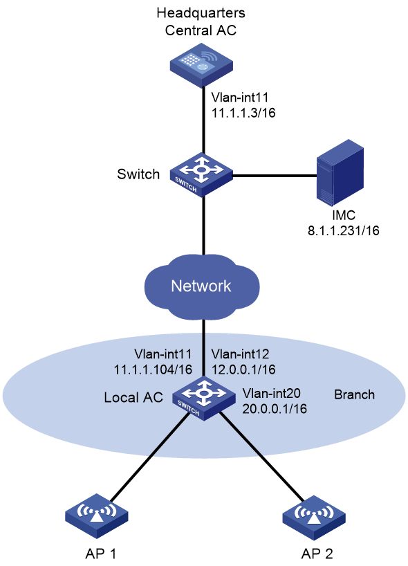
Network configuration
As shown in Figure 1:
· The network deploys an AC hierarchy that contains one central AC and one local AC. The central AC is a wireless access controller and the local AC is a unified wired and wireless access controller. In this example, the APs are connected to the local AC through GigabitEthernet 1/0/1.
· The APs are assigned to VLAN 12 and the clients are assigned to VLAN 20.
· The network deploys a RADIUS server that runs IMC for 802.1X authentication.
Configure the devices to meet the following requirements:
· The APs and clients are associated with the local AC.
¡ The APs obtain the IP address of the central AC through DHCP Option 43.
¡ The AC rediscovery feature is configured on the central AC for the APs to discover the local AC.
· The central AC acts as the authenticator and uses the RADIUS server to perform authentication, authorization, and accounting for the clients. 802.1X authentication is enabled in the service template through which the clients access the network.
· The AP locally forwards client data traffic in VLAN 12.
· The local AC acts as a DHCP server to assign IP addresses to the APs and the clients.
Analysis
For GigabitEthernet 1/0/1 to forward client data traffic in VLAN 12, edit a .txt configuration file and upload the file to the central AC. In the file, the port is added to VLAN 12. Because the clients are assigned to VLAN 20, add the port also to VLAN 20 for the clients to pass RADIUS-based 802.1X authentication and come online.
For an AP to discover the local AC and come online from the local AC, enable the AC rediscovery feature in the view of the manual AP that is created for the AP. In addition, configure the central AC to add the IP address of the local AC to the CAPWAP Control IP Address message element in the discovery responses sent to the AP. If the AC rediscovery feature is not configured for an AP, the central AC will send the IP address of the lightest loaded local AC to the AP. If the lightest loaded local AC is not the local AC in the branch, the AP cannot come online.
Software versions used
This configuration example was created and verified on WX5560H Release 5415P01 on the central AC and WX3510H Release 5415P01 on the local AC.
Restrictions and guidelines
Use the serial ID labeled on the AP's rear panel to specify an AP.
On the local AC, do not enable the auto AP feature. In addition, create a manual AP for each AP in local AC view on the central AC for the central AC to manage the APs.
Prerequisites
Make sure the devices can reach one another.
Procedures
Editing the AP configuration file
# Use a text editor to edit the APs' configuration file, and then upload the file to the central AC. In this example, the configuration file name is map.txt.
The following is the AP configuration for this example:
system-view
vlan 12
vlan 20
interface GigabitEthernet1/0/1
port link-type trunk
port trunk permit vlan 1 12 20
Configuring the central AC
Configuring interfaces
# Create VLAN 11, create VLAN-interface 11, and assign an IP address to the VLAN interface. The AC will use this IP address to establish a management tunnel with the local AC.
<Central AC> system-view
[Central AC] vlan 11
[Central AC-vlan11] quit
[Central AC] interface vlan-interface 11
[Central AC-Vlan-interface11] ip address 11.1.1.3 16
[Central AC-Vlan-interface11] quit
Configuring a local AC for the central AC
# Create local AC 3510h-1 with model WX3510H and enter local AC view.
[Central AC] wlan local-ac name 3510h-1 model WX3510H
# Specify the serial ID of the local AC.
[Central AC-wlan-local-ac-3510h-1] serial-id 210235A1GCH147000017
[Central AC-wlan-local-ac-3510h-1] quit
Configuring RADIUS-based 802.1X authentication
1. Configure a RADIUS scheme:
# Create RADIUS scheme imc and enter its view.
[Central-AC] radius scheme imc
# Specify the IP address of the primary RADIUS authentication server.
[Central AC-radius-imc] primary authentication 8.1.1.231
# Specify the IP address of the primary RADIUS accounting server.
[Central AC-radius-imc] primary accounting 8.1.1.231
# Set the shared key to 12345678 in plaintext form for secure communication with the RADIUS authentication server.
[Central AC-radius-imc] key authentication simple 12345678
# Set the shared key to 12345678 in plaintext form for secure communication with the RADIUS accounting server.
[Central AC-radius-imc] key accounting simple 12345678
# Exclude the domain name from usernames sent to the RADIUS servers.
[Central AC-radius-imc] user-name-format without-domain
# Specify IP address 11.1.1.3 as the source IP address for outgoing RADIUS packets.
[Central AC-radius-imc] nas-ip 11.1.1.3
[Central AC-radius-imc] quit
2. Configure an authentication domain:
# Create ISP domain imc and enter its view.
[Central-AC] domain imc
# Configure the ISP domain to use RADIUS scheme imc for 802.1X user authentication.
[Central-AC-isp-imc] authentication lan-access radius-scheme imc
# Configure the ISP domain to use RADIUS scheme imc for 802.1X user authorization.
[Central-AC-isp-imc] authorization lan-access radius-scheme imc
# Configure the ISP domain to use RADIUS scheme imc for 802.1X user accounting.
[Central-AC-isp-imc] accounting lan-access radius-scheme imc
[Central-AC-isp-imc] quit
3. Configure EAP relay as the method for the AC to exchange packets with the RADIUS server.
[Central-AC] dot1x authentication-method eap
Configuring a service template
# Create service template dot1x and set the SSID of the service template.
[Central-AC] wlan service-template dot1x
[Central-AC-wlan-st-dot1x] ssid dot1x
# Assign VLAN 20 to the matching clients.
[Central-AC-wlan-st-dot1x] vlan 20
# Specify the central AC as the authenticator.
[Central-AC-wlan-st-dot1x] client-security authentication-location central-ac
# Configure APs to forward client data traffic from all VLANs.
[Central-AC-wlan-st-dot1x] client forwarding-location ap
# Set the AKM mode to 802.1X.
[Central-AC-wlan-st-dot1x] akm mode dot1x
# Specify the CCMP cipher suite and enable the RSN IE in beacon and probe responses.
[Central-AC-wlan-st-dot1x] cipher-suite ccmp
[Central-AC-wlan-st-dot1x] security-ie rsn
# Set the access authentication mode to 802.1X authentication.
[Central-AC-wlan-st-dot1x] client-security authentication-mode dot1x
# Specify ISP domain imc for authenticating the 802.1X client.
[Central-AC-wlan-st-dot1x] dot1x domain imc
# Enable the service template.
[Central-AC-wlan-st-dot1x] service-template enable
[Central-AC-wlan-st-dot1x] quit
Creating a manual AP
# Create manual AP ap1 and specify the AP model and serial ID.
[Central AC] wlan ap ap1 model WA5620i-ACN
[Central AC-wlan-ap-ap1] serial-id 210235A1SVC15C000028
# Deploy configuration file map.txt to the manual AP.
[Central-AC-wlan-ap-ap1] map-configuration cfa0:/map.txt
# Enable the AC rediscovery feature.
[Central-AC-wlan-ap-ap1] control-address enable
# Specify 11.1.1.104 (an IP address on the local AC) as the IP address to be carried in the CAPWAP Control IP Address message element.
[Central AC-wlan-ap-ap1] control-address ip 11.1.1.104
# Enable radio 1, and then bind service template dot1x to the radio and specify VLAN 20 for the radio.
[Central AC-wlan-ap-ap1] radio 1
[Central AC-wlan-ap-ap1-radio-1] radio enable
[Central AC-wlan-ap-ap1-radio-1] service-template dot1x vlan 20
[Central AC-wlan-ap-ap1-radio-1] quit
[Central-AC-wlan-ap-ap1] quit
Configuring the local AC
1. Configure the local AC feature:
# Enable the local AC feature.
<Local AC> system-view
[Local AC] wlan local-ac enable
# Specify the central AC for the local AC.
[Local AC] wlan central-ac ip 11.1.1.3
# Configure the local AC to use VLAN 11 to establish CAPWAP tunnels with the central AC.
[Local AC] wlan local-ac capwap source-vlan 11
2. Configure IP address pool settings:
# Enable the DHCP service.
[Local AC] dhcp enable
# Configure DHCP address pool ap. In the address pool, specify 12.0.0.1 as the gateway IP address and 12.0.0.0/16 as the subnet for dynamic allocation.
[Local AC] dhcp server ip-pool ap
[Local AC-dhcp-pool-ap] gateway-list 12.0.0.1
[Local AC-dhcp-pool-ap] network 12.0.0.0 mask 255.255.0.0
# Configure Option 43 to specify the central AC address as the AC address in DHCP address pool ap.
[Local AC-dhcp-pool-ap] option 43 hex 80070000010b010101
[Local AC-dhcp-pool-ap] quit
# Configure DHCP address pool client. In the address pool, specify 20.0.0.1 as the gateway IP address and 20.0.0.0/16 as the subnet for dynamic allocation.
[Local AC] dhcp server ip-pool client
[Local AC-dhcp-pool-client] gateway-list 20.0.0.1
[Local AC-dhcp-pool-client] network 20.0.0.0 mask 255.255.0.0
[Local AC-dhcp-pool-client] quit
3. Configure interfaces:
# Create VLAN 11, create VLAN-interface 11, and assign an IP address to the VLAN interface. The local AC will use this IP address to establish CAPWAP tunnels with the central AC.
[Local AC] vlan 11
[Local AC-vlan11] quit
[Local AC] interface vlan-interface 11
[Local AC-Vlan-interface11] ip address 11.1.1.104 255.255.0.0
[Local AC-Vlan-interface11] quit
# Create VLAN 12, create VLAN-interface 12, and assign an IP address to the VLAN interface. The local AC assigns VLAN 12 to an AP when the AP comes online.
[Local AC] vlan 12
[Local AC-vlan12] quit
[Local AC] interface vlan-interface 12
[Local AC-Vlan-interface12] ip address 12.0.0.1 255.255.0.0
[Local AC-Vlan-interface12] dhcp server apply ip-pool ap
[Local AC-Vlan-interface12] quit
# Create VLAN 20, create VLAN-interface 20, and assign an IP address to the VLAN interface. The local AC assigns this VLAN to a wireless client when the client comes online.
[Local AC] vlan 20
[Local AC-vlan20] quit
[Local AC] interface vlan-interface 20
[Local AC-Vlan-interface20] ip address 20.0.0.1 255.255.0.0
[Local AC-Vlan-interface20] dhcp server apply ip-pool client
[Local AC-Vlan-interface20] quit
Configuring the RADIUS server
Prerequisites
The RADIUS server runs IMC PLAT 7.2 (E0403p10), IMC EIA 7.2 (E0405), and IMC EIP 7.2 (E0405).
Make sure the RADIUS server has been installed with the EAP-PEAP certificate.
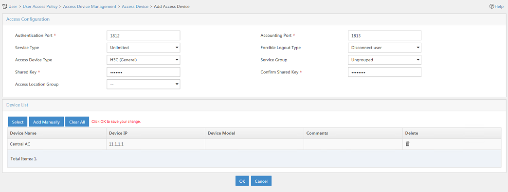
Adding the central AC as an access device to IMC
1. Log in to IMC and click the User tab.
2. From the navigation tree, select User Access Policy > Access Device Management > Access Device.
3. Click Add.
The Add Access Device page opens.
4. In the Access Configuration area, configure the following parameters, as shown in Figure 2:
¡ Enter 12345678 in the Shared Key and Confirm Shared Key fields. The shared key must be the same as the authentication and accounting shared keys configured on the central AC.
¡ Use the default values for other parameters.
5. In the Device List area, click Select or Add Manually to add the central AC at 11.1.1.3 as an access device.
The IP address must be the source IP address specified for outgoing RADIUS packets in the RADIUS scheme on the central AC.
6. Click OK.
Figure 2 Adding an access device
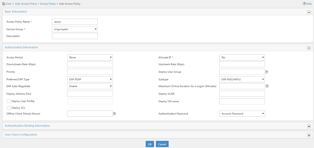
Adding an access policy
1. From the navigation tree, select User Access Policy > Access Policy.
2. Click Add.
3. On the Add Access Policy page, configure the following parameters, as shown in Figure 3:
¡ Enter dot1x in the Access Policy Name field.
¡ Select EAP-PEAP from the Preferred EAP Type list, and select EAP-MSCHAPv2 from the Subtype list.
The certificate subtype on the IMC server must be the same as the identity authentication method configured on the clients.
Figure 3 Adding an access policy
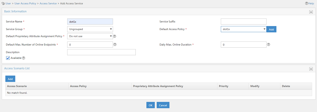
Adding an access service
1. From the navigation tree, select User Access Policy > Access Service.
2. Click Add.
3. On the Add Access Service page, configure the following parameters, as shown in Figure 4:
¡ Enter dot1x in the Service Name field.
¡ Select dot1x from the Default Access Policy list.
4. Click OK.
Figure 4 Adding an access service
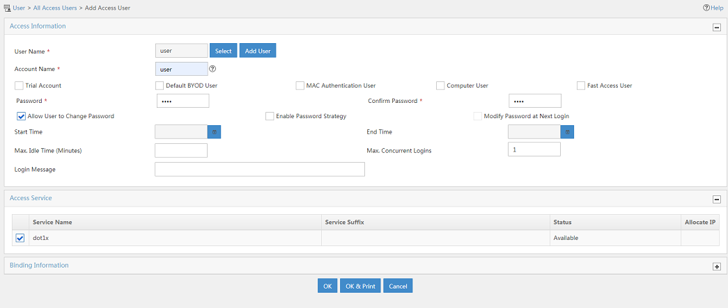
Adding an access user
1. From the navigation tree, select Access User > Access User.
The access user list opens.
2. Click Add.
The Add Access User page opens.
3. In the Access Information area, configure the following parameters, as shown in Figure 5:
a. Click Select or Add User to associate the user with IMC Platform user user.
b. Enter user in the Account Name field.
c. Enter dot1x in the Password and Confirm Password fields.
4. In the Access Service area, select dot1x from the list.
5. Click OK.
Figure 5 Adding an access user account
Verifying the configuration
[Central AC] display wlan local-ac name 3510h-1
Local AC Information
State : I = Idle, J = Join, JA = JoinAck, IL = ImageLoad
C = Config, DC = DataCheck, R = Run
AC name ACID State Model Serial ID
3510h-1 2 R/M WX3510H 210235A1GCH147000017
# Verify that the local AC has established a management tunnel with the central AC. The state of an AP changes to R/M (Run/Master) on the central AC after it comes online from the local AC.
[Central AC] display wlan ap all
Total number of APs: 1
Total number of connected APs: 1
Total number of connected manual APs: 1
Total number of connected auto APs: 0
Total number of connected common APs: 1
Total number of connected WTUs: 0
Total number of inside APs: 0
Maximum supported APs: 4096
Remaining APs: 4095
Total AP licenses: 512
Remaining AP licenses: 511
AP information
State : I = Idle, J = Join, JA = JoinAck, IL = ImageLoad
C = Config, DC = DataCheck, R = Run, M = Master, B = Backup
AP name APID State Model Serial ID
ap1 8 R/M WA5620i-ACN 210235A1SVC15C000028
# On the central AC, verify that the AP has associated with the local AC.
[Central AC] display wlan ap-distribution all
Central AC
Slot : 1
Total Number of APs: 0
AP name :
Local AC
Name : 3510h-1
Total Number of APs: 1
AP name : ap1
# Connect a client to the wireless network to verify that the client can pass 802.1X authentication. (Details not shown.)
# On the central AC, display wireless client information to verify that the client has come online.
[Central AC] display wlan client
Total number of clients: 1
MAC address User name AP name RID IP address VLAN
e49a-dc71-a162 N/A ap1 1 20.0.0.2 20
# On the central AC, display online 802.1X information to verify that the client has passed 802.1X authentication.
[Central AC] display dot1x connection
Total connections: 1
User MAC address : e49a-dc71-a162
AP name : ap1
Radio ID : 1
SSID : dot1x
BSSID : 3891-d59a-7960
Username : user
Authentication domain : imc
IPv4 address : 20.0.0.2
Authentication method : EAP
Initial VLAN : 20
Authorization VLAN : 20
Authorization ACL number : N/A
Authorization user profile : N/A
Termination action : Default
Session timeout period : 86400 s
Online from : 2019/05/22 11:31:18
Online duration : 0h 2m 12s
Configuration files
· Central AC:
#
vlan 11
#
dot1x authentication-method eap
#
wlan service-template dot1x
ssid dot1x
vlan 20
client forwarding-location ap
client-security authentication-location central-ac
akm mode dot1x
cipher-suite ccmp
security-ie rsn
client-security authentication-mode dot1x
dot1x domain imc
service-template enable
#
interface Vlan-interface11
ip address 11.1.1.3 255.255.0.0
#
radius scheme imc
primary authentication 8.1.1.231
primary accounting 8.1.1.231
key authentication cipher $c$3$t7x0fIARso0US949SnQS2pq53eIdsgUr6z07
key accounting cipher $c$3$V4YI3sDOEq0VqAIPoaNjQOV3ZalvqTL05GC0
user-name-format without-domain
nas-ip 11.1.1.3
#
domain imc
authentication lan-access radius-scheme imc
authorization lan-access radius-scheme imc
accounting lan-access radius-scheme imc
#
wlan ap ap1 model WA5620i-ACN
serial-id 210235A1SVC15C000028
map-configuration cfa0:/map.txt
control-address enable
control-address ip 11.1.1.104
radio 1
radio enable
service-template dot1x vlan 20
#
wlan local-ac name 3510h-1 model WX3510H
serial-id 210235A1GCH147000017
#
· Local AC:
#
dhcp enable
#
vlan 11 to 12
#
vlan 20
#
dhcp server ip-pool ap
gateway-list 12.0.0.1
network 12.0.0.0 mask 255.255.0.0
option 43 hex 80070000010b010101
#
dhcp server ip-pool client
gateway-list 20.0.0.1
network 20.0.0.0 mask 255.255.0.0
#
interface Vlan-interface11
ip address 11.1.1.104 255.255.0.0
#
interface Vlan-interface12
ip address 12.0.0.1 255.255.0.0
dhcp server apply ip-pool ap
#
interface Vlan-interface20
ip address 20.0.0.1 255.255.0.0
dhcp server apply ip-pool client
#
wlan local-ac enable
wlan local-ac capwap source-vlan 11
#
wlan central-ac ip 11.1.1.3
Related documentation
· AP and WT Management Configuration Guide in H3C Access Controllers Configuration Guides
· AP and WT Management Command Reference in H3C Access Controllers Command References
· High Availability Configuration Guide in H3C Access Controllers Configuration Guides
· High Availability Command Reference in H3C Access Controllers Command References
· Network Connectivity Configuration Guide in H3C Access Controllers Configuration Guides
· Network Connectivity Command Reference in H3C Access Controllers Command References
· User Access and Authentication Configuration Guide in H3C Access Controllers Configuration Guides
· User Access and Authentication Command Reference in H3C Access Controllers Command References
· WLAN Access Configuration Guide in H3C Access Controllers Configuration Guides
· WLAN Access Command Reference in H3C Access Controllers Command References
