- Table of Contents
-
- 03-CLI configuration examples (AC+fit AP)
- 01-HTTPS Login Configuration Examples
- 02-SSH Configuration Examples
- 03-License Management Configuration Examples
- 04-IPv6 URL Redirection Configuration Examples
- 05-AP Association with the AC at Layer 2 Configuration Examples
- 06-AP Association with the AC at Layer 2 (IPv6) Configuration Examples
- 07-Auto AP Configuration Examples
- 08-AP Association with the AC at Layer 3 Configuration Examples
- 09-AP Association with the AC at Layer 3 (IPv6) Configuration Examples
- 10-WEP Encryption Configuration Examples
- 11-PSK Encryption Configuration Examples
- 12-WPA3-SAE PSK Encryption Configuration Examples
- 13-WLAN Access (IPv6) Configuration Examples
- 14-Policy-Based Forwarding with Dual Gateways Configuration Examples
- 15-Scheduled Configuration Deployment by AP Group Configuration Examples
- 16-Inter-AC Roaming with Static Client VLAN Allocation Configuration Examples
- 17-Service Template and Radio Binding Configuration Examples
- 18-Scheduled WLAN Access Services Configuration Examples
- 19-Local Portal Authentication Configuration Examples
- 20-HTTPS-Based Local Portal Authentication Configuration Examples
- 21-Remote Portal Authentication Configuration Examples
- 22-Local Portal Authentication through LDAP Server Configuration Examples
- 23-Local Portal Authentication and SSID-based Authentication Page Pushing Configuration Examples
- 24-Local Portal MAC-Trigger Authentication Configuration Examples
- 25-Portal MAC-Trigger Authentication Configuration Examples
- 26-Local Forwarding Mode and Local Portal MAC-Trigger Authentication Configuration Examples
- 27-Local Portal Authentication (IPv6) Configuration Examples
- 28-Local Portal Authentication through LDAP Server (IPv6) Configuration Examples
- 29-Remote Portal Authentication (IPv6) Configuration Examples
- 30-Portal MAC-Trigger Authentication (IPv6) Configuration Example
- 31-Remote Portal Authentication with User Profile Authorization Configuration Examples
- 32-Portal Fail-Permit Configuration Examples
- 33-Local MAC Authentication Configuration Examples
- 34-MAC Authentication and PSK Authentication Configuration Examples
- 35-Remote MAC and Portal Authentication and Transparent Authentication Configuration Examples
- 36-Remote AP and Remote Portal MAC-Trigger Authentication Configuration Examples
- 37-MAC Authentication with Guest VLAN Assignment Configuration Examples
- 38-MAC Authentication with Guest VLAN Assignment (IPv6) Configuration Examples
- 39-Local MAC-Then-802.1X Authentication Configuration Examples
- 40-Local 802.1X Authentication Configuration Examples
- 41-Local RADIUS-Based 802.1X Authentication in EAP Relay Mode Configuration Examples
- 42-Remote 802.1X Authentication Configuration Examples
- 43-Remote 802.1X Authentication (IPv6) Configuration Examples
- 44-Remote 802.1X Authentication in WPA3-Enterprise Mode Configuration Examples
- 45-802.1X Authentication with ACL Assignment Through IMC Server Configuration Examples
- 46-802.1X Authentication with User Profile Assignment Through IMC Server Configuration Examples
- 47-EAD Authentication Configuration Examples
- 48-EAD Authentication (IPv6) Configuration Examples
- 49-Local Forwarding Mode and Local Portal Authentication Configuration Examples
- 50-Local Forwarding Mode Direct Portal Authentication Configuration Examples
- 51-Local Forwarding Mode Direct Portal Authentication (IPv6) Configuration Examples
- 52-Local Forwarding Configuration Examples
- 53-Remote AP Configuration Examples
- 54-WIPS Configuration Examples
- 55-WIPS Countermeasures Against All SSIDs Configuration Examples
- 56-IP Source Guard (IPv4) Configuration Examples
- 57-IP Source Guard (IPv6) Configuration Examples
- 58-IRF Setup with Members Directly Connected Configuration Examples
- 59-IRF Setup with Members Not Directly Connected Configuration Examples
- 60-IRF Setup with Members in One Chassis Configuration Examples
- 61-IRF Setup with Members in Different Chassis Configuration Examples
- 62-Dual-Link Backup Configuration Examples
- 63-Remote 802.1X Auth on AC Hierarchy Network with Dual-Link Central AC Backup Configuration Examples
- 64-Remote Portal Auth on AC Hierarchy Network with Dual-Link Central AC Backup Configuration Examples
- 65-OAuth-Based Portal MAC-Trigger Auth on Local-Forwarding Dual-Link Backup Configuration Examples
- 66-Dual-Link Backup OAuth-Based Portal Auth in Local Forwarding Configuration Examples
- 67-Dual-Link Backup Remote Portal MAC-Trigger Auth in Local Forwarding Configuration Examples
- 68-Dual-Link Backup Remote Portal and Transparent MAC Auth in Local Forwarding Configuration Examples
- 69-Dual-Link Backup Remote Portal Auth in Local Forwarding Configuration Examples
- 70-Dual-Link Backup Remote Portal and MAC Auth in Centralized Forward Configuration Examples
- 71-Dual-Link Backup Remote Portal Auth in Centralized Forwarding Configuration Examples
- 72-Dual-Link Backup Lightweight Portal Auth in Centralized Forwarding Configuration Examples
- 73-Dual-Link Backup OAuth-Based Portal Auth in Centralized Forwarding Configuration Examples
- 74-Dual-Link Backup Remote Portal MAC-Trigger Auth in Centralized Forwarding Configuration Examples
- 75-Remote 802.1X Auth on a Dual-Link AC Backup Network Configuration Examples
- 76-Remote MAC Auth on a Dual-Link AC Backup Network Configuration Examples
- 77-Remote 802.1X Authentication on an AC Hierarchy Network Configuration Examples
- 78-Remote 802.1X Authentication Configuration Examples
- 79-WLAN Probe Configuration Examples
- 80-Multicast Optimization Configuration Examples
- 81-Client Rate Limiting Configuration Examples
- 82-Inter-AC Roaming Configuration Examples
- 83-Inter-AC Roaming (IPv6) Configuration Examples
- 84-WLAN Load Balancing Configuration Examples
- 85-Static Blacklist Configuration Examples
- 86-Client Quantity Control Configuration Examples
- 87-AP License Synchronization Configuration Examples
- 88-iBeacon Management Configuration Examples
- 89-Mesh Link Establishment Between a Fit AP and a Fat AP Configuration Examples
- 90-Mesh Link Establishment Between Fit APs Configuration Examples
- 91-Auto-DFS and Auto-TPC Configuration Examples
- 92-AP Image Downloading Configuration Examples
- 93-Dual-Uplink Interfaces Configuration Guide
- 94-Internal-to-External Access Through NAT Configuration Examples
- 95-Layer 2 Static Aggregation Configuration Examples
- 96-Layer 2 Multicast Configuration Examples
- 97-Static VLAN Allocation Configuration Examples
- 98-URL Redirection Configuration Examples
- Related Documents
-
| Title | Size | Download |
|---|---|---|
| 35-Remote MAC and Portal Authentication and Transparent Authentication Configuration Examples | 339.58 KB |
|
|
|
H3C Access Controllers |
|
Comware 7 Remote MAC and Portal and Transparent MAC Authentication |
|
Configuration Examples |
|
|
Copyright © 2022 New H3C Technologies Co., Ltd. All rights reserved.
No part of this manual may be reproduced or transmitted in any form or by any means without prior written consent of New H3C Technologies Co., Ltd.
Except for the trademarks of New H3C Technologies Co., Ltd., any trademarks that may be mentioned in this document are the property of their respective owners.
The information in this document is subject to change without notice.
Introduction
The following information provides examples for configuring remote MAC authentication, remote portal authentication, and transparent MAC authentication.
Prerequisites
The following information applies to Comware 7-based access controllers and access points. Procedures and information in the examples might be slightly different depending on the software or hardware version of the access controllers and access points.
The configuration examples were created and verified in a lab environment, and all the devices were started with the factory default configuration. When you are working on a live network, make sure you understand the potential impact of every command on your network.
The following information is provided based on the assumption that you have basic knowledge of AAA, portal, and WLAN.
Example: Configuring remote MAC and portal and transparent MAC authentication
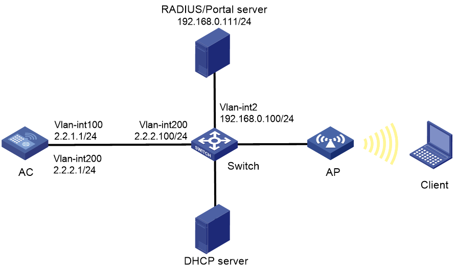
Network configuration
As shown in Figure 1, the AP and the client obtain IP addresses from the DHCP server. The IMC server acts as a portal authentication server, a portal Web server, and a RADIUS server.
Configure the devices to meet the following requirements:
· The AC provides remote MAC authentication and direct portal authentication for the client.
· The RADIUS server can dynamically change user authorization information or forcibly disconnect users.
Analysis
For the client to access network resources through any Layer 2 ports in its access VLAN without re-authentication, enable portal roaming.
For the RADIUS server to dynamically change the user authorization information or forcibly disconnect users, enable the RADIUS session-control feature.
To ensure that dynamic user authorization information can be correctly assigned to users after they come online, enable the RADIUS DAS feature.
Restrictions and guidelines
· Use the serial ID labeled on the AP's rear panel to specify an AP.
· By default, the URL of the portal Web server to which the AC redirects portal users does not carry any parameters. You can add parameters to be carried in the URL as needed.
· If portal authentication is enabled on a VLAN interface, the AC can forward client traffic. If portal authentication is enabled on a service template, both the AC and the AP can forward client traffic. (In this example, portal authentication is enabled on a service template.)
· In wireless networks where the AP forwards client traffic, the AC does not have ARP entries for clients. Therefore, the AC cannot check the validity of portal clients by using ARP entries. To ensure that valid users can perform portal authentication, enable wireless client validity check on the AC.
· If a portal client logs out and then tries to come online frequently in a short time, the client will fail portal authentication. To avoid this problem, disable the Rule ARP entry feature for portal clients.
· Some endpoints by default use random MAC addresses. For transparent MAC authentication to take effect on such an endpoint, disable the endpoint from using a random MAC address.
Procedures
Configuring IMC
This example uses the IMC server to describe the RADIUS server and portal server configuration. The IMC server runs on IMC PLAT 7.1 (E0303p13), IMC EIA 7.1 (F0302p08), and IMC EIP 7.1 (F0302p08).
Configuring the RADIUS server
1. Add the AC to IMC as an access device:
a. Log in to IMC and click the User tab.
b. From the navigation tree, select User Access Policy > Access Device Management > Access Device.
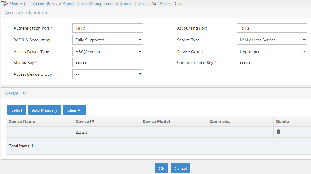
c. Click Add to open the page as shown in Figure 2.
d. In the Access Configuration area, configure the parameters as follows:
- Set the shared key to radius, which must be the same as that on the AC.
- Use the default values for other parameters.
e. In the Device List area, click Add Manually to open the Add Access Device Manually page. Enter 2.2.2.1 in the Start IP field and then click OK.
f. Click OK.
Figure 2 Adding the AC as an access device
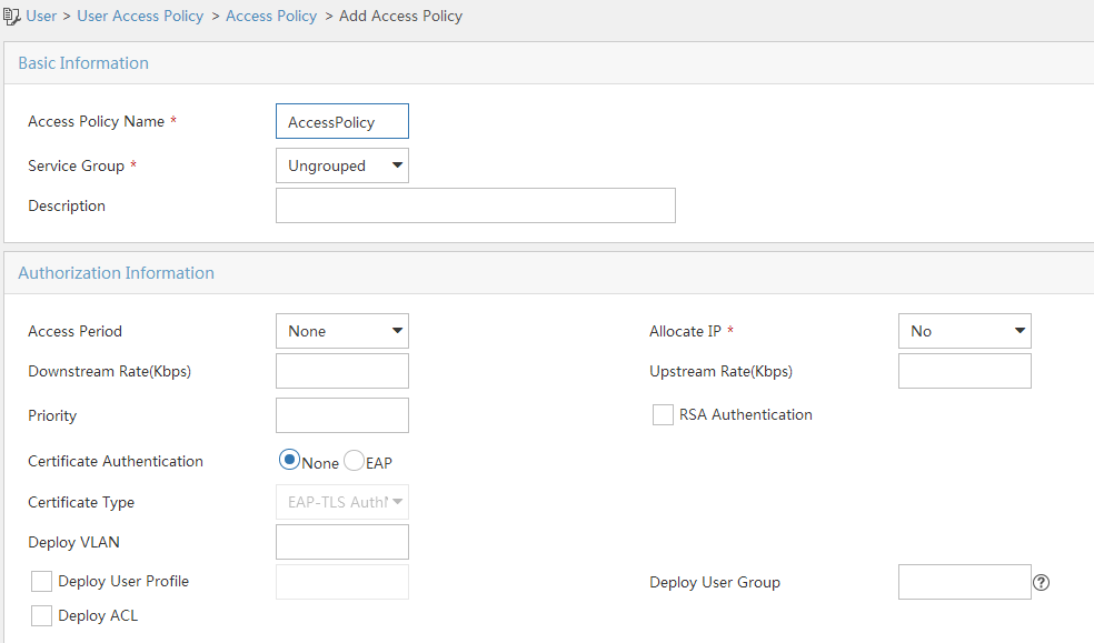
2. Add an access policy:
a. From the navigation tree, select User Access Policy > Access Policy.
b. Click Add to open the page as shown in Figure 3.
c. Enter the access policy name.
d. Select a service group.
This example uses the default value Ungrouped.
e. Use the default settings for other parameters.
f. Click OK.
Figure 3 Adding an access policy
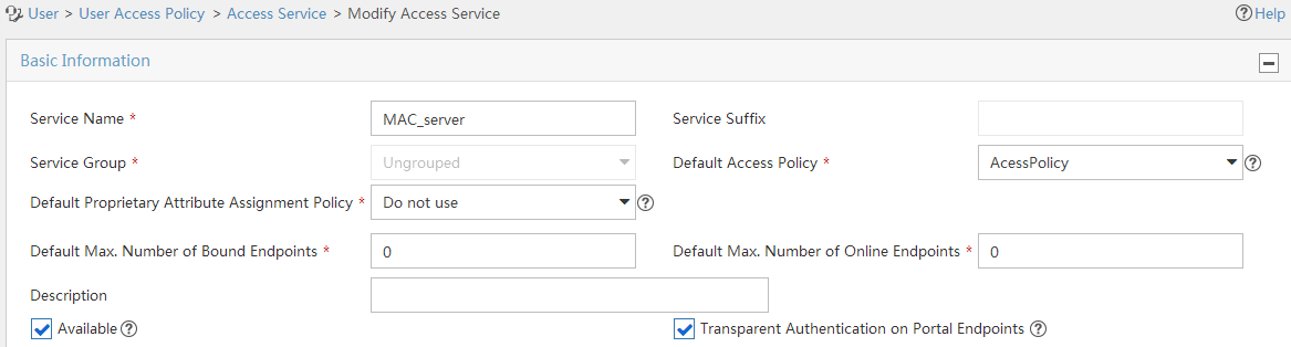
3. Add an access service:
a. From the navigation tree, select User Access Policy > Access Service.
b. Click Add to open the page as shown in Figure 4.
c. Enter the service name.
d. Select the Transparent Authentication on Portal Endpoints option.
e. Use the default settings for other parameters.
f. Click OK.
Figure 4 Adding an access service
4. Add an access user:
a. From the navigation tree, select Access User > Access User.
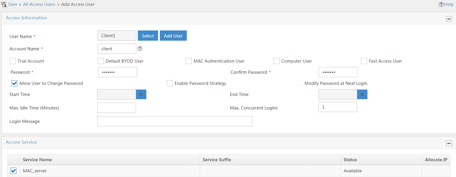
b. Click Add to open the page as shown in Figure 5.
c. Select an existing access user or click Add User to add a new access user.
d. Enter the account name.
e. Set the password.
f. Select the access service.
g. Use the default settings for other parameters.
h. Click OK.
Figure 5 Adding an access user
Configuring the portal server
1. Configure the portal authentication service:
a. Click the User tab.
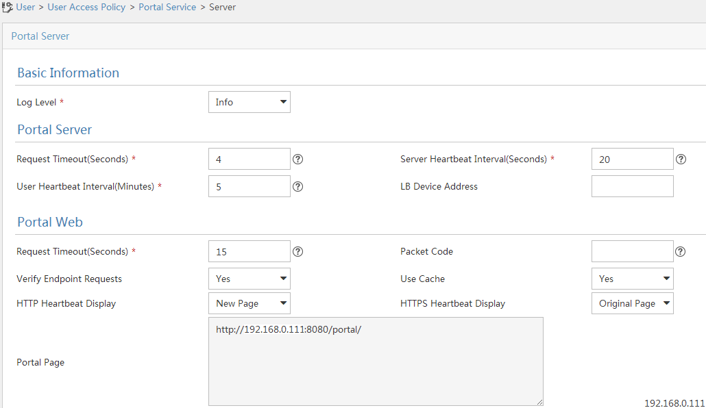
b. From the navigation tree, select User Access Policy > Portal Service > Server to open the portal server configuration page, as shown in Figure 6.
c. Configure the portal server parameters as needed.
This example uses the default values.
d. Click OK.
Figure 6 Portal authentication server configuration
2. Configure an IP address group:
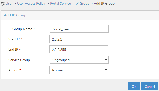
a. From the navigation tree, select User Access Policy > Portal Service > IP Group.
b. Click Add to open the page as shown in Figure 7.
c. Enter the IP group name.
d. Enter the start IP address and end IP address of the IP group.
Make sure the client IP address is in the IP group.
e. Select a service group.
This example uses the default value Ungrouped.
f. From the Action list, select Normal.
g. Click OK.
Figure 7 Adding an IP address group
3. Add a portal device:
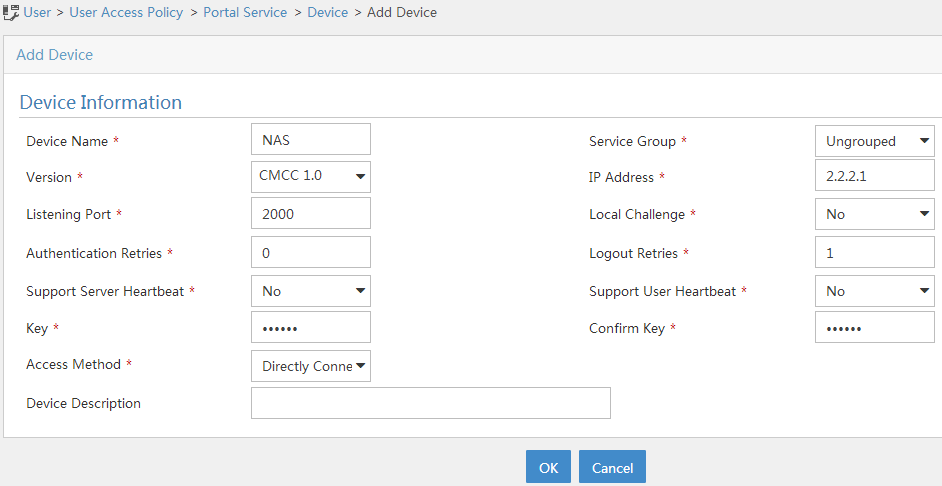
a. From the navigation tree, select User Access Policy > Portal Service > Device.
b. Click Add to open the page as shown in Figure 8.
c. Enter the device name.
d. Select CMCC 1.0 for Version.
e. Enter the IP address of the AC's interface connected to the client.
f. Set whether to support the portal server heartbeat and user heartbeat functions.
In this example, select No for both Support Server Heartbeat and Support User Heartbeat.
g. Enter the key, which must be the same as that configured on the AC.
h. Select Directly Connected for Access Method.
i. Use the default settings for other parameters.
j. Click OK.
Figure 8 Adding a portal device
4. Associate the portal device with the IP address group:
a. As shown in Figure 9,
click the Port Group icon ![]() in the Operation field for device NAS to open the port group
configuration page.
in the Operation field for device NAS to open the port group
configuration page.
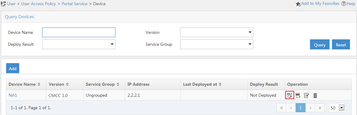
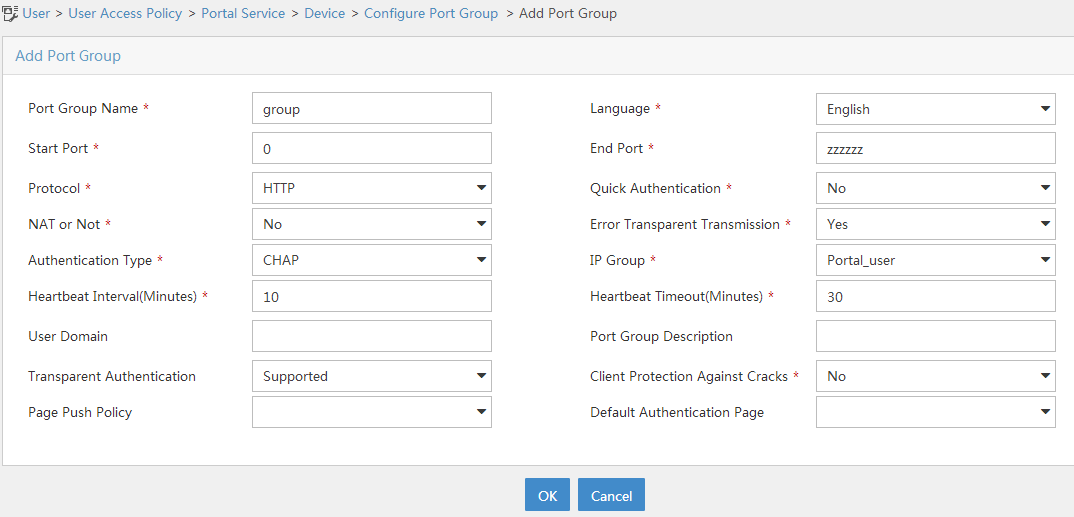
b. Click Add to open the page as shown in Figure 10.
c. Enter the port group name.
d. Select the configured IP address group.
The IP address used by the user to access the network must be within this IP address group.
e. Select Supported for Transparent Authentication.
f. Use the default settings for other parameters.
g. Click OK.
5. From the navigation tree, select User Access Policy > Service Parameters > Validate System Configuration to make the configuration take effect.
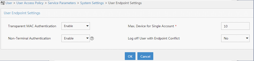
6. Configure system parameters:
a. From the navigation tree, select User Access Policy > Service Parameters > System Settings.
b. Click the Configure
icon ![]() for User Endpoint Settings to open the
page as shown in Figure 11.
for User Endpoint Settings to open the
page as shown in Figure 11.
c. Select Enable for Transparent MAC Authentication.
d. Select whether to enable transparent portal authentication on non-smart devices.
In this example, select Enable for Non-Terminal Authentication.
e. Click OK.
Figure 11 Configuring user endpoint settings
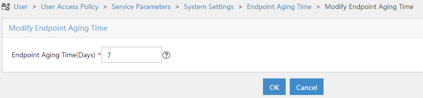
f. Click the Configure
icon ![]() for Endpoint Aging Time to open the page
as shown in Figure 12.
for Endpoint Aging Time to open the page
as shown in Figure 12.
g. Set the endpoint aging time as needed.
This example uses the default value.
h. Click OK.
Figure 12 Setting the endpoint aging time
7. From the navigation tree, select User Access Policy > Service Parameters > Validate System Configuration to make the configuration take effect.
Configuring the AC
1. Configure interfaces on the AC:
# Create VLAN 100 and VLAN-interface 100, and assign an IP address to the VLAN interface. The AC will use this IP address to establish a CAPWAP tunnel with the AP.
<AC> system-view
[AC] vlan 100
[AC-vlan100] quit
[AC] interface vlan-interface 100
[AC-Vlan-interface100] ip address 2.2.1.1 24
[AC-Vlan-interface100] quit
# Create VLAN 200 and VLAN-interface 200, and assign an IP address to the VLAN interface. The AC will use VLAN 200 for client access.
[AC] vlan 200
[AC-vlan200] quit
[AC] interface vlan-interface 200
[AC-Vlan-interface200] ip address 2.2.2.1 24
[AC-Vlan-interface200] quit
# Configure GigabitEthernet 1/0/1 (the port connected to the switch) as a trunk port, and add the trunk port to VLAN 1, VLAN 100, and VLAN 200.
[AC] interface gigabitethernet 1/0/1
[AC-GigabitEthernet1/0/1] port link-type trunk
[AC-GigabitEthernet1/0/1] port trunk permit vlan 1 100 200
[AC-GigabitEthernet1/0/1] quit
2. Configure a static route to the IMC server:
[AC] ip route-static 192.168.0.0 255.255.0.0 2.2.2.100
3. Configure a WLAN service:
# Create a service template named st1 and enter its view.
[AC] wlan service-template st1
# Set the SSID of service template st1 to service.
[AC-wlan-st-st1] ssid service
# Assign clients coming online through service template st1 to VLAN 200.
[AC-wlan-st-st1] vlan 200
[AC-wlan-st-st1] quit
# Create an AP named office with model WA4320i-ACN and set its serial ID to 219801A0CNC138011454.
[AC] wlan ap office model WA4320i-ACN
[AC-wlan-ap-office] serial-id 219801A0CNC138011454
# Enter the view of radio 2.
[AC-wlan-ap-office] radio 2
# Bind service template st1 to radio 2 in AP office.
[AC-wlan-ap-office-radio-2] service-template st1
# Enable radio 2.
[AC-wlan-ap-office-radio-2] radio enable
[AC-wlan-ap-office-radio-2] quit
[AC-wlan-ap-office] quit
4. Configure a RADIUS scheme:
# Create a RADIUS scheme named rs1 and enter its view.
[AC] radius scheme rs1
# Specify the primary authentication server and primary accounting server, and configure the keys for communication with the servers.
[AC-radius-rs1] primary authentication 192.168.0.111
[AC-radius-rs1] primary accounting 192.168.0.111
[AC-radius-rs1] key authentication simple radius
[AC-radius-rs1] key accounting simple radius
# Configure the AC to remove the domain name from the usernames sent to the RADIUS servers.
[AC-radius-rs1] user-name-format without-domain
# Configure the source IP address for outgoing RADIUS packets as 2.2.2.1.
[AC-radius-rs1] nas-ip 2.2.2.1
[AC-radius-rs1] quit
# Enable RADIUS session-control.
[AC] radius session-control enable
# Enable the RADIUS DAS feature and enter RADIUS DAS view.
[AC] radius dynamic-author server
# Specify a session-control client with IP address 192.168.0.111 and shared key radius in plaintext form.
[AC-radius-da-server] client ip 192.168.0.111 key simple radius
[AC-radius-da-server] quit
5. Configure authentication domain dm2:
# Create an ISP domain named dm2 and enter its view.
[AC] domain dm2
# Configure the authentication, authorization, and accounting scheme RADIUS scheme rs1 for LAN access users in the ISP domain.
[AC-isp-dm2] authentication lan-access radius-scheme rs1
[AC-isp-dm2] authorization lan-access radius-scheme rs1
[AC-isp-dm2] accounting lan-access radius-scheme rs1
[AC-isp-dm2] quit
6. Configure authentication domain dm1:
# Create an ISP domain named dm1 and enter its view.
[AC] domain dm1
# Configure the authentication and authorization methods as RADIUS and the accounting method as none for portal users in the ISP domain.
[AC-isp-dm1] authentication portal radius-scheme rs1
[AC-isp-dm1] authorization portal radius-scheme rs1
[AC-isp-dm1] accounting portal none
# Set the idle timeout period to 15 minutes and the minimum traffic that must be generated in the idle timeout period to 1024 bytes.
[AC-isp-dm1] authorization-attribute idle-cut 15 1024
[AC-isp-dm1] quit
7. Configure portal authentication:
# Create a portal authentication server.
[AC] portal server newpt
[AC-portal-server-newpt] ip 192.168.0.111 key simple 123456
[AC-portal-server-newpt] port 50100
# Specify CMCC as the type of portal authentication server newpt.
[AC-portal-server-newpt] server-type cmcc
[AC-portal-server-newpt] quit
# Specify http://192.168.0.111:8080/portal as the URL of portal Web server newpt.
[AC] portal web-server newpt
[AC-portal-websvr-newpt] url http://192.168.0.111:8080/portal
# Configure the portal redirection URL to carry the ssid, wlanuserip, and wlanacname parameters, and their values are the wireless SSID, the user's IP address, and the AC's name (required by a CMCC portal Web server).
[AC-portal-websvr-newpt] url-parameter ssid ssid
[AC-portal-websvr-newpt] url-parameter wlanuserip source-address
[AC-portal-websvr-newpt] url-parameter wlanacname value AC
# Specify CMCC as the type of portal Web server newpt.
[AC-portal-websvr-newpt] server-type cmcc
[AC-portal-websvr-newpt] quit
# Configure a portal-free rule numbered 0 to allow portal users to access the portal Web server (whose IP address is 192.168.0.111) without authentication.
[AC] portal free-rule 0 destination ip 192.168.0.111 24
# Configure a portal-free rule to permit traffic from aggregate interface 1.
[AC] portal free-rule 1 source interface Bridge-Aggregation 1
# Configure destination-based portal-free rules to permit traffic destined for the DNS server.
[AC] portal free-rule 2 destination ip any udp 53
[AC] portal free-rule 3 destination ip any tcp 53
# Enable portal roaming.
[AC] portal roaming enable
# Disable the Rule ARP entry feature for portal clients.
[AC] undo portal refresh arp enable
# Enable validity check on wireless portal clients.
[AC] portal host-check enable
# Enable direct portal authentication on service template st1.
[AC] wlan service-template st1
[AC-wlan-st-st1] portal enable method direct
# Specify ISP domain dm1 as the portal authentication domain.
[AC-wlan-st-st1] portal domain dm1
# Specify portal Web server newpt on service template st1 for portal authentication.
[AC-wlan-st-st1] portal apply web-server newpt
# Configure the source IP address for outgoing portal packets as 2.2.2.1.
[AC-wlan-st-st1] portal bas-ip 2.2.2.1
[AC-wlan-st-st1] quit
8. Configure MAC authentication:
# Set the authentication mode to mac for WLAN clients on service template st1.
[AC-wlan-st-st1] client-security authentication-mode mac
# Configure the AC to ignore MAC authentication failures on service template st1.
[AC-wlan-st-st1] client-security ignore-authentication
# Specify ISP domain dm2 as the authentication domain for MAC authentication clients on service template st1.
[AC-wlan-st-st1] mac-authentication domain dm2
# Enable service template st1.
[AC-wlan-st-st1] service-template enable
[AC-wlan-st-st1] quit
Configuring the switch
# Create VLAN 100. The switch will use this VLAN to forward traffic on the CAPWAP tunnel between the AC and the AP.
<Switch> system-view
[Switch] vlan 100
[Switch-vlan100] quit
# Create VLAN 200. The switch will use this VLAN to forward client traffic.
[Switch] vlan 200
[Switch-vlan200] quit
# Create VLAN 2.
[Switch] vlan 2
[Switch-vlan2] quit
# Configure GigabitEthernet 1/0/1(the port connected to the AC) as a trunk port and assign the port to VLAN 100 and VLAN 200.
[Switch] interface gigabitethernet 1/0/1
[Switch-GigabitEthernet1/0/1] port link-type trunk
[Switch-GigabitEthernet1/0/1] port trunk permit vlan 100 200
[Switch-GigabitEthernet1/0/1] quit
# Configure GigabitEthernet 1/0/2 (the port connected to the AP) as an access port and assign the port to VLAN 100.
[Switch] interface gigabitethernet 1/0/2
[Switch-GigabitEthernet1/0/2] port link-type access
[Switch-GigabitEthernet1/0/2] port access vlan 100
# Enable PoE.
[Switch-GigabitEthernet1/0/2] poe enable
[Switch-GigabitEthernet1/0/2] quit
# Configure GigabitEthernet 1/0/3 (the port connected to the IMC server) as an access port and assign the access port to VLAN 2.
[Switch] interface gigabitethernet 1/0/3
[Switch-GigabitEthernet1/0/3] port link-type access
[Switch-GigabitEthernet1/0/3] port access vlan 2
[Switch-GigabitEthernet1/0/3] quit
# Assign an IP address to VLAN-interface 200.
[Switch] interface vlan-interface 200
[Switch-Vlan-interface200] ip address 2.2.2.100 255.255.255.0
[Switch-Vlan-interface200] quit
# Assign an IP address to VLAN-interface 2.
[Switch] interface vlan-interface 2
[Switch-Vlan-interface2] ip address 192.168.0.100 255.255.255.0
[Switch-Vlan-interface2] quit
Verifying the configuration
1. Verify that the client needs to pass portal authentication when the client attempts to come online for the first time.
In this case, the RADIUS server does not have the user and its MAC address information. The AC determines that the user has failed the MAC authentication and performs portal authentication for the user.
# Display information about all online portal users on the AC.
[AC] display portal user all
Total portal users: 1
Username: client
AP name: office
Radio ID: 2
SSID: service
Portal server: newpt
State: Online
VPN instance: N/A
MAC IP VLAN Interface
0021-6330-0933 2.2.2.2 200 WLAN-BSS1/0/2
Authorization information:
DHCP IP pool: N/A
User profile: N/A
Session group profile: N/A
ACL number: N/A
Inbound CAR: N/A
Outbound CAR: N/A
2. Log out then log in again.
After the client passes portal authentication, the RADIUS server records the user and MAC address information. When the client goes offline and then tries to access the network again, the AC determines that the client has passed MAC authentication and does not perform portal authentication for the client, either.
3. Verify that the client has passed MAC authentication.
# Display information about online MAC authentication users on the AC.
[AC] display mac-authentication connection
User MAC address : 0021-6330-0933
AP name : office
Radio ID : 2
SSID : service
BSSID : 70ba-efaf-ddb0
Username : 002163300933
Authentication domain : dm2
Initial VLAN : 200
Authorization VLAN : 200
Authorization ACL number : N/A
Authorization user profile : N/A
Termination action : Default
Session timeout period : 86401 s
Online from : 2016/04/22 18:56:20
Configuration files
· AC:
#
vlan 100
#
vlan 200
#
wlan service-template st1
ssid service
vlan 200
client-security authentication-mode mac
client-security ignore-authentication
mac-authentication domain dm2
portal enable method direct
portal domain dm1
portal bas-ip 2.2.2.1
portal apply web-server newpt
portal apply mac-trigger-server mts
service-template enable
#
interface Vlan-interface100
ip address 2.2.1.1 255.255.255.0
#
interface Vlan-interface200
ip address 2.2.2.1 255.255.255.0
#
interface GigabitEthernet1/0/1
port link-mode bridge
port link-type trunk
port trunk permit vlan 1 100 200
#
ip route-static 192.168.0.0 16 2.2.2.100
#
radius session-control enable
#
radius scheme rs1
primary authentication 192.168.0.111
primary accounting 192.168.0.111
key authentication cipher $c$3$Sqgqz7lDs4XPnethmAgyAKVlke7qwEkYbQ==
key accounting cipher $c$3$4J/JBRGwqB4F213furJMkB6JWYXBFjWE6g==
user-name-format without-domain
nas-ip 2.2.2.1
#
radius dynamic-author server
client ip 192.168.0.111 key cipher $c$3$AkTEB7OgMYnCqsfDeplhoAgXUek/rVrLZw==
#
domain dm1
authorization-attribute idle-cut 15 1024
authentication portal radius-scheme rs1
authorization portal radius-scheme rs1
accounting portal none
#
domain dm2
authorization-attribute idle-cut 15 1024
authentication lan-access radius-scheme rs1
authorization lan-access radius-scheme rs1
accounting lan-access radius-scheme rs1
#
portal host-check enable
portal free-rule 0 destination ip 192.168.0.0 255.255.255.0
portal free-rule 1 source interface Bridge-Aggregation 1
portal free-rule 2 destination ip any udp 53
portal free-rule 3 destination ip any tcp 53
#
portal roaming enable
undo portal refresh arp enable
#
portal web-server newpt
url http://192.168.0.111:8080/portal
server-type cmcc
url-parameter ssid ssid
url-parameter wlanacname value AC
url-parameter wlanuserip source-address
#
portal server newpt
ip 192.168.0.111 key cipher $c$3$jiLQ5VIGG4TF7R3sHTT07bmv9rtiSQYBzQ==
server-type cmcc
#
wlan ap office model WA4320i-ACN
serial-id 219801A0CNC138011454
radio 1
radio 2
radio enable
service-template st1
#
· Switch:
#
vlan 2
#
vlan 100
#
vlan 200
#
interface Vlan-interface2
ip address 192.168.0.100 255.255.255.0
#
interface Vlan-interface200
ip address 2.2.2.100 255.255.255.0
#
interface GigabitEthernet1/0/1
port link-type trunk
port trunk permit vlan 1 100 200
#
interface GigabitEthernet1/0/2
port link-type access
port access vlan 100
poe enable
#
interface GigabitEthernet1/0/3
port link-type access
port access vlan 2
#
Related documentation
· AP and WT Management Command Reference in H3C Access Controllers Command References
· AP and WT Management Configuration Guide in H3C Access Controllers Configuration Guides
· User Access and Authentication Command Reference in H3C Access Controllers Command References
· User Access and Authentication Configuration Guide in H3C Access Controllers Configuration Guides
· WLAN Access Command Reference in H3C Access Controllers Command References
· WLAN Access Configuration Guide in H3C Access Controllers Configuration Guides
