- Table of Contents
-
- 03-CLI configuration examples (AC+fit AP)
- 01-HTTPS Login Configuration Examples
- 02-SSH Configuration Examples
- 03-License Management Configuration Examples
- 04-IPv6 URL Redirection Configuration Examples
- 05-AP Association with the AC at Layer 2 Configuration Examples
- 06-AP Association with the AC at Layer 2 (IPv6) Configuration Examples
- 07-Auto AP Configuration Examples
- 08-AP Association with the AC at Layer 3 Configuration Examples
- 09-AP Association with the AC at Layer 3 (IPv6) Configuration Examples
- 10-WEP Encryption Configuration Examples
- 11-PSK Encryption Configuration Examples
- 12-WPA3-SAE PSK Encryption Configuration Examples
- 13-WLAN Access (IPv6) Configuration Examples
- 14-Policy-Based Forwarding with Dual Gateways Configuration Examples
- 15-Scheduled Configuration Deployment by AP Group Configuration Examples
- 16-Inter-AC Roaming with Static Client VLAN Allocation Configuration Examples
- 17-Service Template and Radio Binding Configuration Examples
- 18-Scheduled WLAN Access Services Configuration Examples
- 19-Local Portal Authentication Configuration Examples
- 20-HTTPS-Based Local Portal Authentication Configuration Examples
- 21-Remote Portal Authentication Configuration Examples
- 22-Local Portal Authentication through LDAP Server Configuration Examples
- 23-Local Portal Authentication and SSID-based Authentication Page Pushing Configuration Examples
- 24-Local Portal MAC-Trigger Authentication Configuration Examples
- 25-Portal MAC-Trigger Authentication Configuration Examples
- 26-Local Forwarding Mode and Local Portal MAC-Trigger Authentication Configuration Examples
- 27-Local Portal Authentication (IPv6) Configuration Examples
- 28-Local Portal Authentication through LDAP Server (IPv6) Configuration Examples
- 29-Remote Portal Authentication (IPv6) Configuration Examples
- 30-Portal MAC-Trigger Authentication (IPv6) Configuration Example
- 31-Remote Portal Authentication with User Profile Authorization Configuration Examples
- 32-Portal Fail-Permit Configuration Examples
- 33-Local MAC Authentication Configuration Examples
- 34-MAC Authentication and PSK Authentication Configuration Examples
- 35-Remote MAC and Portal Authentication and Transparent Authentication Configuration Examples
- 36-Remote AP and Remote Portal MAC-Trigger Authentication Configuration Examples
- 37-MAC Authentication with Guest VLAN Assignment Configuration Examples
- 38-MAC Authentication with Guest VLAN Assignment (IPv6) Configuration Examples
- 39-Local MAC-Then-802.1X Authentication Configuration Examples
- 40-Local 802.1X Authentication Configuration Examples
- 41-Local RADIUS-Based 802.1X Authentication in EAP Relay Mode Configuration Examples
- 42-Remote 802.1X Authentication Configuration Examples
- 43-Remote 802.1X Authentication (IPv6) Configuration Examples
- 44-Remote 802.1X Authentication in WPA3-Enterprise Mode Configuration Examples
- 45-802.1X Authentication with ACL Assignment Through IMC Server Configuration Examples
- 46-802.1X Authentication with User Profile Assignment Through IMC Server Configuration Examples
- 47-EAD Authentication Configuration Examples
- 48-EAD Authentication (IPv6) Configuration Examples
- 49-Local Forwarding Mode and Local Portal Authentication Configuration Examples
- 50-Local Forwarding Mode Direct Portal Authentication Configuration Examples
- 51-Local Forwarding Mode Direct Portal Authentication (IPv6) Configuration Examples
- 52-Local Forwarding Configuration Examples
- 53-Remote AP Configuration Examples
- 54-WIPS Configuration Examples
- 55-WIPS Countermeasures Against All SSIDs Configuration Examples
- 56-IP Source Guard (IPv4) Configuration Examples
- 57-IP Source Guard (IPv6) Configuration Examples
- 58-IRF Setup with Members Directly Connected Configuration Examples
- 59-IRF Setup with Members Not Directly Connected Configuration Examples
- 60-IRF Setup with Members in One Chassis Configuration Examples
- 61-IRF Setup with Members in Different Chassis Configuration Examples
- 62-Dual-Link Backup Configuration Examples
- 63-Remote 802.1X Auth on AC Hierarchy Network with Dual-Link Central AC Backup Configuration Examples
- 64-Remote Portal Auth on AC Hierarchy Network with Dual-Link Central AC Backup Configuration Examples
- 65-OAuth-Based Portal MAC-Trigger Auth on Local-Forwarding Dual-Link Backup Configuration Examples
- 66-Dual-Link Backup OAuth-Based Portal Auth in Local Forwarding Configuration Examples
- 67-Dual-Link Backup Remote Portal MAC-Trigger Auth in Local Forwarding Configuration Examples
- 68-Dual-Link Backup Remote Portal and Transparent MAC Auth in Local Forwarding Configuration Examples
- 69-Dual-Link Backup Remote Portal Auth in Local Forwarding Configuration Examples
- 70-Dual-Link Backup Remote Portal and MAC Auth in Centralized Forward Configuration Examples
- 71-Dual-Link Backup Remote Portal Auth in Centralized Forwarding Configuration Examples
- 72-Dual-Link Backup Lightweight Portal Auth in Centralized Forwarding Configuration Examples
- 73-Dual-Link Backup OAuth-Based Portal Auth in Centralized Forwarding Configuration Examples
- 74-Dual-Link Backup Remote Portal MAC-Trigger Auth in Centralized Forwarding Configuration Examples
- 75-Remote 802.1X Auth on a Dual-Link AC Backup Network Configuration Examples
- 76-Remote MAC Auth on a Dual-Link AC Backup Network Configuration Examples
- 77-Remote 802.1X Authentication on an AC Hierarchy Network Configuration Examples
- 78-Remote 802.1X Authentication Configuration Examples
- 79-WLAN Probe Configuration Examples
- 80-Multicast Optimization Configuration Examples
- 81-Client Rate Limiting Configuration Examples
- 82-Inter-AC Roaming Configuration Examples
- 83-Inter-AC Roaming (IPv6) Configuration Examples
- 84-WLAN Load Balancing Configuration Examples
- 85-Static Blacklist Configuration Examples
- 86-Client Quantity Control Configuration Examples
- 87-AP License Synchronization Configuration Examples
- 88-iBeacon Management Configuration Examples
- 89-Mesh Link Establishment Between a Fit AP and a Fat AP Configuration Examples
- 90-Mesh Link Establishment Between Fit APs Configuration Examples
- 91-Auto-DFS and Auto-TPC Configuration Examples
- 92-AP Image Downloading Configuration Examples
- 93-Dual-Uplink Interfaces Configuration Guide
- 94-Internal-to-External Access Through NAT Configuration Examples
- 95-Layer 2 Static Aggregation Configuration Examples
- 96-Layer 2 Multicast Configuration Examples
- 97-Static VLAN Allocation Configuration Examples
- 98-URL Redirection Configuration Examples
- Related Documents
-
| Title | Size | Download |
|---|---|---|
| 34-MAC Authentication and PSK Authentication Configuration Examples | 372.66 KB |
|
|
|
H3C Access Controllers |
|
Comware 7 MAC Authentication and PSK Authentication |
|
Configuration Examples |
Copyright © 2022 New H3C Technologies Co., Ltd. All rights reserved.
No part of this manual may be reproduced or transmitted in any form or by any means without prior written consent of New H3C Technologies Co., Ltd.
Except for the trademarks of New H3C Technologies Co., Ltd., any trademarks that may be mentioned in this document are the property of their respective owners.
The information in this document is subject to change without notice.
Introduction
The following information provides an example for configuring PSK authentication and MAC authentication.
Prerequisites
The following information applies to Comware 7-based access controllers and access points. Procedures and information in the examples might be slightly different depending on the software or hardware version of the access controllers and access points.
The configuration examples were created and verified in a lab environment, and all the devices were started with the factory default configuration. When you are working on a live network, make sure you understand the potential impact of every command on your network.
The following information is provided based on the assumption that you have basic knowledge of AAA, MAC authentication, WLAN authentication, and WLAN access.
Example: Configuring MAC authentication and PSK authentication
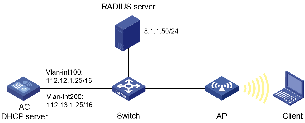
Network configuration
As shown in Figure 1, the AC acts as a DHCP server to provide IP addresses for the AP and the client. The AC centrally forwards the client traffic.
To control the client's access to network resources, complete the following tasks:
· Configure VLAN 200 as the access VLAN of the client.
· Configure the AC to use the RADIUS server to perform MAC authentication for the client.
· Set the AKM mode to PSK to secure data transmission between the client and the AP.
Restrictions and guidelines
When you configure MAC authentication with the PSK AKM mode for wireless clients, follow these restrictions and guidelines:
· On the AC, specify the user account format for MAC authentication. In this example, the MAC address of the client is used as the username and password. Make sure the username and password configuration on the RADIUS server are consistent with the configuration on the AC.
· Use the serial ID labeled on the AP's rear panel to specify an AP.
· Remove the ports that connect the AC to the AP from VLAN 1 in case there are too many packets in VLAN 1.
· Some endpoints by default use random MAC addresses. To ensure successful MAC authentication for such an endpoint, disable the endpoint from using a random MAC address.
Procedures
Configuring the AC
1. Configure interfaces on the AC:
# Create VLAN 100 and VLAN-interface 100, and assign an IP address to the VLAN interface. The AC will use this IP address to establish CAPWAP tunnels with the AP.
<AC> system-view
[AC] vlan 100
[AC-vlan100] quit
[AC] interface vlan-interface 100
[AC-Vlan-interface100] ip address 112.12.1.25 16
[AC-Vlan-interface100] quit
# Create VLAN 200 and VLAN-interface 200, and assign an IP address to the VLAN interface. VLAN 200 will be used for client access.
[AC] vlan 200
[AC-vlan200] quit
[AC] interface vlan-interface 200
[AC-Vlan-interface200] ip address 112.13.1.25 16
[AC-Vlan-interface200] quit
# Configure GigabitEthernet 1/0/1 (the port connected to the switch) as a trunk port, remove the port from VLAN 1, and assign the port to VLANs 100 and 200.
[AC] interface gigabitethernet 1/0/1
[AC-GigabitEthernet1/0/1] port link-type trunk
[AC-GigabitEthernet1/0/1] undo port trunk permit vlan 1
[AC-GigabitEthernet1/0/1] port trunk permit vlan 100 200
# Set the PVID of GigabitEthernet 1/0/1 to VLAN 100.
[AC-GigabitEthernet1/0/1] port trunk pvid vlan 100
[AC-GigabitEthernet1/0/1] quit
2. Configure DHCP:
# Enable DHCP.
[AC] dhcp enable
# Create a DHCP address pool named vlan100, and specify subnet 112.12.0.0/16 and gateway IP address 112.12.1.25 in the DHCP address pool.
[AC] dhcp server ip-pool vlan100
[AC-dhcp-pool-vlan100] network 112.12.0.0 mask 255.255.0.0
[AC-dhcp-pool-vlan100] gateway-list 112.12.1.25
[AC-dhcp-pool-vlan100] quit
# Create a DHCP address pool named vlan200, and specify subnet 112.13.0.0/16 and gateway IP address 112.13.1.25 in the DHCP address pool. In this example, the address of the DNS server is 112.13.1.30 (the gateway address). You must replace it with the actual address of the DNS server on your network.
[AC] dhcp server ip-pool vlan200
[AC-dhcp-pool-vlan200] network 112.13.0.0 mask 255.255.0.0
[AC-dhcp-pool-vlan200] gateway-list 112.13.1.30
[AC-dhcp-pool-vlan200] dns-list 112.13.1.30
[AC-dhcp-pool-vlan200] quit
3. Configure RADIUS-based MAC authentication:
# Create a RADIUS scheme named office and enter its view.
[AC] radius scheme office
# Specify the IP addresses of the primary authentication and accounting RADIUS servers.
[AC-radius-office] primary authentication 8.1.1.50
[AC-radius-office] primary accounting 8.1.1.50
# Specify the shared keys for RADIUS authentication and accounting.
[AC-radius-office] key authentication simple 123456789
[AC-radius-office] key accounting simple 123456789
# Exclude the ISP domain names from the usernames sent to the RADIUS servers.
[AC-radius-office] user-name-format without-domain
# Specify IP address 112.12.1.25 as the source IP address for outgoing RADIUS packets.
[AC-radius-office] nas-ip 112.12.1.25
[AC-radius-office] quit
# Create an ISP domain named office1 and enter its view.
[AC] domain office1
# Apply RADIUS scheme office to ISP domain office1 for LAN user authentication, authorization, and accounting.
[AC-isp-office1] authentication lan-access radius-scheme office
[AC-isp-office1] authorization lan-access radius-scheme office
[AC-isp-office1] accounting lan-access radius-scheme office
# Configure the idle cut feature for clients in ISP domain office1.
[AC-isp-office1] authorization-attribute idle-cut 15 1024
[AC-isp-office1] quit
# Configure the AC to use the MAC address of each user as both the username and password for MAC authentication. The MAC addresses are in hexadecimal notation without hyphens and with letters in lower case. (The configuration in this step is the default configuration. This step is optional.)
[AC] mac-authentication user-name-format mac-address without-hyphen lowercase
4. Configure a wireless service:
# Create a service template named 1 and enter its view.
[AC] wlan service-template 1
# Configure the SSID of service template 1 as service.
[AC-wlan-st-1] ssid service
# Assign clients coming online through the service template to VLAN 200.
[AC-wlan-st-1] vlan 200
# Set the authentication mode to MAC authentication.
[AC-wlan-st-1] client-security authentication-mode mac
# Specify ISP domain office1 as the MAC authentication domain.
[AC-wlan-st-1] mac-authentication domain office1
5. Configure the AKM mode for the service template:
# Set the AKM mode to PSK.
[AC-wlan-st-1] akm mode psk
# Configure the plaintext string of 123456789 as the PSK.
[AC-wlan-st-1] preshared-key pass-phrase simple 123456789
# Configure CCMP as the cipher suite and enable the RSN IE in beacon and probe responses.
[AC-wlan-st-1] cipher-suite ccmp
[AC-wlan-st-1] security-ie rsn
# Enable the service template.
[AC-wlan-st-1] service-template enable
[AC-wlan-st-1] quit
6. Configure manual AP officeap, and bind service template 1 to an AP radio:
# Create a manual AP named officeap, and specify the AP model and serial ID.
[AC] wlan ap officeap model WA4320i-ACN
[AC-wlan-ap-officeap] serial-id 210235A1Q2C159000021
# Enter the view of radio 2, and bind service template 1 to radio 2.
[AC-wlan-ap-officeap] radio 2
[AC-wlan-ap-officeap-radio-2] service-template 1
# Enable radio 2.
[AC-wlan-ap-officeap-radio-2] radio enable
[AC-wlan-ap-officeap-radio-2] quit
[AC-wlan-ap-officeap] quit
Configuring the switch
# Create VLAN 100. The switch will use this VLAN to forward the traffic on the CAPWAP tunnels between the AC and AP.
<Switch> system-view
[Switch] vlan 100
[Switch-vlan100] quit
# Create VLAN 200. The switch will use this VLAN to forward packets for wireless clients.
[Switch] vlan 200
[Switch-vlan200] quit
# Configure GigabitEthernet 1/0/1 (the port connected to the AC) as a trunk port, remove the port from VLAN 1, and assign the trunk port to VLAN 100.
[Switch] interface gigabitethernet 1/0/1
[Switch-GigabitEthernet1/0/1] port link-type trunk
[Switch-GigabitEthernet1/0/1] undo port trunk permit vlan 1
[Switch-GigabitEthernet1/0/1] port trunk permit vlan 100
# Set the PVID of GigabitEthernet 1/0/1 to VLAN 100.
[Switch-GigabitEthernet1/0/1] port trunk pvid vlan 100
[Switch-GigabitEthernet1/0/1] quit
# Configure GigabitEthernet 1/0/2 1 (the port connected to the AP) as an access port. Assign the access port to VLAN 100.
[Switch] interface gigabitethernet 1/0/2
[Switch-GigabitEthernet1/0/2] port link-type access
[Switch-GigabitEthernet1/0/2] port access vlan 100
# Enable PoE on GigabitEthernet 1/0/2.
[Switch-GigabitEthernet1/0/2] poe enable
[Switch-GigabitEthernet1/0/2] quit
Configuring the RADIUS server
In this example, the RADIUS server runs IMC PLAT 7.1(E0303P10) and IMC UAM 7.1(E0303P10).
1. Add an access device:
a. Log in to IMC and click the User tab.
b. From the navigation tree, select User Access Policy > Access Device Management > Access Device.
c. Click Add.
The Add Access Device page opens.
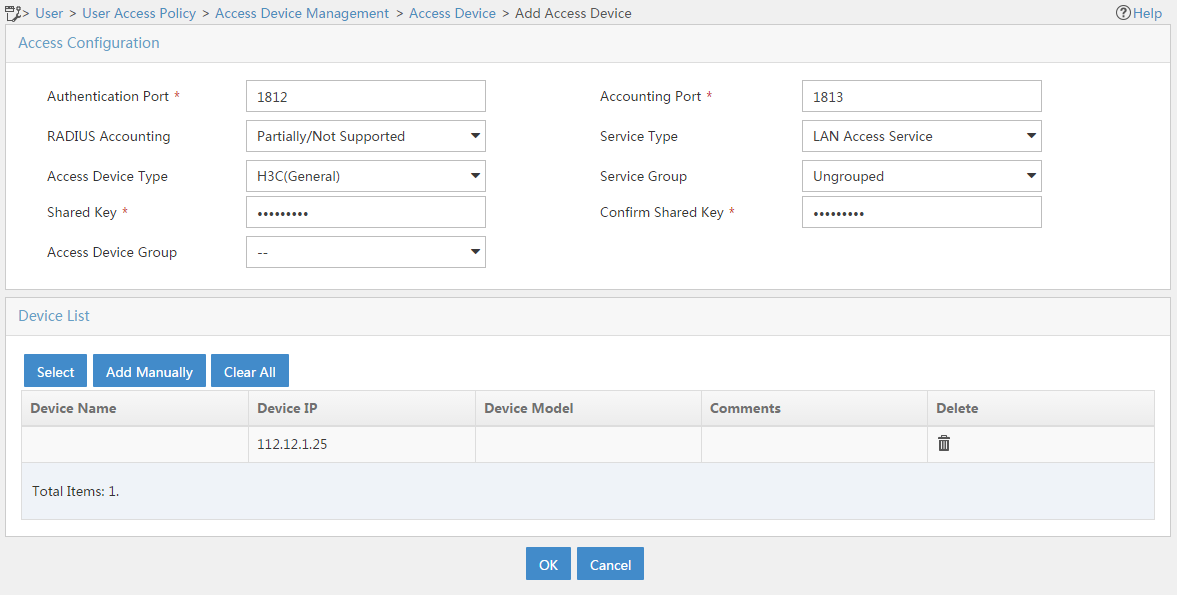
d. In the Device List area, click Add Manually to add the device at 112.12.1.25 as an access device.
This IP address is the source IP address specified on the AC for outgoing RADIUS packets.
e. In the Access Configuration area, configure the following parameters, as shown in Figure 2:
- Enter 123456789 in the Shared Key and Confirm Shared Key fields.
The key is consistent with the shared key configured on the AC.
- Use the default values for other parameters.
f. Click OK.
Figure 2 Adding an access device
2. Add an access policy:
a. Click the User tab.
b. From the navigation tree, select User Access Policy > Access Policy.
c. Click Add.
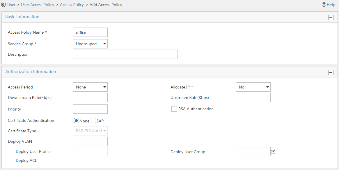
d. On the Add Access Policy page, configure the following parameters, as shown in Figure 3:
- Enter office in the Access Policy Name field.
- Use the default values for other parameters.
Figure 3 Adding an access policy
3. Add an access service:
a. Click the User tab.
b. From the navigation tree, select User Access Policy > Access Service.
c. Click Add.
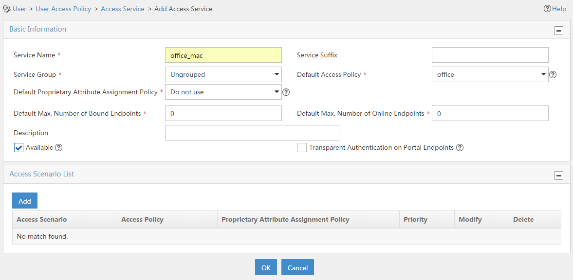
d. On the Add Access Service page, configure the following parameters, as shown in Figure 4:
- Enter office_mac in the Service Name field.
- Select office from the Default Access Policy list.
- Use the default values for other parameters.
e. Click OK.
Figure 4 Adding an access service
4. Add an access user:
a. Click the User tab.
b. From the navigation tree, select Access User > Access User.
The access user list opens.
c. Click Add.
The Add Access User page opens.
d. In the Access Information area, add a user, as shown in Figure 5:
- Click Add User.
- On the dialog box that opens, enter adm_office_mac in the User Name and Identity Number fields.
- Click Check Availability to verify the validity of the username and identity number.
- Click OK.
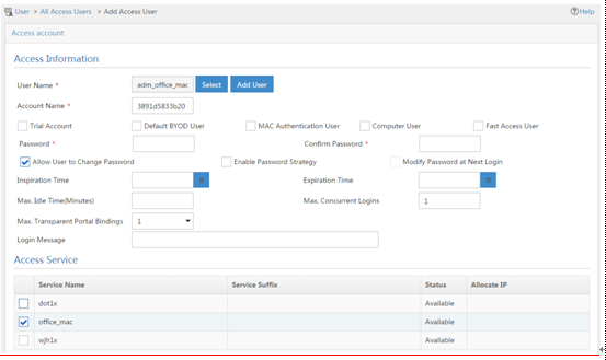
e. In the Access Information area, configure the following parameters, as shown in Figure 6:
- Enter 3891d5833b20 in the Account Name field.
- Enter 3891d5833b20 in the Password and Confirm Password fields.
f. In the Access Service area, select office_mac from the list.
g. Click OK.
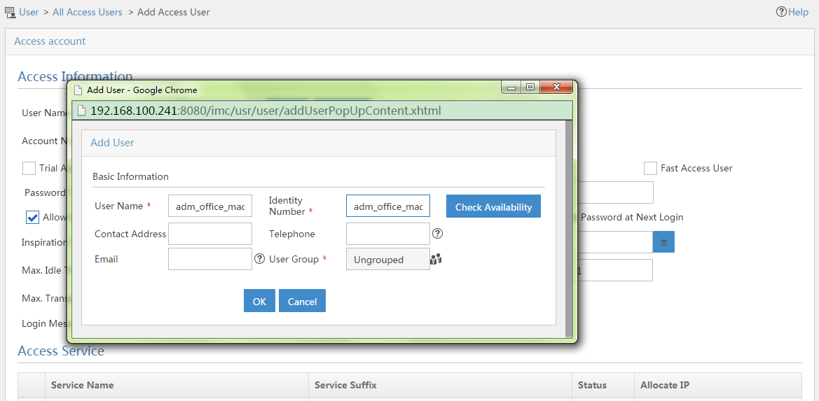
Figure 6 Adding an access user account
Verifying the configuration
The client requests to access the network.
# On the AC, verify that the wireless client has passed MAC authentication and PSK authentication and come online on VLAN 200.
[AC] display wlan client
Total Number of Clients : 1
MAC address Username AP name RID IP address IPv6 address VLAN
3891-d583-3b20 3891d5833b20 officeap 2 112.13.0.2 N/A 200
Configuration files
· AC:
#
dhcp enable
#
vlan 1
#
vlan 100
#
vlan 200
#
dhcp server ip-pool vlan100
gateway-list 112.12.1.25
network 112.12.0.0 mask 255.255.0.0
#
dhcp server ip-pool vlan200
gateway-list 112.13.1.30
network 112.13.0.0 mask 255.255.0.0
dns-list 112.13.1.30
#
wlan service-template 1
ssid service
vlan 200
akm mode psk
preshared-key pass-phrase cipher $c$3$heDUT35pq2/Zmsuy18nxS3vSHAeolC6kobTrDA==
cipher-suite ccmp
security-ie rsn
client-security authentication-mode mac
mac-authentication domain office1
service-template enable
#
interface Vlan-interface100
ip address 112.12.1.25 255.255.0.0
#
interface Vlan-interface200
ip address 112.13.1.25 255.255.0.0
#
interface GigabitEthernet1/0/1
port link-type trunk
undo port trunk permit vlan 1
port trunk permit vlan 100 200
port trunk pvid vlan 100
#
radius scheme office
primary authentication 8.1.1.50
primary accounting 8.1.1.50
key authentication cipher $c$3$o/3Ueu4pLSdJ0r1kLdAwzJU/AaBGCxnGuBXHmQ==
key accounting cipher $c$3$oKqS/GRbPQc8AG+Vp+bJO4ZPKlk5+ceFuye/tQ==
user-name-format without-domain
nas-ip 112.12.1.25
#
domain office1
authorization-attribute idle-cut 15 1024
authentication lan-access radius-scheme office
authorization lan-access radius-scheme office
accounting lan-access radius-scheme office
#
wlan ap officeap model WA4320i-ACN
serial-id 210235A1Q2C159000021
vlan 1
radio 1
radio 2
radio enable
service-template 1
#
· Switch:
#
vlan 1
#
vlan 100
#
vlan 200
#
interface GigabitEthernet1/0/1
port link-type trunk
undo port trunk permit vlan 1
port trunk permit vlan 100
port trunk pvid vlan 100
#
interface GigabitEthernet1/0/2
port access vlan 100
poe enable
#
Related documentation
· AP and WT Management Configuration Guide in H3C Access Controllers Configuration Guides
· AP and WT Management Command Reference in H3C Access Controllers Command References
· Network Connectivity Configuration Guide in H3C Access Controllers Configuration Guides
· Network Connectivity Command Reference in H3C Access Controllers Command References
· User Access and Authentication Configuration Guide in H3C Access Controllers Configuration Guides
· User Access and Authentication Command Reference in H3C Access Controllers Command References
· WLAN Access Configuration Guide in H3C Access Controllers Configuration Guides
· WLAN Access Command Reference in H3C Access Controllers Command References
