- Table of Contents
-
- 03-CLI configuration examples (AC+fit AP)
- 01-HTTPS Login Configuration Examples
- 02-SSH Configuration Examples
- 03-License Management Configuration Examples
- 04-IPv6 URL Redirection Configuration Examples
- 05-AP Association with the AC at Layer 2 Configuration Examples
- 06-AP Association with the AC at Layer 2 (IPv6) Configuration Examples
- 07-Auto AP Configuration Examples
- 08-AP Association with the AC at Layer 3 Configuration Examples
- 09-AP Association with the AC at Layer 3 (IPv6) Configuration Examples
- 10-WEP Encryption Configuration Examples
- 11-PSK Encryption Configuration Examples
- 12-WPA3-SAE PSK Encryption Configuration Examples
- 13-WLAN Access (IPv6) Configuration Examples
- 14-Policy-Based Forwarding with Dual Gateways Configuration Examples
- 15-Scheduled Configuration Deployment by AP Group Configuration Examples
- 16-Inter-AC Roaming with Static Client VLAN Allocation Configuration Examples
- 17-Service Template and Radio Binding Configuration Examples
- 18-Scheduled WLAN Access Services Configuration Examples
- 19-Local Portal Authentication Configuration Examples
- 20-HTTPS-Based Local Portal Authentication Configuration Examples
- 21-Remote Portal Authentication Configuration Examples
- 22-Local Portal Authentication through LDAP Server Configuration Examples
- 23-Local Portal Authentication and SSID-based Authentication Page Pushing Configuration Examples
- 24-Local Portal MAC-Trigger Authentication Configuration Examples
- 25-Portal MAC-Trigger Authentication Configuration Examples
- 26-Local Forwarding Mode and Local Portal MAC-Trigger Authentication Configuration Examples
- 27-Local Portal Authentication (IPv6) Configuration Examples
- 28-Local Portal Authentication through LDAP Server (IPv6) Configuration Examples
- 29-Remote Portal Authentication (IPv6) Configuration Examples
- 30-Portal MAC-Trigger Authentication (IPv6) Configuration Example
- 31-Remote Portal Authentication with User Profile Authorization Configuration Examples
- 32-Portal Fail-Permit Configuration Examples
- 33-Local MAC Authentication Configuration Examples
- 34-MAC Authentication and PSK Authentication Configuration Examples
- 35-Remote MAC and Portal Authentication and Transparent Authentication Configuration Examples
- 36-Remote AP and Remote Portal MAC-Trigger Authentication Configuration Examples
- 37-MAC Authentication with Guest VLAN Assignment Configuration Examples
- 38-MAC Authentication with Guest VLAN Assignment (IPv6) Configuration Examples
- 39-Local MAC-Then-802.1X Authentication Configuration Examples
- 40-Local 802.1X Authentication Configuration Examples
- 41-Local RADIUS-Based 802.1X Authentication in EAP Relay Mode Configuration Examples
- 42-Remote 802.1X Authentication Configuration Examples
- 43-Remote 802.1X Authentication (IPv6) Configuration Examples
- 44-Remote 802.1X Authentication in WPA3-Enterprise Mode Configuration Examples
- 45-802.1X Authentication with ACL Assignment Through IMC Server Configuration Examples
- 46-802.1X Authentication with User Profile Assignment Through IMC Server Configuration Examples
- 47-EAD Authentication Configuration Examples
- 48-EAD Authentication (IPv6) Configuration Examples
- 49-Local Forwarding Mode and Local Portal Authentication Configuration Examples
- 50-Local Forwarding Mode Direct Portal Authentication Configuration Examples
- 51-Local Forwarding Mode Direct Portal Authentication (IPv6) Configuration Examples
- 52-Local Forwarding Configuration Examples
- 53-Remote AP Configuration Examples
- 54-WIPS Configuration Examples
- 55-WIPS Countermeasures Against All SSIDs Configuration Examples
- 56-IP Source Guard (IPv4) Configuration Examples
- 57-IP Source Guard (IPv6) Configuration Examples
- 58-IRF Setup with Members Directly Connected Configuration Examples
- 59-IRF Setup with Members Not Directly Connected Configuration Examples
- 60-IRF Setup with Members in One Chassis Configuration Examples
- 61-IRF Setup with Members in Different Chassis Configuration Examples
- 62-Dual-Link Backup Configuration Examples
- 63-Remote 802.1X Auth on AC Hierarchy Network with Dual-Link Central AC Backup Configuration Examples
- 64-Remote Portal Auth on AC Hierarchy Network with Dual-Link Central AC Backup Configuration Examples
- 65-OAuth-Based Portal MAC-Trigger Auth on Local-Forwarding Dual-Link Backup Configuration Examples
- 66-Dual-Link Backup OAuth-Based Portal Auth in Local Forwarding Configuration Examples
- 67-Dual-Link Backup Remote Portal MAC-Trigger Auth in Local Forwarding Configuration Examples
- 68-Dual-Link Backup Remote Portal and Transparent MAC Auth in Local Forwarding Configuration Examples
- 69-Dual-Link Backup Remote Portal Auth in Local Forwarding Configuration Examples
- 70-Dual-Link Backup Remote Portal and MAC Auth in Centralized Forward Configuration Examples
- 71-Dual-Link Backup Remote Portal Auth in Centralized Forwarding Configuration Examples
- 72-Dual-Link Backup Lightweight Portal Auth in Centralized Forwarding Configuration Examples
- 73-Dual-Link Backup OAuth-Based Portal Auth in Centralized Forwarding Configuration Examples
- 74-Dual-Link Backup Remote Portal MAC-Trigger Auth in Centralized Forwarding Configuration Examples
- 75-Remote 802.1X Auth on a Dual-Link AC Backup Network Configuration Examples
- 76-Remote MAC Auth on a Dual-Link AC Backup Network Configuration Examples
- 77-Remote 802.1X Authentication on an AC Hierarchy Network Configuration Examples
- 78-Remote 802.1X Authentication Configuration Examples
- 79-WLAN Probe Configuration Examples
- 80-Multicast Optimization Configuration Examples
- 81-Client Rate Limiting Configuration Examples
- 82-Inter-AC Roaming Configuration Examples
- 83-Inter-AC Roaming (IPv6) Configuration Examples
- 84-WLAN Load Balancing Configuration Examples
- 85-Static Blacklist Configuration Examples
- 86-Client Quantity Control Configuration Examples
- 87-AP License Synchronization Configuration Examples
- 88-iBeacon Management Configuration Examples
- 89-Mesh Link Establishment Between a Fit AP and a Fat AP Configuration Examples
- 90-Mesh Link Establishment Between Fit APs Configuration Examples
- 91-Auto-DFS and Auto-TPC Configuration Examples
- 92-AP Image Downloading Configuration Examples
- 93-Dual-Uplink Interfaces Configuration Guide
- 94-Internal-to-External Access Through NAT Configuration Examples
- 95-Layer 2 Static Aggregation Configuration Examples
- 96-Layer 2 Multicast Configuration Examples
- 97-Static VLAN Allocation Configuration Examples
- 98-URL Redirection Configuration Examples
- Related Documents
-
| Title | Size | Download |
|---|---|---|
| 40-Local 802.1X Authentication Configuration Examples | 352.97 KB |
|
|
|
H3C Access Controllers |
|
Comware 7 Local 802.1X Authentication |
|
Configuration Examples |
Copyright © 2022 New H3C Technologies Co., Ltd. All rights reserved.
No part of this manual may be reproduced or transmitted in any form or by any means without prior written consent of New H3C Technologies Co., Ltd.
Except for the trademarks of New H3C Technologies Co., Ltd., any trademarks that may be mentioned in this document are the property of their respective owners.
The information in this document is subject to change without notice.
Introduction
The following information provides an example for configuring local 802.1X authentication on a wireless network.
Prerequisites
The following information applies to Comware 7-based access controllers and access points. Procedures and information in the examples might be slightly different depending on the software or hardware version of the access controllers and access points.
The configuration examples were created and verified in a lab environment, and all the devices were started with the factory default configuration. When you are working on a live network, make sure you understand the potential impact of every command on your network.
The following information is provided based on the assumption that you have basic knowledge of WLAN access, WLAN user access authentication, and 802.1X authentication.
Example: Configuring local 802.1X authentication for wireless clients
Network configuration
As shown in Figure 1, the switch acts as a DHCP server to assign IP addresses to the AP and the client.
Configure the AC to meet the following requirements:
· Perform local 802.1X authentication to control the network access of the client.
· Use open system authentication to authenticate the client at the data link layer. This is the default authentication method.

Restrictions and guidelines
When you configure local 802.1X authentication for wireless clients, follow these restrictions and guidelines:
· Use the serial ID labeled on the AP's rear panel to specify an AP.
· Local 802.1X authentication does not support EAP relay.
Procedures
Configuring the AC
1. Configure interfaces on the AC:
# Create VLAN 100 and VLAN-interface 100, and assign an IP address to the VLAN interface. The AC will use this IP address to establish CAPWAP control and data tunnels with the AP.
<AC> system-view
[AC] vlan 100
[AC-vlan100] quit
[AC] interface vlan-interface 100
[AC-Vlan-interface100] ip address 2.2.2.1 24
[AC-Vlan-interface100] quit
# Create VLAN 200 and VLAN-interface 200, and assign an IP address to the VLAN interface. VLAN 200 will be used for client access.
[AC] vlan 200
[AC-vlan200] quit
[AC] interface vlan-interface 200
[AC-Vlan-interface200] ip address 2.2.1.1 24
[AC-Vlan-interface200] quit
2. Configure a local user:
# Create a network access user named localuser and set the password to localpass in plaintext form.
[AC] local-user localuser class network
[AC-luser-network-localuser] password simple localpass
# Set the service type to lan-access.
[AC-luser-network-localuser] service-type lan-access
[AC-luser-network-localuser] quit
3. Configure a local authentication domain:
# Create ISP domain bbb and enter its view.
[AC] domain bbb
# Configure the ISP domain to use local authentication, authorization, and accounting for LAN access wireless clients.
[AC-isp-bbb] authentication lan-access local
[AC-isp-bbb] authorization lan-access local
[AC-isp-bbb] accounting lan-access local
[AC-isp-bbb] quit
4. Set the 802.1X authentication method to CHAP.
[AC] dot1x authentication-method chap
5. Configure a service template:
# Create service template service and enter its view.
[AC] wlan service-template service
# Set the SSID of the service template to service.
[AC-wlan-st-service] ssid service
# Assign VLAN 200 to the matching clients.
[AC-wlan-st-service] vlan 200
# Set the user access authentication mode to 802.1X authentication.
[AC-wlan-st-service] client-security authentication-mode dot1x
# Specify ISP domain bbb for 802.1X authentication clients in the service template.
[AC-wlan-st-service] dot1x domain bbb
# Enable the service template.
[AC-wlan-st-service] service-template enable
[AC-wlan-st-service] quit
6. Configure a manual AP:
# Create manual AP office, and specify the AP model and serial ID.
[AC] wlan ap office model WA4320i-ACN
[AC-wlan-ap-office] serial-id 210235A1GQC158004457
# Enter the view of radio 1, bind service template service to radio 1, and enable the radio.
[AC-wlan-ap-office] radio 1
[AC-wlan-ap-office-radio-1] service-template service
[AC-wlan-ap-office-radio-1] radio enable
[AC-wlan-ap-office-radio-1] quit
[AC-wlan-ap-office] quit
Configuring the switch
# Enable the DHCP server.
<Switch> system-view
[Switch] dhcp enable
# Create VLAN 100. The switch will use this VLAN to forward the traffic on the CAPWAP tunnels between the AC and AP.
[Switch] vlan 100
[Switch-vlan100] quit
# Create VLAN 200. The switch will use this VLAN to forward packets for wireless clients.
[Switch] vlan 200
[Switch-vlan200] quit
# Configure GigabitEthernet 1/0/1 (the port connected to the AC) as a trunk port, and assign the trunk port to VLAN 100 and VLAN 200.
[Switch] interface gigabitethernet 1/0/1
[Switch-GigabitEthernet1/0/1] port link-type trunk
[Switch-GigabitEthernet1/0/1] port trunk permit vlan 100 200
[Switch-GigabitEthernet1/0/1] quit
# Configure GigabitEthernet 1/0/2 (the port connected to the AP) as an access port. Assign the access port to VLAN 100.
[Switch] interface gigabitethernet 1/0/2
[Switch-GigabitEthernet1/0/2] port link-type access
[Switch-GigabitEthernet1/0/2] port access vlan 100
# Enable PoE on GigabitEthernet 1/0/2.
[Switch-GigabitEthernet1/0/2] poe enable
[Switch-GigabitEthernet1/0/2] quit
# Assign IP address 2.2.2.100/24 to VLAN-interface 100.
[Switch] interface vlan-interface 100
[Switch-Vlan-interface100] ip address 2.2.2.100 255.255.255.0
[Switch-Vlan-interface100] quit
# Assign IP address 2.2.1.2/24 to VLAN-interface 200.
[Switch] interface vlan-interface 200
[Switch-Vlan-interface200] ip address 2.2.1.2 255.255.255.0
[Switch-Vlan-interface200] quit
# Create a DHCP address pool named 100, and specify subnet 2.2.2.0/24 and gateway IP address 2.2.2.1 in the DHCP address pool.
[Switch] dhcp server ip-pool 100
[Switch-dhcp-pool-100] network 2.2.2.0 mask 255.255.255.0
[Switch-dhcp-pool-100] gateway-list 2.2.2.1
[Switch-dhcp-pool-100] quit
# Create a DHCP address pool named 200, and specify subnet 2.2.1.0/24 and gateway IP address 2.2.1.1 in the DHCP address pool. In this example, the address of the DNS server is 2.2.1.1 (the gateway address). You must replace it with the actual address of the DNS server on your network.
[Switch] dhcp server ip-pool 200
[Switch-dhcp-pool-200] network 2.2.1.0 mask 255.255.255.0
[Switch-dhcp-pool-200] gateway-list 2.2.1.1
[Switch-dhcp-pool-200] dns-list 2.2.1.1
[Switch-dhcp-pool-200] quit
Configuring the iNode client
Prerequisites
In this example, the client version is iNode PC 7.1.
Connecting to the wireless network
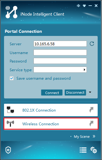
1. Run the iNode client, and then click Wireless Connection, as shown in Figure 2.
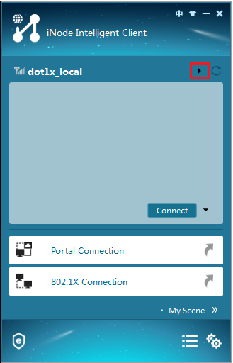
2. Click triangle icon in the wireless connection title bar, as shown in Figure 3.
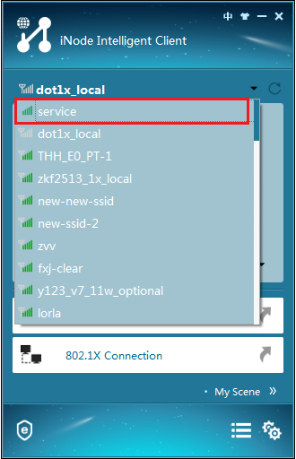
3. Double-click the wireless service with SSID service, as shown in Figure 4.
Figure 4 Selecting a wireless service
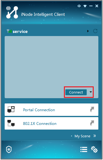
4. Click Connect, as shown in Figure 5.
Figure 5 Connecting to the wireless network
Configuring 802.1X authentication
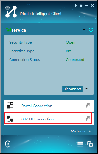
1. Click 802.1X Connection, as shown in Figure 6.
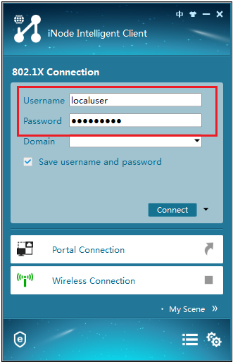
2. Enter username localuser and password localpass, as shown in Figure 7.
Figure 7 Entering the username and password
3. Click the inverted triangle icon next to Connect and select Properties.
4. In the dialog box that opens, select a wireless NIC and clear the option for uploading the client version.
5. Return to the iNode 802.1X connection screen.
6. Click Connect.
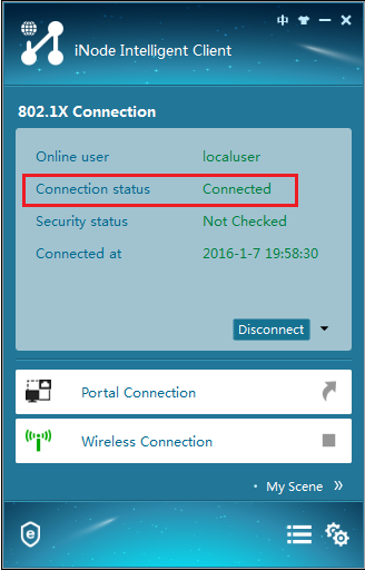
The iNode client displays the connection state as shown in Figure 8.
Figure 8 Successful 802.1X authentication
Verifying the configuration
# Display online 802.1X user information.
[AC] display dot1x connection
User MAC address : 0015-00bf-e84d
AP name : office
Radio ID : 1
SSID : service
BSSID : 741f-4ad4-1fe0
Username : localuser
Authentication domain : bbb
IPv4 address : 2.2.1.3
Authentication method : CHAP
Initial VLAN : 200
Authorization VLAN : 200
Authorization ACL number : N/A
Authorization user profile : N/A
Termination action : N/A
Session timeout period : N/A
Online from : 2019/12/04 17:37:55
Online duration : 0h 4m 20s
# Display service template information.
[AC] display wlan service-template service
Service template name : service
SSID : service
SSID-hide : Disabled
User-isolation : Disabled
Service template status : Enabled
Maximum clients per BSS : Not configured
Frame format : Dot3
Seamless roam status : Disabled
Seamless roam RSSI threshold : 50
Seamless roam RSSI gap : 20
VLAN ID : 200
AKM mode : Not configured
Security IE : Not configured
Cipher suite : Not configured
TKIP countermeasure time : 0 sec
PTK lifetime : 43200 sec
GTK rekey : Enabled
GTK rekey method : Time-based
GTK rekey time : 86400 sec
GTK rekey client-offline : Disabled
User authentication mode : 802.1X
Intrusion protection : Disabled
Intrusion protection mode : Temporary-block
Temporary block time : 180 sec
Temporary service stop time : 20 sec
Fail VLAN ID : Not configured
802.1X handshake : Disabled
802.1X handshake secure : Disabled
802.1X domain : bbb
MAC-auth domain : Not configured
Max 802.1X users : 4096
Max MAC-auth users : 4096
802.1X re-authenticate : Disabled
Authorization fail mode : Online
Accounting fail mode : Online
Authorization : Permitted
Key derivation : SHA1
PMF status : Disabled
Hotspot policy number : Not configured
Forwarding policy status : Disabled
Forwarding policy name : Not configured
FT status : Disabled
QoS trust : Port
QoS priority : 0
Configuration files
· AC:
#
vlan 100
#
vlan 200
#
wlan service-template service
ssid service
vlan 200
client-security authentication-mode dot1x
dot1x domain bbb
service-template enable
#
interface Vlan-interface100
ip address 2.2.2.1 255.255.255.0
#
interface Vlan-interface200
ip address 2.2.1.1 255.255.255.0
#
domain bbb
authentication lan-access local
authorization lan-access local
accounting lan-access local
#
local-user localuser class network
password cipher $c$3$+5Yra0KsaLci/RxEa4lyYKxxiw6jwMCcOg==
service-type lan-access
#
wlan ap office model WA4320i-ACN
serial-id 210235A1GQC158004457
radio 1
radio enable
service-template service
#
· Switch:
#
dhcp enable
#
vlan 100
#
vlan 200
#
dhcp server ip-pool 100
gateway-list 2.2.2.1
network 2.2.2.0 mask 255.255.255.0
#
dhcp server ip-pool 200
gateway-list 2.2.1.1
network 2.2.1.0 mask 255.255.255.0
dns-list 2.2.1.1
#
interface Vlan-interface100
ip address 2.2.2.100 255.255.255.0
#
interface Vlan-interface200
ip address 2.2.1.2 255.255.255.0
#
interface GigabitEthernet1/0/1
port link-type trunk
port trunk permit vlan 1 100 200
#
interface GigabitEthernet1/0/2
port link-type access
port access permit vlan 100
poe enable
#
Related documentation
· AP and WT Management Configuration Guide in H3C Access Controllers Configuration Guides
· AP and WT Management Command Reference in H3C Access Controllers Command References
· Network Connectivity Configuration Guide in H3C Access Controllers Configuration Guides
· Network Connectivity Command Reference in H3C Access Controllers Command References
· User Access and Authentication Configuration Guide in H3C Access Controllers Configuration Guides
· User Access and Authentication Command Reference in H3C Access Controllers Command References
· WLAN Access Configuration Guide in H3C Access Controllers Configuration Guides
· WLAN Access Command Reference in H3C Access Controllers Command References
