- Table of Contents
-
- 03-CLI configuration examples (AC+fit AP)
- 01-HTTPS Login Configuration Examples
- 02-SSH Configuration Examples
- 03-License Management Configuration Examples
- 04-IPv6 URL Redirection Configuration Examples
- 05-AP Association with the AC at Layer 2 Configuration Examples
- 06-AP Association with the AC at Layer 2 (IPv6) Configuration Examples
- 07-Auto AP Configuration Examples
- 08-AP Association with the AC at Layer 3 Configuration Examples
- 09-AP Association with the AC at Layer 3 (IPv6) Configuration Examples
- 10-WEP Encryption Configuration Examples
- 11-PSK Encryption Configuration Examples
- 12-WPA3-SAE PSK Encryption Configuration Examples
- 13-WLAN Access (IPv6) Configuration Examples
- 14-Policy-Based Forwarding with Dual Gateways Configuration Examples
- 15-Scheduled Configuration Deployment by AP Group Configuration Examples
- 16-Inter-AC Roaming with Static Client VLAN Allocation Configuration Examples
- 17-Service Template and Radio Binding Configuration Examples
- 18-Scheduled WLAN Access Services Configuration Examples
- 19-Local Portal Authentication Configuration Examples
- 20-HTTPS-Based Local Portal Authentication Configuration Examples
- 21-Remote Portal Authentication Configuration Examples
- 22-Local Portal Authentication through LDAP Server Configuration Examples
- 23-Local Portal Authentication and SSID-based Authentication Page Pushing Configuration Examples
- 24-Local Portal MAC-Trigger Authentication Configuration Examples
- 25-Portal MAC-Trigger Authentication Configuration Examples
- 26-Local Forwarding Mode and Local Portal MAC-Trigger Authentication Configuration Examples
- 27-Local Portal Authentication (IPv6) Configuration Examples
- 28-Local Portal Authentication through LDAP Server (IPv6) Configuration Examples
- 29-Remote Portal Authentication (IPv6) Configuration Examples
- 30-Portal MAC-Trigger Authentication (IPv6) Configuration Example
- 31-Remote Portal Authentication with User Profile Authorization Configuration Examples
- 32-Portal Fail-Permit Configuration Examples
- 33-Local MAC Authentication Configuration Examples
- 34-MAC Authentication and PSK Authentication Configuration Examples
- 35-Remote MAC and Portal Authentication and Transparent Authentication Configuration Examples
- 36-Remote AP and Remote Portal MAC-Trigger Authentication Configuration Examples
- 37-MAC Authentication with Guest VLAN Assignment Configuration Examples
- 38-MAC Authentication with Guest VLAN Assignment (IPv6) Configuration Examples
- 39-Local MAC-Then-802.1X Authentication Configuration Examples
- 40-Local 802.1X Authentication Configuration Examples
- 41-Local RADIUS-Based 802.1X Authentication in EAP Relay Mode Configuration Examples
- 42-Remote 802.1X Authentication Configuration Examples
- 43-Remote 802.1X Authentication (IPv6) Configuration Examples
- 44-Remote 802.1X Authentication in WPA3-Enterprise Mode Configuration Examples
- 45-802.1X Authentication with ACL Assignment Through IMC Server Configuration Examples
- 46-802.1X Authentication with User Profile Assignment Through IMC Server Configuration Examples
- 47-EAD Authentication Configuration Examples
- 48-EAD Authentication (IPv6) Configuration Examples
- 49-Local Forwarding Mode and Local Portal Authentication Configuration Examples
- 50-Local Forwarding Mode Direct Portal Authentication Configuration Examples
- 51-Local Forwarding Mode Direct Portal Authentication (IPv6) Configuration Examples
- 52-Local Forwarding Configuration Examples
- 53-Remote AP Configuration Examples
- 54-WIPS Configuration Examples
- 55-WIPS Countermeasures Against All SSIDs Configuration Examples
- 56-IP Source Guard (IPv4) Configuration Examples
- 57-IP Source Guard (IPv6) Configuration Examples
- 58-IRF Setup with Members Directly Connected Configuration Examples
- 59-IRF Setup with Members Not Directly Connected Configuration Examples
- 60-IRF Setup with Members in One Chassis Configuration Examples
- 61-IRF Setup with Members in Different Chassis Configuration Examples
- 62-Dual-Link Backup Configuration Examples
- 63-Remote 802.1X Auth on AC Hierarchy Network with Dual-Link Central AC Backup Configuration Examples
- 64-Remote Portal Auth on AC Hierarchy Network with Dual-Link Central AC Backup Configuration Examples
- 65-OAuth-Based Portal MAC-Trigger Auth on Local-Forwarding Dual-Link Backup Configuration Examples
- 66-Dual-Link Backup OAuth-Based Portal Auth in Local Forwarding Configuration Examples
- 67-Dual-Link Backup Remote Portal MAC-Trigger Auth in Local Forwarding Configuration Examples
- 68-Dual-Link Backup Remote Portal and Transparent MAC Auth in Local Forwarding Configuration Examples
- 69-Dual-Link Backup Remote Portal Auth in Local Forwarding Configuration Examples
- 70-Dual-Link Backup Remote Portal and MAC Auth in Centralized Forward Configuration Examples
- 71-Dual-Link Backup Remote Portal Auth in Centralized Forwarding Configuration Examples
- 72-Dual-Link Backup Lightweight Portal Auth in Centralized Forwarding Configuration Examples
- 73-Dual-Link Backup OAuth-Based Portal Auth in Centralized Forwarding Configuration Examples
- 74-Dual-Link Backup Remote Portal MAC-Trigger Auth in Centralized Forwarding Configuration Examples
- 75-Remote 802.1X Auth on a Dual-Link AC Backup Network Configuration Examples
- 76-Remote MAC Auth on a Dual-Link AC Backup Network Configuration Examples
- 77-Remote 802.1X Authentication on an AC Hierarchy Network Configuration Examples
- 78-Remote 802.1X Authentication Configuration Examples
- 79-WLAN Probe Configuration Examples
- 80-Multicast Optimization Configuration Examples
- 81-Client Rate Limiting Configuration Examples
- 82-Inter-AC Roaming Configuration Examples
- 83-Inter-AC Roaming (IPv6) Configuration Examples
- 84-WLAN Load Balancing Configuration Examples
- 85-Static Blacklist Configuration Examples
- 86-Client Quantity Control Configuration Examples
- 87-AP License Synchronization Configuration Examples
- 88-iBeacon Management Configuration Examples
- 89-Mesh Link Establishment Between a Fit AP and a Fat AP Configuration Examples
- 90-Mesh Link Establishment Between Fit APs Configuration Examples
- 91-Auto-DFS and Auto-TPC Configuration Examples
- 92-AP Image Downloading Configuration Examples
- 93-Dual-Uplink Interfaces Configuration Guide
- 94-Internal-to-External Access Through NAT Configuration Examples
- 95-Layer 2 Static Aggregation Configuration Examples
- 96-Layer 2 Multicast Configuration Examples
- 97-Static VLAN Allocation Configuration Examples
- 98-URL Redirection Configuration Examples
- Related Documents
-
| Title | Size | Download |
|---|---|---|
| 87-AP License Synchronization Configuration Examples | 95.03 KB |
|
|
|
H3C Access Controllers |
|
Comware 7 AP License Synchronization |
|
Configuration Examples |
Copyright © 2022 New H3C Technologies Co., Ltd. All rights reserved.
No part of this manual may be reproduced or transmitted in any form or by any means without prior written consent of New H3C Technologies Co., Ltd.
Except for the trademarks of New H3C Technologies Co., Ltd., any trademarks that may be mentioned in this document are the property of their respective owners.
The information in this document is subject to change without notice.
Introduction
The following information provides an AP license synchronization configuration example.
Prerequisites
The following information applies to Comware 7-based access controllers and access points. Procedures and information in the examples might be slightly different depending on the software or hardware version of the access controllers and access points.
The configuration examples were created and verified in a lab environment, and all the devices were started with the factory default configuration. When you are working on a live network, make sure you understand the potential impact of every command on your network.
The following information is provided based on the assumption that you have basic knowledge of AP license synchronization.
Example: Configuring AP license synchronization
Network requirements
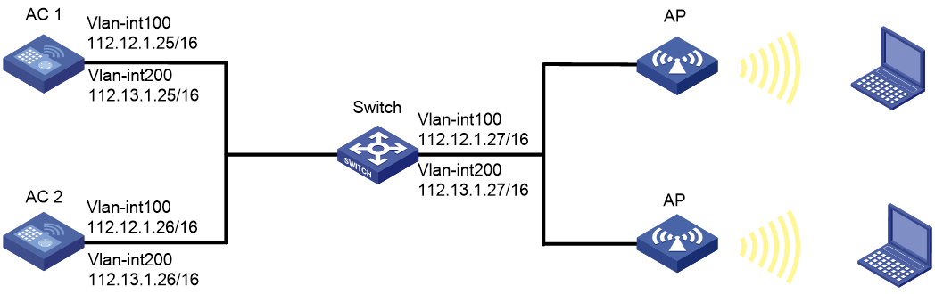
As shown in Figure 1, the APs connect to AC 1 and AC 2 through the switch and the APs provide wireless service for clients. Set the SSID to service and enable AP license synchronization on AC 1 and AC 2. The two ACs back up licenses for each other.
Configuration restrictions and guidelines
When the master AC fails, the backup AC will take over and becomes the new master AC. The licenses synchronized to the new master AC will be valid for a 30-day grace period.
Configuration procedures
Configuring the AC 1
1. Configure interfaces on the AC 1:
# Configure VLAN-interface 100 and assign it an IP address. The AC 1 will use this IP address to establish CAPWAP tunnels with APs.
<AC1> system-view
[AC1] vlan 100
[AC1-vlan100] quit
[AC1] interface vlan-interface 100
[AC1-Vlan-interface100] ip address 112.12.1.25 16
[AC1-Vlan-interface100] quit
# Configure VLAN-interface 200 and assign it an IP address. The AC 1 will use VLAN 200 for client access.
[AC1] vlan 200
[AC1-vlan200] quit
[AC1] interface vlan-interface 200
[AC1-Vlan-interface200] ip address 112.13.1.25 16
[AC1-Vlan-interface200] quit
# Configure GigabitEthernet 1/0/1 that connects the AC 1 to the switch as a trunk port.
[AC1] interface gigabitethernet1/0/1
[AC1-GigabitEthernet1/0/1] port link-type trunk
# Remove the trunk port from VLAN 1, and assign the port to VLANs 100 and 200.
[AC1-GigabitEthernet1/0/1] undo port trunk permit vlan 1
[AC1-GigabitEthernet1/0/1] port trunk permit vlan 100 200
# Specify the PVID of the trunk port as VLAN 100.
[AC1-GigabitEthernet1/0/1] port trunk pvid vlan 100
[AC1-GigabitEthernet1/0/1] quit
# Enable AP license synchronization on AC 1 and configure AC 1 as the master AC.
[AC1] wlan ap-license-group
[AC1-wlan-ap-license-group] local ip 112.12.1.25
[AC1-wlan-ap-license-group] member ip 112.12.1.26
[AC1-wlan-ap-license-group] ap-license-synchronization enable
[AC1-wlan-ap-license-group] quit
2. Configure the wireless service:
# Create wireless service template service and enter its view.
[AC1] wlan service-template service
# Set the SSID to service.
[AC1-wlan-st-service] ssid service
# Assign clients coming online through service template service to VLAN 200.
[AC1-wlan-st-service] vlan 200
# Enable service template service.
[AC1-wlan-st-service] service-template enable
[AC1-wlan-st-service] quit
3. Create APs and bind service template service to radio interfaces of the APs. (Details not shown.)
Configuring the AC 2
1. Configure interfaces on the AC 2:
# Configure VLAN-interface 100 and assign it an IP address. The AC 2 will use this IP address to establish CAPWAP tunnels with APs.
<AC2> system-view
[AC2] vlan 100
[AC2-vlan100] quit
[AC2] interface vlan-interface 100
[AC2-Vlan-interface100] ip address 112.12.1.26 16
[AC2-Vlan-interface100] quit
# Configure VLAN-interface 200 and assign it an IP address. The AC 2 will use VLAN 200 for client access.
[AC2] vlan 200
[AC2-vlan200] quit
[AC2] interface vlan-interface 200
[AC2-Vlan-interface200] ip address 112.13.1.26 16
[AC2-Vlan-interface200] quit
# Configure GigabitEthernet 1/0/1 that connects the AC 2 to the switch as a trunk port.
[AC2] interface gigabitethernet1/0/1
[AC2-GigabitEthernet1/0/1] port link-type trunk
# Remove the trunk port from VLAN 1, and assign the port to VLANs 100 and 200.
[AC2-GigabitEthernet1/0/1] undo port trunk permit vlan 1
[AC2-GigabitEthernet1/0/1] port trunk permit vlan 100 200
# Specify the PVID of the trunk port as VLAN 100.
[AC2-GigabitEthernet1/0/1] port trunk pvid vlan 100
[AC2-GigabitEthernet1/0/1] quit
# Enable AP license synchronization on AC 2 and configure AC 2 as the master AC.
[AC2] wlan ap-license-group
[AC2-wlan-ap-license-group] local ip 112.12.1.26
[AC2-wlan-ap-license-group] member ip 112.12.1.25
[AC2-wlan-ap-license-group] ap-license-synchronization enable
[AC2-wlan-ap-license-group] quit
2. Configure the wireless service:
# Create wireless service template service and enter its view.
[AC2] wlan service-template service
# Set the SSID to service.
[AC2-wlan-st-service] ssid service
# Assign clients coming online through service template service to VLAN 200.
[AC2-wlan-st-service] vlan 200
# Enable service template service.
[AC2-wlan-st-service] service-template enable
[AC2-wlan-st-service] quit
3. Create APs and bind service template service to radio interfaces of the APs. (Details not shown.)
Configuring the switch
# Create VLAN 100 and VLAN 200. The switch will use VLAN 100 to forward the traffic on CAPWAP tunnels between the AC and APs, and will use VLAN 200 to forward client traffic.
<Switch> system-view
[Switch] vlan 100
[Switch-vlan100] quit
[Switch] vlan 200
[Switch-vlan200] quit
# Configure GigabitEthernet 1/0/1 that connects the switch to the AC 1 as a trunk port.
[Switch] interface gigabitethernet1/0/1
[Switch-GigabitEthernet1/0/1] port link-type trunk
# Remove the trunk port from VLAN 1, and assign the port to VLAN 100.
[Switch-GigabitEthernet1/0/1] undo port trunk permit vlan 1
[Switch-GigabitEthernet1/0/1] port trunk permit vlan 100
# Specify the PVID of the trunk port as VLAN 100.
[Switch-GigabitEthernet1/0/1] port trunk pvid vlan 100
[Switch-GigabitEthernet1/0/1] quit
# Configure GigabitEthernet 1/0/2 that connects the switch to the AC 2 as a trunk port.
[Switch] interface gigabitethernet1/0/2
[Switch-GigabitEthernet1/0/2] port link-type trunk
# Remove the trunk port from VLAN 1, and assign the port to VLAN 100.
[Switch-GigabitEthernet1/0/2] undo port trunk permit vlan 1
[Switch-GigabitEthernet1/0/2] port trunk permit vlan 100
# Specify the PVID of the trunk port as VLAN 100.
[Switch-GigabitEthernet1/0/2] port trunk pvid vlan 100
[Switch-GigabitEthernet1/0/2] quit
# Configure the interface GigabitEthernet 1/0/3 that is connected to APs as an access port, and assign the port to VLAN 100.
[Switch] interface gigabitethernet1/0/3
[Switch-GigabitEthernet1/0/3] port link-type access
[Switch-GigabitEthernet1/0/3] port access vlan 100
# Enable PoE on GigabitEthernet 1/0/3.
[Switch-GigabitEthernet1/0/3] poe enable
[Switch-GigabitEthernet1/0/3] quit
# Specify 112.12.1.27/16 as the IP address of the VLAN 100.
[Switch] interface vlan-interface 100
[Switch-Vlan-interface100] ip address 112.12.1.27 16
[Switch-Vlan-interface100] quit
# Specify 112.13.1.27/16 as the IP address of the VLAN 200.
[Switch] interface vlan-interface 200
[Switch-Vlan-interface200] ip address 112.13.1.27 16
[Switch-Vlan-interface200] quit
# Enable DHCP.
[Switch] dhcp enable
# Create DHCP IP pool 100 to assign IP addresses to APs, and specify the IP address range for the IP pool.
[Switch] dhcp server ip-pool 100
[Switch-dhcp-pool-100] network 112.12.0.0 mask 255.255.0.0
# Specify gateway IP address 112.12.1.27 in the DHCP IP pool.
[Switch-dhcp-pool-100] gateway-list 112.12.1.27
[Switch-dhcp-pool-100] quit
# Create DHCP IP pool 200 to assign IP addresses to clients, and specify the IP address range for the DHCP IP pool.
[Switch] dhcp server ip-pool 200
[Switch-dhcp-pool-200] network 112.13.0.0 mask 255.255.255.0
# Specify gateway IP address 112.13.1.27 in the DHCP IP pool.
[Switch-dhcp-pool-200] gateway-list 112.13.1.27
# Specify the DNS server according to the actual network plan. In this example, the gateway is specified as the DNS server.
[Switch-dhcp-pool-200] dns-list 112.13.1.27
[Switch-dhcp-pool-200] quit
Verifying the configuration
1. Display AP license synchronization group information on AC 1.
<AC1> display wlan ap-license-group
Group total licenses: 32
Group used licenses: 2
AP license synchronization: Enabled
Local IP: 112.12.1.25
Local role: Master
Member information:
IP address Total Used Member role State Online duration
112.12.1.26 16 0 Master UP 10hr 22min 04sec
2. Display AP license synchronization group information on AC 2.
<AC2> display wlan ap-license-group
Group total licenses: 32
Group used licenses: 2
AP license synchronization: Enabled
Local IP: 112.12.1.26
Local role: Master
Member information:
IP address Total Used Member role State Online duration
112.12.1.25 16 2 Master UP 10hr 22min 04sec
3. When AC 2 fails, AC 1 takes over and the sum of licenses remains 32.
<AC1> display wlan ap-license-group
Group total licenses: 32
Group used licenses: 2
AP license synchronization: Enabled
Local IP: 112.12.1.25
Local role: Master
Member information:
IP address Total Used Member role State Online duration
112.12.1.26 16 0 Master DOWM 00hr 00min 00sec
Configuration files
· AC 1:
#
vlan 100
#
vlan 200
#
wlan service-template service
ssid service
vlan 200
service-template enable
#
interface Vlan-interface100
ip address 112.12.1.25 255.255.0.0
#
interface Vlan-interface200
ip address 112.13.1.25 255.255.0.0
#
interface GigabitEthernet1/0/1
port link-type trunk
undo port trunk permit vlan 1
port trunk permit vlan 100 200
port trunk pvid vlan 100
#
wlan ap-license-group
local ip 112.12.1.25
member ip 112.12.1.26
ap-license-synchronization enable
#
· AC 2:
#
vlan 100
#
vlan 200
#
wlan service-template service
ssid service
vlan 200
service-template enable
#
interface Vlan-interface100
ip address 112.12.1.26 255.255.0.0
#
interface Vlan-interface200
ip address 112.13.1.26 255.255.0.0
#
interface GigabitEthernet1/0/1
port link-type trunk
undo port trunk permit vlan 1
port trunk permit vlan 100 200
port trunk pvid vlan 100
#
wlan ap-license-group
local ip 112.12.1.26
member ip 112.12.1.25
ap-license-synchronization enable
#
· Switch:
#
dhcp enable
#
vlan 100
#
vlan 200
#
dhcp server ip-pool vlan100
gateway-list 112.12.1.27
network 112.12.0.0 mask 255.255.0.0
#
dhcp server ip-pool vlan200
gateway-list 112.13.1.27
network 112.13.0.0 mask 255.255.255.0
dns-list 112.13.1.27
#
interface Vlan-interface100
ip address 112.12.1.27 255.255.0.0
#
interface Vlan-interface200
ip address 112.13.1.27 255.255.255.0
#
interface GigabitEthernet1/0/1
port link-type trunk
undo port trunk permit vlan 1
port trunk permit vlan 100
port trunk pvid vlan 100
#
Related documentation
· License Management Command Reference in H3C Access Controllers Command References
· License Management Configuration Guide in H3C Access Controllers Configuration Guides
