- Table of Contents
-
- 03-CLI configuration examples (AC+fit AP)
- 01-HTTPS Login Configuration Examples
- 02-SSH Configuration Examples
- 03-License Management Configuration Examples
- 04-IPv6 URL Redirection Configuration Examples
- 05-AP Association with the AC at Layer 2 Configuration Examples
- 06-AP Association with the AC at Layer 2 (IPv6) Configuration Examples
- 07-Auto AP Configuration Examples
- 08-AP Association with the AC at Layer 3 Configuration Examples
- 09-AP Association with the AC at Layer 3 (IPv6) Configuration Examples
- 10-WEP Encryption Configuration Examples
- 11-PSK Encryption Configuration Examples
- 12-WPA3-SAE PSK Encryption Configuration Examples
- 13-WLAN Access (IPv6) Configuration Examples
- 14-Policy-Based Forwarding with Dual Gateways Configuration Examples
- 15-Scheduled Configuration Deployment by AP Group Configuration Examples
- 16-Inter-AC Roaming with Static Client VLAN Allocation Configuration Examples
- 17-Service Template and Radio Binding Configuration Examples
- 18-Scheduled WLAN Access Services Configuration Examples
- 19-Local Portal Authentication Configuration Examples
- 20-HTTPS-Based Local Portal Authentication Configuration Examples
- 21-Remote Portal Authentication Configuration Examples
- 22-Local Portal Authentication through LDAP Server Configuration Examples
- 23-Local Portal Authentication and SSID-based Authentication Page Pushing Configuration Examples
- 24-Local Portal MAC-Trigger Authentication Configuration Examples
- 25-Portal MAC-Trigger Authentication Configuration Examples
- 26-Local Forwarding Mode and Local Portal MAC-Trigger Authentication Configuration Examples
- 27-Local Portal Authentication (IPv6) Configuration Examples
- 28-Local Portal Authentication through LDAP Server (IPv6) Configuration Examples
- 29-Remote Portal Authentication (IPv6) Configuration Examples
- 30-Portal MAC-Trigger Authentication (IPv6) Configuration Example
- 31-Remote Portal Authentication with User Profile Authorization Configuration Examples
- 32-Portal Fail-Permit Configuration Examples
- 33-Local MAC Authentication Configuration Examples
- 34-MAC Authentication and PSK Authentication Configuration Examples
- 35-Remote MAC and Portal Authentication and Transparent Authentication Configuration Examples
- 36-Remote AP and Remote Portal MAC-Trigger Authentication Configuration Examples
- 37-MAC Authentication with Guest VLAN Assignment Configuration Examples
- 38-MAC Authentication with Guest VLAN Assignment (IPv6) Configuration Examples
- 39-Local MAC-Then-802.1X Authentication Configuration Examples
- 40-Local 802.1X Authentication Configuration Examples
- 41-Local RADIUS-Based 802.1X Authentication in EAP Relay Mode Configuration Examples
- 42-Remote 802.1X Authentication Configuration Examples
- 43-Remote 802.1X Authentication (IPv6) Configuration Examples
- 44-Remote 802.1X Authentication in WPA3-Enterprise Mode Configuration Examples
- 45-802.1X Authentication with ACL Assignment Through IMC Server Configuration Examples
- 46-802.1X Authentication with User Profile Assignment Through IMC Server Configuration Examples
- 47-EAD Authentication Configuration Examples
- 48-EAD Authentication (IPv6) Configuration Examples
- 49-Local Forwarding Mode and Local Portal Authentication Configuration Examples
- 50-Local Forwarding Mode Direct Portal Authentication Configuration Examples
- 51-Local Forwarding Mode Direct Portal Authentication (IPv6) Configuration Examples
- 52-Local Forwarding Configuration Examples
- 53-Remote AP Configuration Examples
- 54-WIPS Configuration Examples
- 55-WIPS Countermeasures Against All SSIDs Configuration Examples
- 56-IP Source Guard (IPv4) Configuration Examples
- 57-IP Source Guard (IPv6) Configuration Examples
- 58-IRF Setup with Members Directly Connected Configuration Examples
- 59-IRF Setup with Members Not Directly Connected Configuration Examples
- 60-IRF Setup with Members in One Chassis Configuration Examples
- 61-IRF Setup with Members in Different Chassis Configuration Examples
- 62-Dual-Link Backup Configuration Examples
- 63-Remote 802.1X Auth on AC Hierarchy Network with Dual-Link Central AC Backup Configuration Examples
- 64-Remote Portal Auth on AC Hierarchy Network with Dual-Link Central AC Backup Configuration Examples
- 65-OAuth-Based Portal MAC-Trigger Auth on Local-Forwarding Dual-Link Backup Configuration Examples
- 66-Dual-Link Backup OAuth-Based Portal Auth in Local Forwarding Configuration Examples
- 67-Dual-Link Backup Remote Portal MAC-Trigger Auth in Local Forwarding Configuration Examples
- 68-Dual-Link Backup Remote Portal and Transparent MAC Auth in Local Forwarding Configuration Examples
- 69-Dual-Link Backup Remote Portal Auth in Local Forwarding Configuration Examples
- 70-Dual-Link Backup Remote Portal and MAC Auth in Centralized Forward Configuration Examples
- 71-Dual-Link Backup Remote Portal Auth in Centralized Forwarding Configuration Examples
- 72-Dual-Link Backup Lightweight Portal Auth in Centralized Forwarding Configuration Examples
- 73-Dual-Link Backup OAuth-Based Portal Auth in Centralized Forwarding Configuration Examples
- 74-Dual-Link Backup Remote Portal MAC-Trigger Auth in Centralized Forwarding Configuration Examples
- 75-Remote 802.1X Auth on a Dual-Link AC Backup Network Configuration Examples
- 76-Remote MAC Auth on a Dual-Link AC Backup Network Configuration Examples
- 77-Remote 802.1X Authentication on an AC Hierarchy Network Configuration Examples
- 78-Remote 802.1X Authentication Configuration Examples
- 79-WLAN Probe Configuration Examples
- 80-Multicast Optimization Configuration Examples
- 81-Client Rate Limiting Configuration Examples
- 82-Inter-AC Roaming Configuration Examples
- 83-Inter-AC Roaming (IPv6) Configuration Examples
- 84-WLAN Load Balancing Configuration Examples
- 85-Static Blacklist Configuration Examples
- 86-Client Quantity Control Configuration Examples
- 87-AP License Synchronization Configuration Examples
- 88-iBeacon Management Configuration Examples
- 89-Mesh Link Establishment Between a Fit AP and a Fat AP Configuration Examples
- 90-Mesh Link Establishment Between Fit APs Configuration Examples
- 91-Auto-DFS and Auto-TPC Configuration Examples
- 92-AP Image Downloading Configuration Examples
- 93-Dual-Uplink Interfaces Configuration Guide
- 94-Internal-to-External Access Through NAT Configuration Examples
- 95-Layer 2 Static Aggregation Configuration Examples
- 96-Layer 2 Multicast Configuration Examples
- 97-Static VLAN Allocation Configuration Examples
- 98-URL Redirection Configuration Examples
- Related Documents
-
| Title | Size | Download |
|---|---|---|
| 22-Local Portal Authentication through LDAP Server Configuration Examples | 105.34 KB |
|
|
|
H3C Access Controllers |
|
Comware 7 Local Portal Authentication Through the LDAP Server |
|
Configuration Examples |
|
|
Copyright © 2022 New H3C Technologies Co., Ltd. All rights reserved.
No part of this manual may be reproduced or transmitted in any form or by any means without prior written consent of New H3C Technologies Co., Ltd.
Except for the trademarks of New H3C Technologies Co., Ltd., any trademarks that may be mentioned in this document are the property of their respective owners.
The information in this document is subject to change without notice.
Introduction
The following information provides an example of configuring the local portal service on the AC to send wireless user information to the LDAP server for authentication.
Prerequisites
The following information applies to Comware 7-based access controllers and access points. Procedures and information in the examples might be slightly different depending on the software or hardware version of the access controllers and access points.
The configuration examples were created and verified in a lab environment, and all the devices were started with the factory default configuration. When you are working on a live network, make sure you understand the potential impact of every command on your network.
The following information is provided based on the assumption that you have basic knowledge of AAA, portal, and WLAN.
Example: Configuring local portal authentication through the LDAP server
Network configuration
As shown in Figure 1, the AP and the client obtain IP addresses from the DHCP server.
Configuration requirements are as follows:
· Configure the local portal service on the AC to provide authentication pages for clients.
· Use the LDAP server to authenticate the clients.

Restrictions and guidelines
Configure routing to make sure the devices can reach one another.
Use the serial ID labeled on the AP's rear panel to specify an AP.
Edit the authentication pages, compress them to a .zip file (this example uses abc.zip), and then upload the file to the root directory of the storage medium of the AC. On the AC, you must specify this file as the default authentication page file.
To change the default authentication page file, you must first execute the undo default-logon-page command, and then specify a new default authentication page file.
Procedures
Configuring the AC
1. Configuring VLANs and interfaces:
# Create VLAN 100 and VLAN-interface 100. Assign the VLAN interface an IP address. The AC will use this IP address to establish a CAPWAP tunnel with the AP.
<AC> system-view
[AC] vlan 100
[AC-vlan100] quit
[AC] interface vlan-interface 100
[AC-Vlan-interface100] ip address 2.2.1.1 24
[AC-Vlan-interface100] quit
# Create VLAN 200 and VLAN-interface 200. Assign the VLAN interface an IP address. This VLAN will be used for wireless client access.
[AC] vlan 200
[AC-vlan200] quit
[AC] interface vlan-interface 200
[AC-Vlan-interface200] ip address 2.2.2.1 24
[AC-Vlan-interface200] quit
# Configure GigabitEthernet 1/0/1 (the port connected to the switch) as a trunk port. Assign the port to VLAN 100 and VLAN 200.
[AC] interface gigabitethernet 1/0/1
[AC-GigabitEthernet1/0/1] port link-type trunk
[AC-GigabitEthernet1/0/1] port trunk permit vlan 100 200
[AC-GigabitEthernet1/0/1] quit
2. Configure the LDAP scheme:
# Create an LDAP server named ldap and enter its view.
[AC] ldap server ldap
# Specify the administrator DN.
[AC-ldap-server-ldap] login-dn cn=administrator,cn=users,dc=ldap,dc=com
# Specify the base DN for user search.
[AC-ldap-server-ldap] search-base-dn dc=ldap,dc=com
# Specify the IP address of the LDAP server.
[AC-ldap-server-ldap] ip 192.168.0.112
# Specify the administrator password.
[AC-ldap-server-ldap] login-password simple 123456
[AC-ldap-server-ldap] quit
# Create an LDAP scheme named ldap and enter its view.
[AC] ldap scheme ldap
# Specify ldap as the LDAP authentication server.
[AC-ldap-ldap] authentication-server ldap
[AC-ldap-ldap] quit
# Create an ISP domain named ldap and enter its view.
[AC] domain ldap
# Configure the authentication method as LDAP and the authentication and accounting methods as none for portal users in ISP domain ldap.
[AC-isp-ldap]authentication portal ldap-scheme ldap
[AC-isp-ldap] authorization portal none
[AC-isp-ldap] accounting portal none
# Configure the idle cut feature for users in ISP domain ldap. Log out a user if the user's traffic is less than 1024 bytes in 15 minutes.
[AC-isp-ldap] authorization-attribute idle-cut 15 1024
[AC-isp-ldap] quit
3. Configure portal authentication:
# Create a portal Web server named newpt and specify http://2.2.2.1/portal as the server's URL.
[AC] portal web-server newpt
[AC-portal-websvr-newpt] url http://2.2.2.1/portal
[AC-portal-websvr-newpt] quit
# Create an HTTP-based local portal Web service.
[AC] portal local-web-server http
# Specify file abc.zip as the default authentication page file. (The file must already exist in the root directory of the storage medium of the AC.)
[AC–portal-local-websvr-http] default-logon-page abc.zip
[AC–portal-local-websvr-http] quit
# Configure two destination-based portal-free rules to permit the traffic destined for the DNS server.
[AC] portal free-rule 1 destination ip any udp 53
[AC] portal free-rule 2 destination ip any tcp 53
4. Configure the wireless service:
# Create a service template named st1 and enter its view.
[AC] wlan service-template st1
# Set the SSID of the service template to service.
[AC-wlan-st-st1] ssid service
# Assign clients coming online through the service template to VLAN 200.
[AC-wlan-st-st1] vlan 200
# Enable direct portal authentication on the service template.
[AC-wlan-st-st1] portal enable method direct
# Specify ISP domain ldap as the portal authentication domain.
[AC-wlan-st-st1] portal domain ldap
# Specify portal Web server newpt on the service template.
[AC-wlan-st-st1] portal apply web-server newpt
# Enable the service template.
[AC-wlan-st-st1] service-template enable
[AC-wlan-st-st1] quit
# Create an AP named officeap with model WA2620E-AGN, and specify the AP model and serial ID.
[AC] wlan ap officeap model WA2620E-AGN
[AC-wlan-ap-officeap] serial-id 21023529G007C000020
# Enter the view of radio 2.
[AC-wlan-ap-officeap] radio 2
# Bind service template st1 to radio 2.
[AC-wlan-ap-officeap-radio-2] service-template st1
[AC-wlan-ap-officeap-radio-2] radio enable
[AC-wlan-ap-officeap-radio-2] quit
[AC-wlan-ap-officeap] quit
Configuring the switch
# Create VLAN 100. The switch will use this VLAN to forward traffic on the CAPWAP tunnel between the AC and AP.
<Switch> system-view
[Switch] vlan 100
[Switch-vlan100] quit
# Create VLAN 200. The switch will use this VLAN to forward traffic of wireless clients.
[Switch] vlan 200
[Switch-vlan200] quit
# Configure GigabitEthernet 1/0/1 (the port connected to the AC) as a trunk port. Assign the trunk port to VLAN 100 and VLAN 200.
[Switch] interface gigabitethernet1/0/1
[Switch-GigabitEthernet1/0/1] port link-type trunk
[Switch-GigabitEthernet1/0/1] port trunk permit vlan 100 200
[Switch-GigabitEthernet1/0/1] quit
# Configure GigabitEthernet 1/0/2 (the port connected to the AP) as an access port. Assign the access port to VLAN 100.
[Switch] interface gigabitethernet1/0/2
[Switch-GigabitEthernet1/0/2] port link-type access
[Switch-GigabitEthernet1/0/2] port access vlan 100
# Enable PoE on the access port.
[Switch-GigabitEthernet1/0/2] poe enable
[Switch-GigabitEthernet1/0/2] quit
Configuring the LDAP server
This example uses Microsoft Windows 2003 Server Active Directory to illustrate the configuration on the LDAP server.
a. On the LDAP server, select Start > Control Panel > Administrative Tools.
b. Double-click Active Directory Users and Computers.
The Active Directory Users and Computers window opens.
c. From the navigation tree, click Users under the ldap.com node.
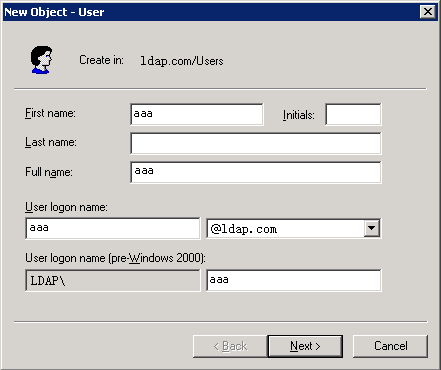
d. Select Action > New > User from the menu to open the dialog box for adding a user.
e. Enter logon name aaa and click Next.
Figure 2 Adding user aaa
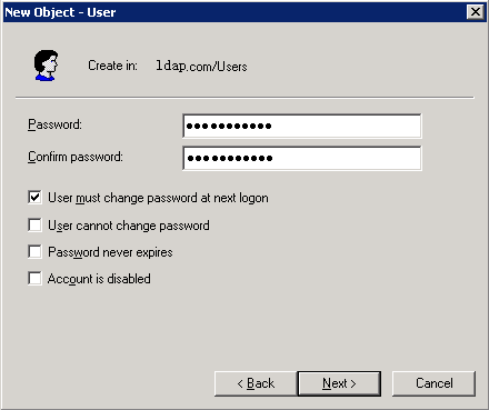
f. In the dialog box, enter password 123456, select options as needed, and click Next.
Figure 3 Setting the user's password
g. Click OK.
2. Add user aaa to user group Users:
a. From the navigation tree, click Users under the ldap.com node.
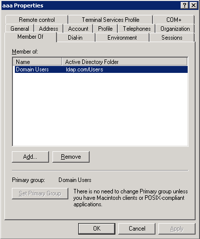
b. In the right pane, right-click user aaa and select Properties.
c. In the dialog box, click the Member Of tab and click Add.
Figure 4 Modifying user properties
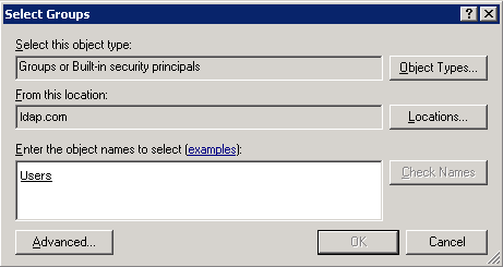
d. In the Select Groups dialog box, enter Users in the Enter the object names to select field, and click OK.
User aaa is added to group Users.
Figure 5 Adding user aaa to group Users
3. Configure the administrator password:
a. In the right pane, right-click user Administrator and select Set Password.
b. In the dialog box, enter the administrator password. (Details not shown.)
Verifying the configuration
# Open a Web browser such as IE on the wireless client. Type an IP address in the address bar and press Enter. The portal authentication page opens. Enter username aaa and password 123456 and then click Logon. User aaa passes authentication successfully.
# Display online portal users on the AC.
<AC> display portal user all
Index:17
State:ONLINE
SubState:NONE
ACL:3777
Work-mode:stand-alone
MAC IP Vlan Interface
----------------------------------------------------------------------------
2477-0341-f118 2.2.2.2 200 Vlan-interface200
Total 1 user(s) matched, 1 listed.
Configuration files
· AC:
#
vlan 100
#
vlan 200
#
wlan service-template st1
ssid service
vlan 200
portal enable method direct
portal domain ldap
portal apply web-server newpt
service-template enable
#
interface Vlan-interface100
ip address 2.2.1.1 255.255.255.0
#
interface Vlan-interface200
ip address 2.2.2.1 255.255.255.0
#
interface GigabitEthernet1/0/1
port link-type trunk
port trunk permit vlan 100 200
#
ldap server ldap
login-dn cn=administrator,cn=users,dc=ldap,dc=com
search-base-dn dc=ldap,dc=com
ip 192.168.0.112
login-password cipher $c$3$CEz2vKCnA2/51D8rFc/+nTNtOx8Gan+81Q==
#
ldap scheme ldap
authentication-server ldap
#
domain ldap
authorization-attribute idle-cut 15 1024
authentication portal ldap-scheme ldap
authorization portal none
accounting portal none
#
portal free-rule 1 destination ip any udp 53
portal free-rule 2 destination ip any tcp 53
#
portal web-server newpt
url http://2.2.2.1/portal
#
portal local-web-server http
default-logon-page abc.zip
#
wlan ap officeap model WA2620E-AGN
serial-id 21023529G007C000020
radio 2
radio enable
service-template st1
#
#
vlan 100
#
vlan 200
#
interface GigabitEthernet1/0/1
port link-mode bridge
port link-type trunk
port trunk permit vlan 100 200
#
interface GigabitEthernet1/0/2
port link-mode bridge
port access vlan 100
poe enable
#
Related documentation
· User Access and Authentication Command Reference in H3C Access Controllers Command References
· User Access and Authentication Configuration Guide in H3C Access Controllers Configuration Guides
· WLAN Access Command Reference in H3C Access Controllers Command References
· WLAN Access Configuration Guide in H3C Access Controllers Configuration Guides
