- Table of Contents
-
- H3C S7500 Series Operation Manual(Release 3100 Series)-(V1.04)
- 00-1Cover
- 00-2Overview
- 01-CLI Configuration
- 02-Login Configuration
- 03-Configuration File Management Configuration
- 04-VLAN Configuration
- 05-Extended VLAN Application Configuration
- 06-IP Address-IP Performance-IPX Configuration
- 07-GVRP Configuration
- 08-QinQ Configuration
- 09-Port Basic Configuration
- 10-Link Aggregation Configuration
- 11-Port Isolation Configuration
- 12-Port Binding Configuration
- 13-DLDP Configuration
- 14-MAC Address Table Configuration
- 15-MSTP Configuration
- 16-Routing Protocol Configuration
- 17-Multicast Configuration
- 18-802.1x Configuration
- 19-AAA-RADIUS-HWTACACS-EAD Configuration
- 20-Traffic Accounting Configuration
- 21-VRRP-HA Configuration
- 22-ARP Configuration
- 23-DHCP Configuration
- 24-ACL Configuration
- 25-QoS Configuration
- 26-Mirroring Configuration
- 27-Cluster Configuration
- 28-PoE Configuration
- 29-UDP-Helper Configuration
- 30-SNMP-RMON Configuration
- 31-NTP Configuration
- 32-SSH Terminal Service Configuration
- 33-File System Management Configuration
- 34-FTP and TFTP Configuration
- 35-Information Center Configuration
- 36-DNS Configuration
- 37-System Maintenance and Debugging Configuration
- 38-HWPing Configuration
- 39-RRPP Configuration
- 40-NAT-Netstream-Policy Routing Configuration
- 41-Telnet Protection Configuration
- 42-Hardware-Dependent Software Configuration
- Related Documents
-
| Title | Size | Download |
|---|---|---|
| 40-NAT-Netstream-Policy Routing Configuration | 367 KB |
Table of Contents
1.2.5 Special Protocols Supported by NAT
1.3.1 NAT Configuration Task List
1.3.2 Configuring a NAT Address Pool
1.3.4 Configuring Internal Server
1.3.5 Configuring Non-Standard Internal FTP Server
1.3.6 Configuring NAT Blacklist
1.3.7 Configuring NAT Connection Aging Time
1.3.8 Configuring NAT Security Logging
1.4 Displaying NAT Configuration
Chapter 2 Netstream Configuration
2.1.1 Introduction to Netstream
2.1.2 Implementation of Netstream
2.2.1 Netstream Configuration Task List
2.2.3 Entering Netstream Aggregation View
2.2.4 Enabling the Corresponding Aggregation Mode
2.2.5 Configuring the Address Information for Netstream Export Packets
2.2.6 Configuring the Version and AS Option for Netstream Export Packets
2.2.7 Configuring the DSCP Value for Netstream Export Packets
2.2.8 Configuring Netstream Entry Aging Time
2.2.9 Configuring the Ways to Update the Template for Version 9 Netstream Packets
2.3 Displaying Netstream Configuration
2.4 Netstream Configuration Example
Chapter 3 Policy Routing Configuration
3.2 Configuring Policy Routing
3.3 Displaying Policy Routing Configuration
3.4 Policy Routing Configuration Example
Chapter 1 NAT Configuration
When configuring NAT, go to these sections for information you are interested in:
l Displaying NAT Configuration
& Note:
Currently, the LS81VSNP boards installed in S7500 series switches support the NAT feature. In this manual, the LS81VSNP board is called LPU (line processing unit).
1.1 NAT Overview
As described in RFC1631, network address translation (NAT) is a procedure to translate the private IP address in packet header into a public IP address. With NAT, a private network that provides a great number of private addresses for its internal users to communicate with each other can use relatively smaller quantity of public addresses for its internal users to access the Internet. This allows private network users to access public networks and saves public IP address resources.
& Note:
Private IP addresses refer to the addresses used by the hosts in a private network to communicate to each other instead of to external networks. Public IP addresses refer to the globally unique, registered IP addresses that can be used on the Internet.
RFC1918 reserves the following three blocks of IP addresses for private networks:
l Class A: from 10.0.0.0 to 10.255.255.255
l Class B: from 172.16.0.0 to 172.31.255.255
l Class C: from 192.168.0.0 to 192.168.255.255
The above three blocks of IP addresses are not for use on the Internet, and users can use them freely within their enterprises without the necessary to apply to the ISP or NIC for them.
The following figure depicts a basic NAT application.
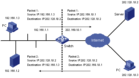
Figure 1-1 Basic NAT procedure
As shown in Figure 1-1, the switch used as a NAT server is located at the joint of an enterprise’s internal network and external networks, and packets are exchanged between an internal PC and an external server as follows:
l When packet 1 sourced from the internal PC with IP address 192.168.1.3 and destined for the external server with IP address 202.120.10.2 arrives at the NAT server, the NAT process checks the packet header. It finds that the packet is destined for an external site and matches a NAT rule. Then the process translates the private IP address (192.168.1.3) in the source address field of the packet header into a public IP address (202.169.10.1), which can be identified on the Internet, and then forwards the packet to its destination and records the private to public address mapping in the NAT table.
l When response packet 2 (with destination address 202.169.10.1) from the external server (202.120.10.2) arrives at the NAT server, the NAT process checks the packet header, looks up the NAT table for the corresponding mapping, and replaces the destination address (202.169.10.1) in the packet header with the private IP address (192.168.1.3) of the internal PC.
The above NAT procedure is transparent to the communicating ends (such as the internal PC and external server in Figure 1-1). The external server thinks that the IP address of the internal PC is 202.169.10.1 and does not know the address 192.168.1.3 at all. In this way, NAT ‘hides’ the enterprise’s internal network.
The advantage of NAT is that it enables internal hosts to access the external network resources with the “privacy” of internal hosts being protected. However, it also has a disadvantage: the packets it processes cannot be encrypted, or else it will not correctly translate the IP address or port for the packets. For example, the encrypted FTP connection cannot be used; otherwise, the FTP port cannot be translated correctly.
1.2 NAT Features
1.2.1 NAT and NAT Control
According to the NAT procedure illustrated in Figure 1-1, when an internal host tries to access an external network, NAT selects a proper public address and substitutes it for the source address in the packets from the internal host. In Figure 1-1, the IP address of the outbound interface on the NAT server is selected. In this case, only one internal host is allowed to access external network at a time because the NAT can provide only one public address. This cannot meet the needs of multiple internal hosts to access external networks concurrently.
To satisfy the concurrent Internet requests from internal hosts, you can have the NAT server owns multiple public IP addresses that can be assigned to internal hosts. When the first internal host tries to access external network, the NAT process selects a public address for it and adds a mapping record in the NAT table; when the second internal host tries to access external network, the NAT process selects another public address, and so on.
& Note:
Since there is little probability that all internal hosts would access external networks at the same time, the public addresses on the NAT server can be much fewer than the internal hosts. You can determine the number of public IP addresses that are needed depending on the statistical number of internal hosts that may access external network at traffic peak.
You can define an address pool for your NAT server to satisfy concurrent Internet requests. In addition, you can use access control list (ACL) to control the NAT:
1) An address pool is a collection of public IP addresses for NAT. You should configure it depending on the number of available public IP addresses, the number of internal hosts, and the practical application. During address translation, the NAT process selects an address from the address pool to substitute the source address.
2) In practice, you may want to allow some internal hosts to access the Internet and inhibit other hosts. You can use an ACL to control the NAT process to allow only some specific hosts to access the Internet. With an ACL, when the NAT process checks the header of a packet, it determines whether the source IP address is allowed to access the Internet, and will not translate the address if it is not allowed.
1.2.2 NAPT
With normal NAT, after the private address of an internal host is mapped to a public address, the public address is unavailable to other internal hosts unless the mapping is removed. This is called one-to-one NAT.
NAPT (network address port translation) is a variation of NAT. It can map multiple internal addresses to the same public address, thus allowing multiple internal hosts to use one public address to access external networks simultaneously. This efficiently saves public addresses.
NAPT mapping involves the mapping of transport layer protocol port number as well as the mapping of IP address. When mapping different internal addresses to the same public address, NAPT maps their port numbers to different port numbers. That is, NAPT implements the translation between <private address + port> and <public address + port>.
NAPT is also known as PAT (port address translation) or address overloading.
The following figure illustrates the fundamentals of NAPT.

Figure 1-2 NAPT address multiplexing
As shown in Figure 1-2, four packets with internal addresses arrive at the switch acting as the NAT server:
l Packets 1 and 2 carry the same internal address but have different source port numbers.
l Packets 3 and 4 carry different internal addresses but have the same source port number.
Through NAPT mapping, the four packets are translated into the packets that carry the same public address but different source port numbers which keeps the four packets being different. So, when the NAT server receives response packets, it can determine which internal hosts the response packets should be forwarded to depending on the destination addresses and port numbers carried in the packets.
1.2.3 Easy IP
The Easy IP feature enables you to associate an ACL directly with the IP address of a VLAN interface that connects to the Internet by using the nat outbound command, so that the NAT translates the source IP addresses of matching packets to this interface address. This feature is useful when only one public IP address (the interface address) is available or there are few internal hosts.
1.2.4 Internal Server
NAT conceals an internal network from the Internet and acts as a shield for internal hosts. But in practical applications, it might be required to allow external hosts to access certain internal devices such as internal WWW servers or FTP servers. By using NAT, you can flexibly add internal servers with public IP addresses so that the servers can be accessed by external hosts. For example, you can:
l Configure public IP address 202.169.10.10 for an internal WWW server.
l Configure public IP address 202.110.10.11 for an internal FTP server.
l Configure public IP address and port number 202.110.10.12:8080 for an internal WWW server.
1.2.5 Special Protocols Supported by NAT
The Comware NAT platform not only implements general NAT features, but also provides complete NAT application-level gateway mechanism, enabling itself to support a variety of special application protocols without any changing on the platform. It has good scalability.
The special protocols supported by NAT include Internet control message protocol (ICMP), domain name system (DNS), Internet locator service (ILS), H.323, FTP, and NetMeeting 3.01.
1.3 Configuring NAT
1.3.1 NAT Configuration Task List
Complete the following tasks to configure NAT:
|
Task |
Remarks |
|
Required |
|
|
Required |
|
|
Required |
|
|
Required |
|
|
Required |
|
|
Optional |
|
|
Optional |
1.3.2 Configuring a NAT Address Pool
A NAT address pool is a set of consecutive public IP addresses. During address translation, the NAT server selects an IP address from the address pool as the translated source address. You can use the nat address-group command to configure an address pool.
Follow these steps to configure a NAT address pool:
|
To do… |
Use the command… |
Remarks |
|
Enter system view |
system-view |
— |
|
Configure a NAT address pool |
nat address-group group-number start-addr end-addr |
Required |
![]() Caution:
Caution:
l A NAT address pool can contain at most 256 IP addresses.
l The IP addresses in a NAT address pool cannot be overlapped with the internal network addresses.
l A NAT address pool cannot contain any subnet or broadcast address.
l You cannot delete an address pool that has been associated with an ACL.
1.3.3 Configuring NAT
By associating an ACL to a NAT address pool (or an interface address), you can make the NAT server perform address translation for packets matching the ACL before forwarding the packets at Layer 3, and directly forward the packets that do not match the ACL without address translation. Before a packet from your internal network is forwarded to any external network, it is first checked against the ACL. If it matches the ACL, the NAT process uses the address pool or the interface address associated with the ACL to translate the packet.
You can use the nat outbound command to associate an ACL with an address pool or interface address. Different NAT modes need different configurations.
I. Configuring one-to-one NAT
Follow these steps to configure one-to-one NAT:
|
To do… |
Use the command… |
Remarks |
|
Enter system view |
system-view |
— |
|
Enter VLAN interface view |
interface Vlan-interface vlan-id |
— |
|
Configure one-to-one NAT |
nat outbound acl-number address-group group-number no-pat slot slot-number |
Required |
The no-pat keyword indicates that only the source IP addresses in packets are translated while the TCP/UDP port numbers remains unchanged. That is, NAT is based on the one-to-one mapping between internal and external IP addresses.
II. Configuring NAPT
Follow these steps to configure NAPT:
|
To do… |
Use the command… |
Remarks |
|
Enter system view |
system-view |
— |
|
Enter VLAN interface view |
interface Vlan-interface vlan-id |
— |
|
Configure NAPT |
nat outbound acl-number address-group group-number slot slot-number |
Required |
Let’s compare the above two tables:
l In the first table, the configuration command uses the no-pat keyword. Only the IP addresses of data packets will be translated while the port numbers remains unchanged, that is, one-to-one NAT is implemented.
l In the second table, the configuration command does not use the no-pat keyword, and so NAPT is enabled. Both IP addresses and port numbers of data packets will be translated, that is, many-to-one NAT is implemented.
![]() Caution:
Caution:
An address pool used for NAPT cannot contain more than three addresses.
III. Configuring the Easy IP feature
You can enable the Easy IP feature by using the nat outbound command without the address-group keyword. After that, when performing address translation, the system will use the IP address of the VLAN interface as the translated source address. The ACL specified in the command can be used to limit the internal addresses allowed for NAT.
Follow these steps to configure the Easy IP feature:
|
To do… |
Use the command… |
Remarks |
|
Enter system view |
system-view |
— |
|
Enter VLAN interface view |
interface Vlan-interface vlan-id |
— |
|
Configure the NAT Easy IP feature |
nat outbound acl-number slot slot-number |
Required |
![]() Caution:
Caution:
l For NAT function, basic ACL (2000 to 2999) supports only source IP address as the filtering item, advanced ACL (3000 to 3999) supports both source IP address and destination IP address as filtering items. Other ACL filtering items are not supported currently.
l After an ACL is configured with the nat outbound command, modifications to the ACL (adding/deleting a rule) are invalid.
l All ACLs configured for a VLAN interface with the nat outbound command can only be configured on the same LPU.
l If multiple ACL rules are configured for a VLAN interface with the nat outbound command, The ACL rules will be matched in the following precedence order: For rules in different ACLs, the rules with larger ACL numbers take precedence over those with smaller ACL numbers. For rules in a same ACL, the rules configured earlier take precedence over those configured later.
1.3.4 Configuring Internal Server
By configuring internal servers with the nat server command, you can map external addresses and ports to internal servers, so as to enable external hosts to access internal servers. When using the nat server command, the information you need to input includes: external address and port, internal address and port of internal server, and protocol type.
Follow these steps to configure internal server(s):
|
To do… |
Use the command… |
Remarks |
|
|
Enter system view |
system-view |
— |
|
|
Enter VLAN interface view |
interface Vlan-interface vlan-id |
— |
|
|
Configure an internal server |
TCP/UDP is used |
nat server protocol pro-type global global-addr global-port inside host-addr host-port slot slot-number |
Perform configuration as required |
|
A protocol other than TCP/UDP is used |
nat server protocol pro-type global global-add inside host-addr slot slot-number |
||
|
Configure a group of consecutive internal servers |
nat server protocol pro-type global global-addr global-port1 global-port2 inside host-addr1 host-addr2 host-port slot slot-number |
||
![]() Caution:
Caution:
l Up to 128 internal servers can be configured in one nat server command.
l Up to 768 nat server commands can be configured for one VLAN interface.
l Up to 4096 internal servers can be configured for one VLAN interface.
l Up to 1024 nat server commands and 4096 internal servers can be configured in the system.
In the above commands, the global-addr and global-port arguments respectively represents the public IP address and service port number provided for external devices to access an internal server; the host-addr and host-port arguments respectively represents the IP address and service port number of the server in the internal network. The global-port and host-port arguments are not needed if a protocol other than TCP and UDP is used which does not use port number.
Note that the host-port argument ranges from 0 to 65,535 and can be replaced by keywords for well-known port numbers. For example, you can use www to replace WWW service port 80, and ftp to replace FTP service port 21. Port number 0 and keyword any have the same meaning: the internal server can provide any available services in the internal network; but this is not supported currently.
& Note:
l If the public IP address you configured for an internal server is the VLAN interface address on the NAT device, you cannot ping through the internal server (which acts as an ICMP server) from the NAT device with the public IP address. However, you can avoid this problem by specifying a source IP address with the -a keyword in the ping command.
l Currently, secondary address translation on a NAT connection is not supported.
l The internal hosts can only access the internal servers through the private IP addresses instead of the public IP addresses of the servers (the public ones are used for external users to access the internal servers).
l To use the NetMeeting software or enable an internal FTP server, you need to configure both the nat server and nat outbound commands. For details, refer to section Configuring NAT.
l For an FTP, TFTP, MSN voice, ILS, or H.323 internal server, besides using the nat server command to configure the translation from an external IP address to its internal IP address, you need to use the nat outbound command to configure the translation from its internal IP address (by referencing an ACL) to the external IP address (by referencing an address pool that contains only the IP address).
1.3.5 Configuring Non-Standard Internal FTP Server
Different from standard internal FTP servers, non-standard internal FTP servers can use extended private ports.
l Standard internal FTP servers can use ports 0 through 12,287 as their public ports, and only port 21 as their private ports.
l Non-standard internal FTP servers can use ports 0 through 12,287 as their public ports (same with standard internal FTP servers), and ports 0 through 65,535 as their private ports.
![]() Caution:
Caution:
Among ports 0 through 65,535, any well-known ports other than port 21 cannot be used as the private ports of non-standard internal FTP servers. (You can see those well-known ports on CLI by command help.)
Follow these steps to configure a non-standard internal FTP server:
|
To do… |
Use the command… |
Remarks |
|
Enter system view |
system-view |
— |
|
Enter VLAN interface view |
interface Vlan-interface vlan-id |
— |
|
Configure a non-standard internal FTP server |
nat ftp server global global-addr global-port inside host-addr host-port slot slot-number |
Required |
1.3.6 Configuring NAT Blacklist
By enabling the NAT blacklist feature and configuring NAT blacklist attributes such as the control threshold for the number of NAT connections and the control threshold for connection setup rate, you can enable the switch to control the number of NAT connections and the connection setup rate.
Follow these steps to configure NAT blacklist attributes:
|
To do… |
Use the command… |
Remarks |
|
Enter system view |
system-view |
— |
|
Enable NAT blacklist for a specified LPU |
nat blacklist start slot slot-number |
Required By default, this feature is disabled. |
|
Set the control mode of NAT blacklist |
nat blacklist mode { all | amount | rate } |
Required |
|
Set the global control threshold for the number of NAT connections per user, or a specific control threshold for the number of NAT connections of a specified user |
nat blacklist limit amount [ source user-ip ] amount-value |
Optional |
|
Set the global or specific control thresholds for connection setup rate |
nat blacklist limit rate [ source ip ] cir cir-value [ cbs cbs-value ebs ebs-value ] |
Optional |
|
Specify the IP address of a user, so as to adopt the specific connection setup rate control thresholds to the user. |
nat blacklist limit rate source user-ip |
Optional |
![]() Caution:
Caution:
l Each command that is used to modify blacklist-related configuration and is not source IP address-specific must be coupled with the reset nat session command.
l Although each blacklist-enabled LPU in the switch independently maintains its own blacklist information, blacklist-related configuration commands executed on the switch apply to all LPUs.
1.3.7 Configuring NAT Connection Aging Time
You can use the nat aging-time command to set the NAT connection aging time for CPU processed ALG (application layer gateway) NAT mapping entries or the NAT connection aging time for network processor (NP) processed NAT mapping entries. A mapping entry is removed from the NAT mapping table when the corresponding aging timer expires.
Follow these steps to configure the aging time of NAT connections:
|
To do… |
Use the command… |
Remarks |
|
Enter system view |
system-view |
— |
|
Configure the aging time of NAT connections |
nat aging-time { alg time-value | np slow } slot slot-number |
Optional By default, the aging time for ALG NAT mapping entries is 120 seconds. An NP uses fast aging timer with aging time of 120 seconds. |
1.3.8 Configuring NAT Security Logging
Security logging is used to record the detailed procedure information of the NAT process.
Security logging will record the following information:
l Source IP address and port number before translation
l Destination IP address and port number before translation
l Source IP address and port number after translation
l Start time and end time of the NAT process
I. Enabling NAT logging
Follow these steps to enable NAT logging:
|
To do… |
Use the command… |
Remarks |
|
Enter system view |
system-view |
— |
|
Enable NAT logging |
ip userlog nat slot slot-number acl acl-number |
Optional By default, this function is disabled. |
II. Setting the wait interval to log active connections
You can use the ip userlog nat active-time command to have the NAT process periodically log an active connection at the set interval after the active time of the connection reaches the set interval.
Follow these steps to set the wait interval to log active connections:
|
To do… |
Use the command… |
Remarks |
|
Enter system view |
system-view |
— |
|
Set the wait interval to log active connections |
ip userlog nat active-time minutes |
Optional By default, the logging of active connections is disabled. |
III. Setting the address and port number of the destination server for log packets
Follow these steps to set the address and port number of the destination server for log packets:
|
To do… |
Use the command… |
Remarks |
|
Enter system view |
system-view |
— |
|
Set the address and port number of the destination server for log packets |
ip userlog nat export [ slot slot-number ] host ip-address udp-port |
Optional By default, ip-address is 0.0.0.0 (which means logging output is disabled) and udp-port is 0. |
If you specify the slot-number argument, the configuration is only effective for the specified LPU; otherwise, the configuration is effective for all LPUs.
IV. Setting the source IP address of log packets
Follow these steps to set the source address of log packets:
|
To do… |
Use the command… |
Remarks |
|
Enter system view |
system-view |
— |
|
Set the source address of log packets |
ip userlog nat export source-ip src-address |
Optional By default, the source IP address of log packets is 0.0.0.0. |
V. Setting the version of log packets
Follow these steps to set the version of log packets:
|
To do… |
Use the command… |
Remarks |
|
Enter system view |
system-view |
— |
|
Set the version of log packets |
ip userlog nat export version version-number |
Optional By default, the version of log packets is version 1. |
VI. Setting NAT logging mode
You can choose one from the following two NAT logging modes:
l Perform logging only when a NAT connection is deleted.
l Perform logging whenever a NAT connection is established or deleted.
Follow these steps to set NAT logging mode:
|
To do… |
Use the command… |
Remarks |
|
Enter system view |
system-view |
— |
|
Configure to perform NAT logging whenever a connection is established |
ip userlog nat mode flow-begin |
Optional By default, NAT logging is performed only when a NAT connection is deleted. |
1.4 Displaying NAT Configuration
|
To do… |
Use the command… |
Remarks |
|
Display NAT address pool configuration |
display nat address-group |
Available in any view |
|
Display the settings of NAT entry aging time for various protocols |
display nat aging-time |
|
|
Display the configurations and status of NAT blacklist |
display nat blacklist { all | ip [ ip-address ] slot slot-number } |
|
|
Display all ACL-NAT address pool associations |
||
|
Display information about all internal servers |
display nat server |
|
|
Display the current NAT statistics |
display nat statistics slot slot-number |
|
|
Display the configuration and statistics of NAT logging |
display ip userlog export slot slot-number |
|
|
Display all information of the current NAT configuration |
display nat all |
|
|
Clear NAT mapping table in memory and NP |
reset nat session slot slot-number |
Available in user view |
1.5 NAT Configuration Example
I. Network requirements
As shown in Figure 1-3:
l An enterprise’s internal network organized by a H3C S3600 switch requires NAT service on a H3C S7506 switch to access the Internet;
l The private IP addresses of the two PCs in internal VLAN 2 are 192.168.1.2 and 192.168.1.3 respectively;
l In the S7506 switch, the LPU implementing NAT is in slot 3;
l There are three valid public IP addresses in the NAT address pool: 200.18.2.3 to 200.18.2.5;
l The interface IP address of VLAN 10 is 200.18.2.2, the subnet mask is 255.255.255.252;
l Static routes have been configured and are available between the subnets.
II. Network diagram
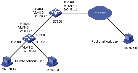
Figure 1-3 Network diagram for NAT
III. Configuration procedure
1) Configure the H3C S3600 switch.
# At the end connecting with the internal users, create VLAN 2 and VLAN-interface 2, and configure the interface IP address.
<H3C> system-view
[H3C] vlan 2
[H3C-vlan2] port ethernet1/0/1 to ethernet1/0/2
[H3C-vlan2] quit
[H3C] interface vlan-interface 2
[H3C-vlan-interface2] ip address 192.168.1.1 255.255.255.0
# At the end connecting with the H3C S7506 switch, create VLAN 3 and VLAN-interface 3, and configure the interface IP address.
[H3C] vlan 3
[H3C-vlan3] port ethernet1/0/24
[H3C-vlan3] quit
[H3C] interface vlan-interface 3
[H3C-vlan-interface3] ip address 192.168.2.1 255.255.255.252
2) Configure the S7506 switch.
# At the end connecting with the H3C S3600 switch, create VLAN 3 and VLAN-interface 3, and configure the interface IP address.
[H3C] vlan 3
[H3C-vlan3] port ethernet4/0/1
[H3C-vlan3] quit
[H3C] interface vlan-interface 3
[H3C-vlan-interface3] ip address 192.168.2.2 255.255.255.252
# At the end connecting with the Internet, create VLAN 10 and VLAN-interface 10, and configure the interface IP address.
[H3C] vlan 10
[H3C-vlan10] port ethernet3/0/1
[H3C-vlan10] quit
[H3C] interface vlan-interface 10
[H3C-vlan-interface10] ip address 200.18.2.2 255.255.255.252
# Configure an ACL rule.
[H3C] acl number 2000
[H3C-acl-basic-2000] rule 0 permit source any
# Configure a NAT address pool with the identifier of 0.
[H3C] nat address-group 0 200.18.2.3 200.18.2.5
# Associate the ACL with the address pool.
[H3C] interface vlan-interface 10
[H3C-vlan-interface10] nat outbound 2000 address-group 0 slot 3
Chapter 2 Netstream Configuration
When configuring Netstream, go to these sections for information you are interested in:
l Displaying Netstream Configuration
l Netstream Configuration Example
& Note:
Currently, the LS81VSNP boards installed in S7500 series switches support the Netstream feature. In this manual, the LS81VSNP board is called LPU.
2.1 Netstream Overview
2.1.1 Introduction to Netstream
Netstream is a traffic statistics feature. It classifies the traffic flow through the switch into different streams according to the source IP address and port number, destination IP address and port number, protocol number and type of service (ToS) in packets, and collects traffic statistics about each stream independently.
Figure 2-1 depicts the basic procedure of Netstream data collection and analysis.
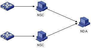
Figure 2-1 Procedure of Netstream data collection and analysis
The procedure is as follows:
1) The switch collects information about each stream and periodically sends the information to a Netstream collector (NSC).
2) The NSC processes the information it received, and then sends the resulting data to the Netstream data analyzer (NDA).
3) The NDA analyzes the data it received, and the analysis result can be used for network charging and deployment.
2.1.2 Implementation of Netstream
With Netstream enabled, a stream entry is first created and saved in the Netstream cache for the system to collect statistics about the stream. Once a preset aging time is reached, the system sends the stream entry in a Netstream export packet (generated by encapsulating the stream entry in a UDP packet) to NSC and deletes (ages) the entry from the Netstream cache.
The aging has two ways:
l Aging by active time: a stream entry is aged out when the active time of the stream (the time elapsed since the stream entry was created) exceeds the corresponding preset time limit.
l Aging by inactive time: a stream entry is aged out when the inactive time of the stream (the time elapsed since the last packet of the stream passed the switch) exceeds the corresponding preset time limit.
Netstream can use three versions of Netstream export packets to send aged stream entries: version 5, version 8 and version 9. But currently, only version 5 and version 9 are configurable:
l If version 5 is configured: the system sends normal stream entries through version 5 packets and sends aggregated stream entries through version 8 packets. (For brevity reason, this will not be mentioned when version 5 is involved in the following text.)
l If version 9 is configured: the system sends all aged stream entries through version 9 packets.
& Note:
If Netstream aggregation is configured, the system classifies and aggregates stream entries into aggregation entries according to configured aggregation rules, and then sends aggregation entries through Netstream export packets.
2.2 Configuring Netstream
2.2.1 Netstream Configuration Task List
Complete the following tasks to configure Netstream:
|
Task |
Remarks |
|
Required |
|
|
Required |
|
|
Optional |
|
|
Configuring the Address Information for Netstream Export Packets |
Optional |
|
Configuring the Version and AS Option for Netstream Export Packets |
Optional |
|
Optional |
|
|
Optional |
|
|
Configuring the Ways to Update the Template for Version 9 Netstream Packets |
Optional |
& Note:
Currently the Netstream and the L3+ traffic accounting functions cannot be enabled simultaneously.
2.2.2 Enabling Netstream
Follow these steps to enable Netstream:
|
To do… |
Use the command… |
Remarks |
|
Enter system view |
system-view |
— |
|
Enable Netstream |
ip netstream inbound source srcslot-number to dstslot-number [ acl acl-number ] Or ip netstream outbound source srcslot-number to dstslot-number |
Required By default, Netstream is disabled. |
![]() Caution:
Caution:
Netstream configuration only applies to the permit rules in the ACL.
2.2.3 Entering Netstream Aggregation View
Use the ip netstream aggregation command to enter a Netstream aggregation view.
The switch supports the following five aggregation modes, each of which corresponds to an aggregation view:
Table 2-1 Aggregation modes of Netstream
|
Mode |
Classify stream entries by… |
|
Autonomous system (AS) aggregation |
Source and destination AS numbers, outbound interface index |
|
Protocol-port aggregation |
Protocol number, source and destination ports |
|
Source-prefix aggregation |
Source AS number, mask length of source address, and source prefix |
|
Destination-prefix aggregation |
Destination AS number, mask length of destination address, destination prefix, and outbound interface index |
|
Source- and destination-prefix aggregation |
Source and destination AS numbers, mask lengths of source and destination addresses, source and destination prefixes, and outbound interface index |
Depending on a selected mode, the system combines multiple stream entries of the same type into one aggregation entry, which corresponds to one aggregation record. The five aggregation modes are independent of each other and can be configured at the same time.
Follow these steps to enter Netstream aggregation view:
|
To do… |
Use the command… |
Remarks |
|
Enter system view |
system-view |
— |
|
Enter Netstream aggregation view |
ip netstream aggregation { as | protocol-port | destination-prefix | prefix | source-prefix } |
Required |
2.2.4 Enabling the Corresponding Aggregation Mode
Perform the following configuration in Netstream aggregation view.
Follow these steps to enable the corresponding aggregation mode:
|
To do… |
Use the command… |
Remarks |
|
Enter system view |
system-view |
— |
|
Enter Netstream aggregation view |
ip netstream aggregation { as | protocol-port | destination-prefix | prefix | source-prefix } |
— |
|
Enable the aggregation mode corresponding to the current aggregation view |
enable |
Optional By default, no aggregation mode is enabled. |
2.2.5 Configuring the Address Information for Netstream Export Packets
After a stream entry is aged out, it is sent to an NSC through Netstream export packet.
Follow these steps to configure the address information of Netstream export packets:
|
To do… |
Use the command… |
Remarks |
|
|
Enter system view |
system-view |
— |
|
|
Configure the IP address and UDP port number of the destination host for Netstream export packets |
Global configuration |
ip netstream export host ip-address udp-port |
Optional By default, l In system view, the destination IP address is 0.0.0.0 and the destination port number is 0. l The IP address and port number of the destination in aggregation view are those configured in system view. |
|
Configuration on a Netstream aggregation view |
ip netstream aggregation { as | protocol-port | destination-prefix | prefix | source-prefix } |
||
|
ip netstream export host ip-address udp-port |
|||
|
Configure the source IP address of Netstream export packets |
Global configuration |
ip netstream export source ip-address |
Optional By default, the source IP address is 0.0.0.0, indicating that the IP address of the outbound interface is used as the source IP address. |
|
Configuration on a Netstream aggregation view |
ip netstream aggregation { as | protocol-port | destination-prefix | prefix | source-prefix } |
||
|
ip netstream export source ip-address |
|||
2.2.6 Configuring the Version and AS Option for Netstream Export Packets
Use the ip netstream export version command to configure the version and the AS option for Netstream export packets. Currently, the switch only supports the configuration of version 5 and version 9.
Both version 5 and 9 packets support the AS options of the border gateway protocol (BGP). You can choose to use original AS numbers (origin-as) or peer AS numbers (peer-as) as the AS numbers for individual IP addresses.
Follow these steps to configure the version and AS option for Netstream export packets:
|
To do… |
Use the command… |
Remarks |
|
Enter system view |
system-view |
— |
|
Configure the version and AS option for Netstream export packets |
ip netstream export version version-number [ origin-as | peer-as ] |
Optional By default, version 5 and AS option peer-as are used for Netstream export packets. |
2.2.7 Configuring the DSCP Value for Netstream Export Packets
Use the ip netstream export dscp command to configure the differentiated services code point (DSCP) value for Netstream export packets. Netstream packets will be classified by their DSCP values.
Follow these steps to configure the DSCP value for Netstream export packets:
|
To do… |
Use the command… |
Remarks |
|
Enter system view |
system-view |
— |
|
Configure the DSCP value for Netstream export packets |
ip netstream export dscp dscp-value |
Optional By default, the DSCP value is 0. |
2.2.8 Configuring Netstream Entry Aging Time
With Netstream enabled, a stream entry is first created and saved in the Netstream cache for the system to collect statistics about a stream. Once a preset aging time is reached, the system sends the statistics of the stream in Netstream export packet to NSC and deletes (ages) the entry from the cache.
The aging has two ways:
l Aging by active time: a stream entry is aged out when the active time of the stream (the time elapsed since the stream entry was created) exceeds the corresponding preset time limit.
l Aging by inactive time: a stream entry is aged out when the inactive time of the stream (the time elapsed since the last packet of the stream passed the switch) exceeds the corresponding preset time limit.
Follow these steps to configure the active/inactive aging time for Netstream entries:
|
To do… |
Use the command… |
Remarks |
|
Enter system view |
system-view |
— |
|
Configure the active aging time for Netstream entries |
ip netstream timeout active minutes |
Optional By default, the active aging time is 30 minutes. |
|
Configure the inactive aging time for Netstream entries |
ip netstream timeout inactive seconds |
Optional By default, the inactive aging time is 60 seconds. |
![]() Caution:
Caution:
The active aging time is configured in minutes, while the inactive aging time is configured in seconds.
2.2.9 Configuring the Ways to Update the Template for Version 9 Netstream Packets
When an NSC receives a Netstream packet of version 9, it identifies the information fields in the packet based on the template carried in the packet. Since the template may change after a period of time, the system needs to update the template on NSC by some way.
The system updates the template on NSC by:
l Number of sent packets: When the number of sent Netstream packets exceeds the threshold set by the ip netstream template refresh command, the system sends the newest template to the NSC.
l Template aging time: When the template aging time (set by the ip netstream template timeout command) expires, the system sends the newest template to the NSC and resets the aging timer.
Follow these steps to configure the ways to update the template for version 9 Netstream packets:
|
To do… |
Use the command… |
Remarks |
|
Enter system view |
system-view |
— |
|
Configure a packet threshold for updating the template of version 9 Netstream packets |
ip netstream template refresh packets |
Optional By default, the packet threshold is 20 packets. |
|
Configure a template aging time for updating the template of version 9 Netstream packets |
ip netstream template timeout minutes |
Optional By default, the template aging time is 30 minutes. |
2.3 Displaying Netstream Configuration
|
To do… |
Use the command… |
Remarks |
|
Display the Netstream configuration and status of the Netstream cache on a specified LPU |
display ip netstream cache slot slot-number |
Available in any view |
|
Display information about Netstream export packets on a specified LPU |
display ip netstream export slot slot-number |
|
|
Clear the Netstream statistics and age all the stream entries in the Netstream cache on a specified LPU |
reset ip netstream statistics slot slot-number |
Available in user view |
2.4 Netstream Configuration Example
I. Network Requirements
Configure Netstream on switch A to collect statistics on received packets. The LPU used to implement Netstream is in slot 5. See Figure 2-2.
II. Network diagram
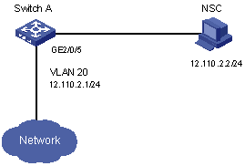
Figure 2-2 Network diagram for Netstream configuration on H3C S7506
III. Configuration procedure
# Enable Netstream on the LPU in slot 5 to collect statistics about the inbound packets on the interface board in slot 3.
<H3C>system-view
[H3C] ip netstream inbound source 3 to 5
# Enable Netstream on the LPU in slot 5 to collect statistics about the inbound packets with source IP address 192.168.0.5 on the interface board in slot 2.
[H3C] acl number 2003
[H3C-acl-basic-2003] rule permit source 192.168.0.5 0
[H3C] ip netstream inbound source 2 to 5 acl 2003
# Configure the source IP address of UDP packets.
[H3C] vlan 20
[H3C-vlan20] port GigabitEthernet2/0/5
[H3C-vlan20] quit
[H3C] interface vlan-interface 20
[H3C-vlan-interface20] ip address 12.110.2.1 24
[H3C-vlan-interface20] quit
[H3C] ip netstream export source 12.110.2.1
# Configure the destination IP address and port number of UDP packets.
[H3C] ip netstream export host 12.110.2.2 9991
# Display the running status of Netstream.
[H3C] display ip netstream cache slot 5
IP netstream cache information in slot 5
Stream active timeout(minute) : 30
Stream inactive timeout(second): 60
Active stream entry : 1
Stream entry been counted : 100
Last statistics reset time : 8/10/2004, 15:42:12
Protocol Total Packets Stream Packets
Streams /Sec /Sec /stream
UDP-other 93 713510 0 43984487
UDP-NetBios 7 0 0 1
Total 100 713510 0 40905573
# Display information about Netstream export packets on the LPU.
[H3C] display ip netstream export slot 5
IP netstream export information in slot 5
IP netstream is enabled in slot : 2
IP netstream is enabled in slot : 3
Version 5 export information
Stream source address : 12.110.2.1
Stream destination IP(UDP) : 12.110.2.2 (9991)
Exported stream number : 103
Exported UDP datagram number(failed number): 102(0)
Chapter 3 Policy Routing Configuration
l Displaying Policy Routing Configuration
l Policy Routing Configuration Example
& Note:
Currently, the LS81VSNP boards installed in S7500 series switches support the policy routing feature. In this manual, the LS81VSNP board is called LPU.
3.1 Overview
Comparing with the normal routing mechanism which determines the next hop of a packet by its destination IP address, policy routing provides a more flexible way to achieve the same purpose. You can perform policy routing configuration so that the device can use not only destination IP address, but also other information carried in packets, such as source IP address, source/destination port number, and even protocol type, to determine the next hops of packets.
On S7500 series switches, policy routing is achieved by redirecting packets. You can use the traffic-redirect commands to redirect the packets that match particular ACLs to specified VLAN interfaces or IP addresses.
3.2 Configuring Policy Routing
Follow these steps to configure policy routing:
|
To do… |
Use the command… |
|
Define an ACL |
acl |
|
Define an ACL rule |
rule |
|
Configure inbound packet redirection |
traffic-redirect inbound ip-group |
|
Configure outbound packet redirection |
traffic-redirect outbound ip-group |
For the configuration of ACL, refer to the ACL module in this manual.
Follow these steps to configure packet redirection:
|
To do… |
Use the command… |
Remarks |
|
|
Enter system view |
system-view |
— |
|
|
Enter VLAN view |
vlan vlan-id |
— |
|
|
Redirect inbound packets matching an ACL or ACL rule on an LPU |
Redirect packets to a specified VLAN interface |
traffic-redirect inbound ip-group { acl-number | acl-name } [ rule rule [ system-index index ] ] interface vlan-interface interface-number [ remark { dscp dscp | { precedence precedence | tos tos}* } ] slot slot-number |
Perform configuration as required. |
|
Redirect packets to a specified IP address |
traffic-redirect inbound ip-group { acl-number | acl-name } [ rule rule [ system-index index ] ] next-hop ipaddr &1-3 [ remark { dscp dscp | { precedence precedence | tos tos}* } ] slot slot-number |
||
|
Redirect outbound packets matching an ACL or ACL rule on an LPU |
Redirect packets to a specified VLAN interface |
traffic-redirect outbound ip-group { acl-number | acl-name } [ rule rule [ system-index index ] ] interface vlan-interface interface-number [ remark { dscp dscp | { precedence precedence | tos tos }*} ] slot slot-number |
|
|
Redirect packets to a specified IP address |
traffic-redirect outbound ip-group { acl-number | acl-name } [ rule rule [ system-index index ] ] next-hop ipaddr &1-3 [ remark { dscp dscp | { precedence precedence | tos tos } *} ] slot slot-number |
||
& Note:
Policy routing configurations only apply to packets that match permit ACL rules.
Refer to related command manual for more information about these commands.
3.3 Displaying Policy Routing Configuration
|
To do… |
Use the command… |
Remarks |
|
Display policy routing configuration |
display qos-vlan [ vlan-id ] traffic-redirect |
Available in any view |
Refer to related command manual for information about the display command.
3.4 Policy Routing Configuration Example
3.4.1 Configuration Example
I. Network requirements
In the network shown in Figure 3-1:
l An LPU is installed in slot 5 of the switch.
l The IP address of Host 1 is 1.0.0.1, and that of Host 2 is 2.0.0.1.
l Set the next hops of packets sourced from Host 1 to 2.0.0.1.
![]() Caution:
Caution:
Make sure the VLAN interfaces of GE2/0/1 and GE2/0/2 are on the same network segments of Host 1 and Host 2 respectively.
II. Network diagram

Figure 3-1 Network diagram for policy routing
III. Configuration procedure
1) Define an ACL for packets source from PC1.
# Create ACL 2000 and enter its view.
<H3C S7500>system-view
[H3C S7500] acl number 2000
# Define a rule to permit packets sourced from Host 1.
[H3C S7500-acl-basic-2000] rule 0 permit source 1.0.0.1 0
[H3C S7500-acl-basic-2000] quit
2) Set the next hop for packets sourced from Host 1.
# Set the next hop of all packets sourced from Host 1 to 2.0.0.1.
[H3C S7500] vlan 2
[H3C S7500-vlan2] traffic-redirect inbound ip-group 2000 rule 0 next-hop 2.0.0.1 slot 5
[H3C S7500-vlan2] quit
# Display information about policy routing configured on VLAN2.
[H3C S7500] display qos-vlan 2 traffic-redirect
Vlan 2 traffic-redirect
Inbound:
Matches: Acl 2000 rule 0 running
Redirected to: next-hop 2.0.0.1 slot 5