- Table of Contents
-
- H3C S7500 Series Operation Manual(Release 3100 Series)-(V1.04)
- 00-1Cover
- 00-2Overview
- 01-CLI Configuration
- 02-Login Configuration
- 03-Configuration File Management Configuration
- 04-VLAN Configuration
- 05-Extended VLAN Application Configuration
- 06-IP Address-IP Performance-IPX Configuration
- 07-GVRP Configuration
- 08-QinQ Configuration
- 09-Port Basic Configuration
- 10-Link Aggregation Configuration
- 11-Port Isolation Configuration
- 12-Port Binding Configuration
- 13-DLDP Configuration
- 14-MAC Address Table Configuration
- 15-MSTP Configuration
- 16-Routing Protocol Configuration
- 17-Multicast Configuration
- 18-802.1x Configuration
- 19-AAA-RADIUS-HWTACACS-EAD Configuration
- 20-Traffic Accounting Configuration
- 21-VRRP-HA Configuration
- 22-ARP Configuration
- 23-DHCP Configuration
- 24-ACL Configuration
- 25-QoS Configuration
- 26-Mirroring Configuration
- 27-Cluster Configuration
- 28-PoE Configuration
- 29-UDP-Helper Configuration
- 30-SNMP-RMON Configuration
- 31-NTP Configuration
- 32-SSH Terminal Service Configuration
- 33-File System Management Configuration
- 34-FTP and TFTP Configuration
- 35-Information Center Configuration
- 36-DNS Configuration
- 37-System Maintenance and Debugging Configuration
- 38-HWPing Configuration
- 39-RRPP Configuration
- 40-NAT-Netstream-Policy Routing Configuration
- 41-Telnet Protection Configuration
- 42-Hardware-Dependent Software Configuration
- Related Documents
-
| Title | Size | Download |
|---|---|---|
| 16-Routing Protocol Configuration | 812 KB |
Table of Contents
Chapter 1 IP Routing Protocol Overview
1.1 Introduction to IP Route and Routing Table
1.2.1 Routing Protocols and Preferences
1.2.2 Traffic Sharing and Route Backup
1.2.3 Routes Shared Between Routing Protocols
Chapter 2 Static Route Configuration
2.1 Introduction to Static Route
2.2 Static Route Configuration
2.2.1 Configuration Prerequisites
2.2.2 Configuring a Static Route
2.3 Displaying the Routing Table
2.4 Static Route Configuration Example
2.5 Troubleshooting a Static Route
3.1.2 RIP Initialization and Running Procedure
3.2 RIP Configuration Task List
3.3.1 Configuration Prerequisites
3.3.2 Configuring Basic RIP Functions
3.4.1 Configuration Prerequisites
3.4.2 Configuring RIP Route Control
3.5 RIP Network Adjustment and Optimization
3.5.1 Configuration Prerequisites
3.6 Displaying and Maintaining RIP Configuration
3.8 Troubleshooting RIP Configuration
4.2 OSPF Configuration Task List
4.3.1 Configuration Prerequisites
4.3.2 Basic OSPF Configuration
4.4 OSPF Area Attribute Configuration
4.4.1 Configuration Prerequisites
4.4.2 Configuring OSPF Area Attributes
4.5 OSPF Network Type Configuration
4.5.1 Configuration Prerequisites
4.5.2 Configuring the Network Type of an OSPF Interface
4.5.3 Setting an NBMA Neighbor
4.5.4 Setting the DR Priority on an OSPF Interface
4.6.1 Configuration Prerequisites
4.6.2 Configuring OSPF Route Summary
4.6.3 Configuring OSPF to Filter Received Routes
4.6.4 Configuring the Cost for Sending Packets on an OSPF Interface
4.6.5 Setting OSPF Route Priority
4.6.6 Configuring OSPF to Redistribute Routes
4.7 OSPF Network Adjustment and Optimization
4.7.1 Configuration Prerequisites
4.7.3 Configuring the LSA transmission delay
4.7.4 Configuring the SPF Calculation Interval
4.7.5 Disabling OSPF Packet Transmission on an Interface
4.7.6 Configuring OSPF Authentication
4.7.7 Configuring to Fill the MTU Field When an Interface Transmits DD Packets
4.7.8 Configuring OSPF Network Management System (NMS)
4.8 Displaying and Maintaining OSPF Configuration
4.9 OSPF Configuration Example
4.9.1 Configuring DR Election Based on OSPF Priority
4.9.2 Configuring OSPF Virtual Link
4.10 Troubleshooting OSPF Configuration
5.2 IS-IS Configuration Task List
5.3.3 Enabling IS-IS on the Specified Interface
5.3.4 Configuring DIS Priority
5.3.6 Configuring the Line Type of an Interface
5.3.7 Configuring Route Redistribution
5.3.8 Configuring Route Filtering
5.3.9 Configuring Route Leaking
5.3.10 Configuring Route Summarization
5.3.11 Configuring Default Route Generation
5.3.12 Configuring Protocol Priority
5.3.13 Configuring a Cost Style
5.3.14 Configuring Interface Cost
5.3.15 Configuring IS-IS Timer
5.3.16 Configuring Authentication
5.3.17 Adding an Interface to a Mesh Group
5.3.18 Configuring Overload Tag
5.3.19 Configuring to Discard LSPs with Incorrect Checksum
5.3.20 Configuring to Log Peer Changes
5.3.21 Assigning an LSP Refresh Time
5.3.22 Assigning an LSP Maximum Aging Time
5.3.23 Configuring SPF Parameters
5.3.24 Enabling/Disabling Packet Transmission Through an Interface
5.3.25 Resetting all IS-IS Configuration Data
5.3.26 Resetting Configuration Data of an IS-IS Peer
5.4 Displaying and Maintaining Integrated IS-IS Configuration
5.5 Integrated IS-IS Configuration Example
6.2 BGP Configuration Task List
6.3.1 Configuration Prerequisites
6.3.2 Configuring Basic BGP Functions
6.4 Configuring the Way to Advertise/Receive Routing Information
6.4.1 Configuration Prerequisites
6.4.3 Configuring BGP Route Aggregation
6.4.4 Enabling Default Route Advertising
6.4.5 Configuring the BGP Route Advertising Policy
6.4.6 Configuring BGP Route Receiving Policy
6.4.7 Configuring BGP-IGP Route Synchronization
6.4.8 Configuring BGP Route Dampening
6.4.9 Configuring BGP Load Balance
6.5 Configuring BGP Route Attributes
6.6 Adjusting and Optimizing a BGP Network
6.6.1 Configuration Prerequisites
6.6.2 Adjusting and Optimizing a BGP Network
6.7 Configuring a Large-Scale BGP Network
6.7.1 Configuration Prerequisites
6.7.2 Configuring a BGP Peer Group
6.7.3 Configuring a BGP Community
6.7.5 Configuring BGP Confederation
6.8 Displaying and Maintaining BGP Configuration
6.8.1 Displaying BGP Configuration
6.8.3 Clearing BGP Information
6.9 BGP Configuration Examples
6.9.1 Configuring BGP AS Confederation Attribute
6.10 Troubleshooting BGP Configuration
Chapter 7 IP Routing Policy Configuration
7.1 IP Routing Policy Overview
7.1.2 Applications of Routing Policy
7.2 IP Routing Policy Configuration
7.2.1 Configuring a Route Policy
7.2.2 Define an IP Prefix List
7.2.3 Configuring an AS Path List
7.2.4 Configuring a Community List
7.2.5 Applying a Routing Policy to Import Routes
7.2.6 Applying a Routing Policy to Receive or Advertise Routes
7.3 Displaying and Maintaining IP Routing Policy Configuration
7.4 IP Routing Policy Configuration Example
7.4.1 Filtering Routing Information
7.5 Troubleshooting IP Routing Policy
Chapter 8 Route Capacity Configuration
8.1.2 Route Capacity Limitation on the S7500 Series
8.2 Route Capacity Configuration
8.2.1 Setting the Lower Limit and the Safety Value of the Switch Memory
8.2.2 Enabling/Disabling Automatic Protocol Connection Recovery
8.3 Displaying and Maintaining Route Capacity Configuration
Chapter 1 IP Routing Protocol Overview
Go to these sections for information you are interested in:
l Introduction to IP Route and Routing Table
& Note:
When running a routing protocol, the Ethernet switch also functions as a router. The term “router” in this document refers to a router in a generic sense or an Ethernet switch running routing protocols.
1.1 Introduction to IP Route and Routing Table
1.1.1 IP Route
Routers are used for route selection on the Internet. As a router receives a packet, it selects an appropriate route (through a network) according to the destination address of the packet and forwards the packet to the next router. The last router on the route is responsible for delivering the packet to the destination host.
1.1.2 Routing Table
The key for a router to forward packets is the routing table. Each router maintains a routing table. Each entry in this table contains an IP address that represents a host/subnet and specifies which physical port on the router should be used to forward the packets destined for the host/subnet. And the router forwards those packets through this port to the next router or directly to the destination host if the host is on a network directly connected to the router.
Each entry in a routing table contains:
l Destination address: It identifies the address of the destination host or network of an IP packet.
l Network mask: Along with the destination address, it identifies the address of the network segment where the destination host or router resides. By performing “logical AND” between destination address and network mask, you can get the address of the network segment where the destination host or router resides. For example, if the destination address is 129.102.8.10 and the mask is 255.255.0.0, the address of the network segment where the destination host or router resides is 129.102.0.0. A mask consists of some consecutive 1s, represented either in dotted decimal notation or by the number of the consecutive 1s in the mask.
l Output interface: It indicates through which interface IP packets should be forwarded to reach the destination.
l Next hop address: It indicates the next router that IP packets will pass through to reach the destination.
l Preference of the route added to the IP routing table: There may be multiple routes with different next hops to the same destination. These routes may be discovered by different routing protocols, or be manually configured static routes. The one with the highest preference (the smallest numerical value) will be selected as the current optimal route.
According to different destinations, routes fall into the following categories:
l Subnet route: The destination is a subnet.
l Host route: The destination is a host.
In addition, according to whether the network where the destination resides is directly connected to the router, routes falls into the following categories:
l Direct route: The router is directly connected to the network where the destination resides.
l Indirect route: The router is not directly connected to the network where the destination resides.
In order to avoid an oversized routing table, you can set a default route. All the packets for which the router fails to find a matching entry in the routing table will be forwarded through this default route.
Figure 1-1 shows a relatively complicated internet environment, the number in each network cloud indicate the network address. Router G is connected to three networks, and so it has three IP addresses and three physical ports. Its routing table is shown in Figure 1-1.

|
Destination Network |
Nexthop |
Interface |
|
11.0.0.0 |
14.0.0.1 |
3 |
|
12.0.0.0 |
14.0.0.1 |
3 |
|
13.0.0.0 |
16.0.0.1 |
2 |
|
14.0.0.0 |
14.0.0.3 |
3 |
|
15.0.0.0 |
17.0.0.2 |
1 |
|
16.0.0.0 |
16.0.0.2 |
2 |
|
17.0.0.0 |
17.0.0.1 |
1 |
1.2 Routing Management Policy
On an S7500 switch, you can manually configure a static route to a certain destination, or configure a dynamic routing protocol to make the switch interact with other routers in the internetwork and find routes. On an S7500 switch, the static routes configured by the user and the dynamic routes discovered by routing protocols are managed uniformly. The static routes and the routes learned or configured by different routing protocols can also be shared among routing protocols.
1.2.1 Routing Protocols and Preferences
Different routing protocols may discover different routes to the same destination, but only one route among these routes and the static routes is optimal. In fact, at any given moment, only one routing protocol can determine the current route to a specific destination. Routing protocols (including static routing) are assigned different preferences. When there are multiple routing information sources, the route discovered by the routing protocol with the highest preference will become the current route. Routing protocols and their default route preferences (the smaller the value is, the higher the preference is) are shown in Table 1-1.
In the table, “0” is used for directly connected routes, and “255” is used for routes from untrusted source.
Table 1-1 Routing protocols and corresponding route preferences
|
Routing protocol or type |
Preference of the corresponding route |
|
DIRECT |
0 |
|
OSPF |
10 |
|
IS-IS |
15 |
|
STATIC |
60 |
|
RIP |
100 |
|
OSPF ASE |
150 |
|
OSPF NSSA |
150 |
|
UNKNOWN |
255 |
|
IBGP |
256 |
|
EBGP |
256 |
Except for direct routing, you can manually configure the preferences of various dynamic routing protocols as required. In addition, you can configure different preferences for different static routes.
1.2.2 Traffic Sharing and Route Backup
I. Traffic sharing
The S7500 series support multi-route mode, allowing the configuration of multiple routes that reach the same destination and have the same preference. The same destination can be reached via multiple different routes, whose preferences are equal. When there is no route with a higher preference to the same destination, all these routes will be adopted. Then, the packets destined for that same destination will be forwarded through these routes in turn to implement traffic sharing.
II. Route backup
The S7500 series support route backup. When the primary route fails, the system automatically switches to a backup route to improve network reliability.
To achieve route backup, you can configure multiple routes to the same destination according to actual situation. One of these routes has the highest preference and is called primary route. The other routes have descending preferences and are called backup routes. Normally, the router sends data through the primary route. When line failure occurs on the primary route, the primary route will hide itself and the router will choose the one whose preference is the highest among the remaining backup routes as the path to send data. In this way, the switchover from the primary route to a backup route is implemented. When the primary route recovers, the router will restore it and re-select a route. And, as the primary route has the highest preference, the router will choose the primary route to send data. This process is the automatic switchover from the backup route to the primary route.
1.2.3 Routes Shared Between Routing Protocols
As the algorithms of various routing protocols are different, different routing protocols may discover different routes. This brings about the problem of how to share the discovered routes between routing protocols. The S7500 series can import (with the import-route command) the routes discovered by one routing protocol to another routing protocol. Each protocol has its own route redistribution mechanism. For detailed information, refer to the description of importing external routes in routing protocol configuration of the following chapters
Chapter 2 Static Route Configuration
When configuring static routes, go to these sections for information you are interested in:
l Introduction to Static Route
l Displaying the Routing Table
l Static Route Configuration Example
l Troubleshooting a Static Route
2.1 Introduction to Static Route
2.1.1 Static Route
Static routes are special routes. They are manually configured by the administrator. By configuring static routes, you can build an interconnecting network. The problem for such configuration is that a static route cannot change automatically to steer away from the fault point without the help of the administrator when a fault occurs on the network.
In a relatively simple network, you only need to configure static routes to make routers work normally. Proper configuration and usage of static routes can improve network performance and ensure sufficient bandwidth for important applications.
Static routes are divided into three types:
l Destination reachable route: normal route. If a static route to a destination belongs to this type, the IP packets sent to this destination will be forwarded to the next hop. It is the most common type of static routes.
l Destination unreachable route: If a static route to a destination has the "reject" attribute, all the IP packets sent to this destination will be discarded, and the source hosts will be informed of the unreachability of the destination.
l Blackhole route: If a static route to a destination has the “blackhole” attribute, the outgoing interface of this route is the Null 0 interface regardless of the next hop address, and all the IP packets sent to this destination will be dropped without notifying the source hosts.
The attributes "reject" and "blackhole" are usually used to limit the range of the destinations that this router can reach, and help troubleshoot the network.
2.1.2 Default Route
A default route is a special route. You can manually configure a static route as the default route. Some dynamic routing protocols, such as OSPF and IS-IS, can automatically generate a default route.
A default route is a route used only when no matching entry is found in the routing table. That is, the default route is used only when there is no proper route. In a routing table, both the destination IP address and mask of the default route are 0.0.0.0. You can use the display ip routing-table command to view whether the default route has been set. If the destination address of a packet does not match any entry in the routing table, the router will select the default route for the packet; in this case, if there is no default route, the packet will be discarded, and an Internet control message protocol (ICMP) packet will be returned to inform the source host that the destination host or network is unreachable.
2.2 Static Route Configuration
2.2.1 Configuration Prerequisites
Before configuring a static route, perform the following tasks:
l Configuring the physical parameters of the related interface
l Configuring the link layer attributes of the related interface
l Configuring an IP address for the related interface
2.2.2 Configuring a Static Route
Follow these steps to configure a static route:
|
To do... |
Use the command... |
Remarks |
|
Enter system view |
system-view |
— |
|
Add a static route |
ip route-static ip-address { mask | mask-length } { interface-type interface-number | next-hop } [ preference value ] [ reject | blackhole ] |
Required By default, the system can obtain the route to the subnet directly connected to the router. |
|
Delete all static routes |
delete static-routes all |
Optional This command can delete all static routes, including the default route. |
|
Configure the default preference for static routes |
ip route-static default-preference default-preference-value |
Optional By default, the preference value is 60. |
& Note:
l If the destination IP address and the mask of a route are both 0.0.0.0, the route is the default route. Any packet for which the router fails to find a matching entry in the routing table will be forwarded through the default route.
l Do not configure the next hop address of a static route as the IP address of an interface on the local switch.
l The preference can be configured differently to implement flexible route management policy.
2.3 Displaying the Routing Table
|
To do... |
Use the command... |
Remarks |
|
Display routing table summary |
display ip routing-table |
Available in any view |
|
Display routing table details |
display ip routing-table verbose |
|
|
Display the detailed information of a specific route |
display ip routing-table ip-address [ mask ] [ longer-match ] [ verbose ] |
|
|
Display the routes in a specified address range |
display ip routing-table ip-address1 mask1 ip-address2 mask2 [ verbose ] |
|
|
Display the routes fount after specified ACL filtering |
display ip routing-table acl acl-number [ verbose ] |
|
|
Display the routes found after specified prefix list filtering |
display ip routing-table ip-prefix ip-prefix-name [ verbose ] |
|
|
Display the routes discovered by a specified protocol |
display ip routing-table protocol protocol [ inactive | verbose ] |
|
|
Display the tree-structured routing table information |
display ip routing-table radix |
|
|
Display the statistics of the routing table |
display ip routing-table statistics |
2.4 Static Route Configuration Example
I. Network requirements
It is required that all the hosts/Layer 3 switches in the figure can interconnect with each other by configuring static routes.
II. Network diagram
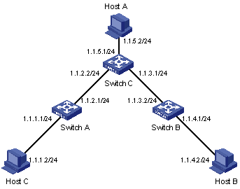
Figure 2-1 Static route configuration
III. Configuration procedure
& Note:
Before the following configuration, make sure that the Ethernet link layer works normally and the IP addresses of the VLAN interfaces have been configured correctly.
# Configure static routes on Switch A.
[SwitchA] ip route-static 1.1.3.0 255.255.255.0 1.1.2.2
[SwitchA] ip route-static 1.1.4.0 255.255.255.0 1.1.2.2
[SwitchA] ip route-static 1.1.5.0 255.255.255.0 1.1.2.2
# Configure static routes on Switch B.
[SwitchB] ip route-static 1.1.2.0 255.255.255.0 1.1.3.1
[SwitchB] ip route-static 1.1.5.0 255.255.255.0 1.1.3.1
[SwitchB] ip route-static 1.1.1.0 255.255.255.0 1.1.3.1
# Configure static routes on Switch C.
[SwitchC] ip route-static 1.1.1.0 255.255.255.0 1.1.2.1
[SwitchC] ip route-static 1.1.4.0 255.255.255.0 1.1.3.2
# Configure the default gateway of Host A to 1.1.5.1. Detailed configuration procedure is omitted.
# Configure the default gateway of Host B to 1.1.4.1. Detailed configuration procedure is omitted.
# Configure the default gateway of Host C to 1.1.1.1. Detailed configuration procedure is omitted.
Now, all the hosts/switches in the figure can interconnect with each other.
2.5 Troubleshooting a Static Route
Symptom: The switch is not configured with a dynamic routing protocol. Both the physical status and the link layer protocol status of an interface are UP, but IP packets cannot be normally forwarded on the interface.
Solution: Perform the following procedure.
Use the display ip routing-table protocol static command to check that the corresponding static route is correctly configured.
Use the display ip routing-table command to check that the static route is valid.
Chapter 3 RIP Configuration
When configuring RIP, go to these sections for information you are interested in:
l Displaying and Maintaining RIP Configuration
l Troubleshooting RIP Configuration
3.1 RIP Overview
Routing Information Protocol (RIP) is a simple Interior Gateway Protocol (IGP), mainly used in small-sized networks.
3.1.1 RIP Working Mechanism
I. Basic concept of RIP
RIP is a distance-vector (D-V) algorithm-based protocol. It exchanges routing information via UDP packets.
RIP uses hop count (also called routing cost) to measure the distance to a destination address. In RIP, the hop count from a router to its directly connected network is 0, and that to a network which can be reached through another router is 1, and so on. To limit convergence time, RIP prescribes that the cost is an integer ranging from 0 and 15. A cost value of 16 (or bigger) is considered infinite, which means the destination network or host is unreachable.
To improve performance and avoid routing loop, RIP supports split horizon. Besides, RIP can import routes from other routing protocols.
II. RIP routing table
Each router running RIP manages a routing table, which contains routing entries to all the reachable destinations. Each routing entry contains:
l Destination address: IP address of a host or network.
l Next hop address: IP address of an interface on the adjacent router that IP packets should pass through to reach the destination.
l Interface: Interface on this router, through which IP packets should be forwarded to reach the destination.
l Cost: Cost from the local router to the destination.
l Routing time: Time elapsed since the routing entry was last updated. The time is reset to 0 whenever the routing entry is updated.
l Route tag: Identifies whether a route is of internal routing protocol or external routing protocol.
III. RIP timers
As defined in RFC 1058, RIP employs three timers: Period update, Timeout, and Garbage-collection.
l Period update timer: This timer is used to periodically trigger routing information update so that the router can send all RIP routes to all the neighbors.
l Timeout timer: If a RIP route is not updated (that is, the switch does not receive any routing update from the neighbor) within the timeout time of this timer, the route is considered unreachable.
l Garbage-collection timer: An unreachable route will be completely deleted from the routing table if no update for the route is received from the neighbor before this timer times out.
3.1.2 RIP Initialization and Running Procedure
The RIP initialization and running procedure is described as follow:
l Once RIP is enabled on a router, the router broadcasts or multicasts requests to its neighbors. Upon receiving the packet, each neighbor running RIP returns responses containing its routing table information.
l When this router receives the responses, it updates its local routing table and sends triggered updates to the neighbor. Upon receiving the triggered updates, the neighbor sends the triggered updates to all its neighbors. After a series of update triggering processes, each router can get and keep the updated routing information.
l By default, RIP sends its routing table information to its neighbors every 30 seconds. Upon receiving the packets, the neighbors maintain their own routing tables and select optimal routes, and then advertise update information to their respective neighbors so as to make the updated routes known globally. Furthermore, RIP uses the timeout mechanism to handle the timeout routes so as to ensure real-time and valid routes.
RIP is commonly used by most IP router suppliers. It can be used in most campus networks and the regional networks that are simple and less dispersive. For larger and more complicated networks, RIP is not recommended.
3.2 RIP Configuration Task List
Complete the following tasks to configure RIP:
|
Task |
Remarks |
|
|
Required |
||
|
Optional |
||
|
Optional |
||
|
Optional |
||
|
Optional |
||
|
Optional |
||
|
Optional |
||
|
Optional |
||
|
Optional |
||
|
Optional |
||
|
Optional |
||
|
Optional |
||
|
Optional |
||
|
Optional |
||
|
Optional |
||
3.3 Basic RIP Configuration
3.3.1 Configuration Prerequisites
Before configuring basic RIP functions, perform the following tasks:
l Configuring the link layer protocol
l Configuring IP address on each interface, and make sure that all adjacent nodes are reachable with each other
3.3.2 Configuring Basic RIP Functions
I. Enable RIP and specify networks
Follow these steps to enable RIP globally and on the interface of a specified network segment:
|
To do... |
Use the command... |
Remarks |
|
Enter system view |
system-view |
— |
|
Enable RIP globally and enter RIP view |
rip |
— |
|
Enable RIP on the interface of a specified network segment |
network network-address |
Required By default, RIP is disabled on any interface. |
& Note:
l If you make some RIP configurations in interface view before enabling RIP, those configurations will take effect after RIP is enabled.
l RIP runs only on the interfaces residing on the specified networks. Therefore, you need specify the network after enabling RIP to validate RIP on a specific interface.
II. Set the RIP operating status on an interface
Follow these steps to set the RIP operating status on an interface:
|
To do... |
Use the command... |
Remarks |
|
Enter system view |
system-view |
— |
|
Enter interface view |
interface interface-type interface-number |
— |
|
Enable an interface to receive RIP routing updates |
rip input |
Optional By default, all the interfaces are allowed to send and receive RIP packets. |
|
Enable the interface to send RIP routing updates |
rip output |
|
|
Enable the interface to send and receive RIP packets |
rip work |
III. Specify the RIP version on an interface
Follow these steps to specify the RIP version on an interface:
|
To do... |
Use the command... |
Remarks |
|
Enter system view |
system-view |
— |
|
Enter interface view |
interface interface-type interface-number |
— |
|
Specify RIP version on the interface |
rip version { 1 | 2 [ broadcast | multicast ] } |
Required By default, the interface can receive RIP-1 and RIP-2 broadcast packets but send only RIP-1 packets. When specifying the RIP version on an interface to RIP-2, you can also specify the mode (broadcast or multicast) to send RIP packets. |
3.4 RIP Route Control
In actual implementation, it may be needed to control RIP routing information more accurately to accommodate complex network environments. By performing the configuration described in the following sections, you can:
l Control route selection by adjusting additional routing metrics on interfaces running RIP.
l Reduce the size of the routing table by setting route summary and disabling the receiving of host routes.
l Filter the received routes.
l Set the preference of RIP to change the preference order of routing protocols. This order makes sense when more than one route to the same destination is discovered by multiple routing protocols.
l Import external routes in an environment with multiple routing protocols and filter the advertised routes.
3.4.1 Configuration Prerequisites
Before configuring RIP route control, perform the following tasks:
l Configuring IP address on each interface, and make sure that all adjacent nodes are reachable with each other
l Configuring basic RIP functions
3.4.2 Configuring RIP Route Control
I. Set the additional routing metrics of an interface
Additional routing metric is the routing metric (hop count) added to the original metrics of RIP routes on an interface. It does not change the metric value of a RIP route in the routing table, but will be added for incoming or outgoing RIP routes on the interface.
Follow these steps to set additional routing metric:
|
To do... |
Use the command... |
Remarks |
|
Enter system view |
system-view |
— |
|
Enter interface view |
interface interface-type interface-number |
— |
|
Set the additional routing metric to be added for incoming RIP routes on the interface |
rip metricin value |
Optional By default, the additional routing metric added for incoming routes on an interface is 0. |
|
Set the additional routing metric to be added for outgoing RIP routes on the interface |
rip metricout value |
Optional By default, the additional routing metric added for outgoing routes on an interface is 1. |
& Note:
The rip metricout command takes effect only on the RIP routes learnt by the router and the RIP routes generated by the router itself, but not on any route imported to RIP from other routing protocols.
II. Configure RIP route summarization
Route summarization means that different subnet routes in a natural network segment can be summarized into one route with a natural mask for transmission to another network segment. This function is used to reduce the routing traffic on the network as well as to reduce the size of the routing table.
Route summarization does not work for RIP-1. RIP-2 supports route summarization. When it is needed to advertise all subnet routes, you can disable the function for RIP-2.
Follow these steps to configure RIP route summarization:
|
To do... |
Use the command... |
Remarks |
|
Enter system view |
system-view |
— |
|
Enter RIP view |
rip |
— |
|
Enable RIP-2 automatic route summarization |
summary |
Required By default, RIP-2 automatic route summarization is enabled. |
III. Disable the receiving of host routes
In some special cases, the router can receive a lot of host routes from the same network segment, and these routes are of little help in route addressing but consume a large amount of network resources. After host route receiving is disabled, a router can refuse any incoming host routes.
Follow these steps to disable the receiving of host routes:
|
To do... |
Use the command... |
Remarks |
|
Enter system view |
system-view |
— |
|
Enter RIP view |
rip |
— |
|
Disable the receiving of host routes |
undo host-route |
Required By default, the router receives host routes. |
IV. Configure inbound/outbound route filtering policies
Route filtering is supported by the router. You can filter received or advertised routes by configuring the inbound and outbound route filtering policies via referencing an ACL and IP prefix list. You can also specify to receive only routes from a specified neighbor.
Follow these steps to configure the filtering of incoming/outgoing routes:
|
To do... |
Use the command... |
Remarks |
|
Enter system view |
system-view |
— |
|
Enter RIP view |
rip |
— |
|
Configure to filter incoming routes |
filter-policy { acl-number | [ ip-prefix ip-prefix-name ] [ gateway ip-prefix-name ] } import [ interface interface-type interface-number ] |
Optional By default, RIP does not filter any incoming routes. The gateway keyword is used to filter the incoming routes advertised from a specified address. |
|
filter-policy route-policy route-policy-name import |
||
|
Configure to filter outgoing routes |
filter-policy { acl-number | ip-prefix ip-prefix-name } export [ protocol | interface interface-type interface-number ] |
Optional By default, RIP does not filter any outgoing routes. |
|
filter-policy route-policy route-policy-name export |
& Note:
l The filter-policy import command filters the RIP routes received from neighbors, and the routes being filtered out will neither be added to the routing table nor be advertised to any neighbors.
l The filter-policy export command filters all the routes to be advertised, including the routes imported by using the import-route command as well as RIP routes learnt from neighbors.
l The filter-policy export command without the routing-protocol argument filters all the routes to be advertised, including the routes imported by the import-route command.
V. Set RIP preference
Follow these steps to set RIP preference:
|
To do... |
Use the command... |
Remarks |
|
Enter system view |
system-view |
— |
|
Enter RIP view |
rip |
— |
|
Set the RIP preference |
preference value |
Required The default RIP preference is 100. |
VI. Enable RIP traffic sharing
Follow these steps to enable RIP traffic sharing:
|
To do... |
Use the command... |
Remarks |
|
Enter system view |
system-view |
— |
|
Enter RIP view |
rip |
— |
|
Enable traffic sharing |
traffic-share-across-interface |
Required By default, traffic-share-across-interface is disabled |
VII. Configure RIP route redistribution
Follow these steps to configure RIP route redistribution:
|
To do... |
Use the command... |
Remarks |
|
Enter system view |
system-view |
— |
|
Enter RIP view |
rip |
— |
|
Set the default cost for RIP to redistribute routes from other protocols |
default cost value |
Optional When you use the import-route command without specifying the cost of imported routes, the default cost you set here will be used. |
|
Configure RIP to redistribute routes from another protocol |
import-route protocol [ process-id | allow-ibgp ] [ cost value | route-policy route-policy-name ]* |
Optional |
& Note:
Use the keyword allow-ibgp with care when redistributing routes from BGP, because it redistributes IBGP routes without keeping the AS_PATH attribute, which may lead to routing loops between ASs.
3.5 RIP Network Adjustment and Optimization
In some special network environments, some RIP features need to be configured and RIP network performance needs to be adjusted and optimized. By performing the configuration mentioned in this section, the following can be implemented:
l Changing the convergence speed of RIP network by adjusting RIP timers
l Avoiding routing loop by configuring split horizon
l Packet validation in network environments with high security requirements
l Configuring RIP feature on an interface or link with special requirements
3.5.1 Configuration Prerequisites
Before adjusting RIP, perform the following tasks:
l Configuring IP address on each interface, and make sure that all adjacent nodes are reachable with each other
l Configuring basic RIP functions
3.5.2 Configuration Tasks
I. Configure RIP timers
Follow these steps to configure RIP timers:
|
To do... |
Use the command... |
Remarks |
|
Enter system view |
system-view |
— |
|
Enter RIP view |
rip |
— |
|
Set the values of RIP timers |
timers { update update-timer | timeout timeout-timer } * |
Required By default, Update timer value is 30 seconds and Timeout timer value is 180 seconds. |
& Note:
When configuring the values of RIP timers, you should take network performance into consideration and perform consistent configuration on all routers running RIP to avoid unnecessary network traffic and network route oscillation.
II. Configure split horizon
Follow these steps to configure split horizon:
|
To do... |
Use the command... |
Remarks |
|
Enter system view |
system-view |
— |
|
Enter interface view |
interface interface-type interface-number |
— |
|
Enable split horizon |
rip split-horizon |
Required By default, an interface uses split horizon to send RIP packets. |
& Note:
Disabling the split horizon function on a point-to-point link does not take effect.
III. Configure RIP-1 packet zero field check
Follow these steps to configure RIP-1 packet zero field check:
|
To do... |
Use the command... |
Remarks |
|
Enter system view |
system-view |
— |
|
Enter RIP view |
rip |
— |
|
Enable zero field check of RIP-1 packets |
checkzero |
Required By default, zero field check is performed on RIP-1 packets. |
& Note:
Some fields in a RIP-1 packet must be 0, and they are known as zero fields. For RIP-1, zero field check is performed on incoming packets, those RIP-1 packets with nonzero value in a zero filed will not be processed further. As a RIP-2 packet has no zero fields, this configuration is invalid for RIP-2.
IV. Set RIP-2 packet authentication mode
RIP-2 supports two authentication modes, simple authentication and MD5 authentication.
Simple authentication cannot provide complete security, because the authentication keys sent along with packets are not encrypted. Therefore, simple authentication cannot meet high security needs.
Follow these steps to set RIP-2 packet authentication mode:
|
To do... |
Use the command... |
Remarks |
|
Enter system view |
system-view |
— |
|
Enter interface view |
interface interface-type interface-number |
— |
|
Set RIP-2 packet authentication mode |
rip authentication-mode { simple password | md5 { rfc2453 key-string | rfc2082 key-string key-id } } |
Required If you specify to use MD5 authentication, you must specify one of the following MD5 authentication types: rfc2453 (this type supports the packet format defined in RFC 2453) rfc2082 (this type supports the packet format defined in RFC 2082) |
V. Configure a RIP neighbor
Follow these steps to configure a RIP neighbor:
|
To do... |
Use the command... |
Remarks |
|
Enter system view |
system-view |
— |
|
Enter RIP view |
rip |
— |
|
Configure a RIP neighbor |
peer ip-address |
Required To make RIP works on a link that does not support broadcast/multicast packets, you must manually configure the RIP neighbor. Normally, RIP uses broadcast or multicast addresses to send packets. |
3.6 Displaying and Maintaining RIP Configuration
|
To do... |
Use the command... |
Remarks |
|
Display the current RIP running status and configuration information |
display rip |
Available in any view |
|
Display RIP routing information |
display rip routing |
|
|
Reset the system configuration related to RIP |
reset |
Available in RIP view |
3.7 RIP Configuration Example
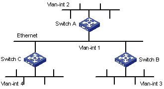
I. Network requirements
As shown in Figure 3-1, Switch C is connected to subnet 117.102.0.0 through an Ethernet port. Switch A and Switch B are connected to networks 155.10.1.0 and 196.38.165.0 respectively through Ethernet ports. Switch C, Switch A and Switch B are interconnected through Ethernet 110.11.2.0. It is required to configure RIP correctly to ensure the interworking between the networks connected to Switch C, Switch A and Switch B.
II. Network diagram
|
Device |
Interface |
IP address |
Device |
Interface |
IP address |
|
Switch A |
Vlan-int1 |
110.11.2.1/24 |
Switch B |
Vlan-int1 |
110.11.2.2/24 |
|
|
Vlan-int2 |
155.10.1.1/24 |
|
Vlan-int3 |
196.38.165.1/24 |
|
Switch C |
Vlan-int1 |
110.11.2.3/24 |
|
|
|
|
|
Vlan-int4 |
117.102.0.1/16 |
|
|
|
III. Configuration procedure
& Note:
Only the configuration related to RIP is listed below. Before the following configuration, make sure the Ethernet link layer works normally and the IP addresses of VLAN interfaces are configured correctly.
1) Configure Switch A
# Configure RIP.
<SwitchA>system-view
[SwitchA] rip
[SwitchA-rip] network 110.11.2.0
[SwitchA-rip] network 155.10.1.0
2) Configure Switch B
# Configure RIP.
<SwitchB>system-view
[SwitchB] rip
[SwitchB-rip] network 196.38.165.0
[SwitchB-rip] network 110.11.2.0
3) Configure Switch C
# Configure RIP.
<SwitchC>system-view
[SwitchC] rip
[SwitchC-rip] network 117.102.0.0
[SwitchC-rip] network 110.11.2.0
3.8 Troubleshooting RIP Configuration
Symptom: The switch cannot receive any RIP update when the physical connection between the switch and the peer routing device is normal.
Solution: RIP is not enabled on the corresponding interface (for example, the undo rip work command is executed on the interface) or RIP is not enabled by the network command on the interface. The peer routing device is configured to work in multicast mode (for example, the rip version 2 multicast command is executed) but the multicast mode is not configured on the corresponding interface of the switch.
Chapter 4 OSPF Configuration
When configuring OSPF, go to these sections for information you are interested in:
l OSPF Configuration Task List
l Displaying and Maintaining OSPF Configuration
l Troubleshooting OSPF Configuration
4.1 OSPF Overview
4.1.1 Introduction to OSPF
Open Shortest Path First (OSPF) is a link state interior gateway protocol developed by IETF. At present, OSPF version 2 (RFC 2328) is used, which has the following features:
l High applicability: OSPF supports networks of various sizes and can support up to several hundred routers.
l Fast convergence: OSPF can transmit update packets instantly after network topology changes for routing information synchronization in the autonomous system (AS).
l Loop-free: OSPF computes routes with the Shortest Path Tree algorithm according to the collected link states, so no loop routes are generated from the algorithm itself.
l Area partition: OSPF allows an autonomous system network to be divided into different areas for ease of management so that routing information transmitted between the areas is abstracted further, thereby reducing network bandwidth consumption.
l Equivalent route: OSPF supports multiple equivalent routes to the same destination.
l Routing hierarchy: OSPF has a four-level routing hierarchy. It prioritizes the routes as intra-area, inter-area, external type-1, and external type-2 routes.
l Authentication: OSPF supports interface-based packet authentication to guarantee the security of route calculation.
l Multicast transmission: OSPF supports transmitting protocol packets in multicast mode.
4.1.2 OSPF Route Calculation
The following is a simple process of how OSPF calculates routes when there is no area partition:
l Each OSPF router maintains a link state database (LSDB), which describes the topology of the whole AS. Based on the network topology around itself, each router generates link state advertisements (LSAs) and sends them to other routers in update packets. The LSAs a router receives from other routers form the LSDB of the router.
l An LSA describes the network topology around a router, whereas an LSDB describes the network topology of the whole network. Routers can easily transform the LSDB to a weighted and directed map, which reflects the topology of the whole network. All routers have the same map.
l Each router uses the shortest path first (SPF) algorithm to calculate the shortest path tree that shows the routes to the nodes in the autonomous system. The router itself is the root of the tree. External routes are leaf nodes, which are marked by the routers from which they are advertised to record information outside the AS. Each router maintains a different routing table.
Furthermore, to enable individual routers to broadcast their local status information (such as information about available interface and reachable neighbor) to the whole AS, routers in the AS must establish adjacencies among them. In this case, a route change on any router will result in multiple transmissions, which are unnecessary and bandwidth consuming. To solve this problem, designated router (DR) and backup designated router (BDR) are defined in OSPF. For details about DR and BDR, see section 4.1.4 III. "DR and BDR".
OSPF supports interface-based packet authentication to guarantee the security of route calculation. In addition, it transmits and receives packets in multicast (224.0.0.5 and 224.0.0.6).
4.1.3 Basic OSPF Concepts
I. Router ID
To run OSPF, a router must have a router ID. A router ID can be configured manually. If no router ID is configured, the system will automatically select an IP address from the IP addresses of the interfaces as the router ID. A router ID is selected in the following way: if loopback interface addresses are configured, the system chooses the latest configured IP address as the router ID; if no loopback interface is configured, the first configured IP address among the IP addresses of other interfaces will be the router ID.
II. DR and BDR
For details, see section 4.1.4 III. "DR and BDR".
III. Area
If all the routers on an ever-growing huge network run OSPF, the large number of routers will result in an enormous LSDB, which will consume an enormous storage space, complicate the running of SPF algorithm, and increase CPU load. Furthermore, as a network grows larger, it is more potential to have changes in the network topology. Hence, the network will often be in “turbulence”, and a great number of OSPF packets will be generated and transmitted in the network. This will lower the network bandwidth utilization. In addition, each change will cause all the routers on the network to recalculate routing information.
OSPF solves the above-mentioned problems by dividing an AS into multiple areas. Areas group routers logically. A router on the border of an area belongs to more than one area. A router connecting the backbone area to a non-backbone area is called an area border router (ABR). An ABR can connect to the backbone area physically or logically.
Area partition in OSPF reduces the number of LSAs in the network and enhances OSPF scalability. To further reduce routing table size and the number of LSAs in some non-backbone areas on the edge of an AS, you can configure these areas as stub areas.
A stub area cannot import any external routes. For this reason the concept NSSA area (not-so-stubby area) is introduced. In an NSSA area, type 7 LSAs are allowed to be propagated. A type 7 LSA is generated by an ASBR (autonomous system boundary router) in a NSSA area. A type 7 LSA reaching an ABR in the NSSA area is transformed into an AS-external LSA, which is then advertised to other areas.
IV. Backbone area and virtual link
l Backbone Area
In OSPF area partition, not all areas are parallel. One area, whose area ID is 0, is different from all the other areas. This area is called the backbone area.
l Virtual link
Since all areas must be connected to the backbone area, the concept virtual link is introduced to maintain logical connectivity between the backbone area and any other areas physically separated from the backbone area.
V. Route summary
After an AS is divided into different areas that are interconnected through OSPF ABRs, the routing information between areas can be reduced through route summary. This reduces the size of routing tables and improves the calculation speed of routers.
After an ABR in an area calculates the intra-area routes in the area, the ABR aggregates multiple OSPF routes into one LSA (based on the summary configuration) and sends the LSA outside the area.
For example, in Figure 4-1, there are three intra-area routes in Area 19: 19.1.1.0/24, 19.1.2.0/24, and 19.1.3.0/24. If route summary is configured, the three routes are aggregated into one route 19.1.0.0/16, and only one corresponding LSA, which describes the route after summary, is generated on RTA.

Figure 4-1 Area partition and route aggregation
4.1.4 OSPF Network Types
I. Four OSPF network types
OSPF divides networks into four types by link layer protocols:
l Broadcast: If Ethernet or FDDI is adopted, OSPF defaults the network type to broadcast. In a broadcast network, protocol packets are sent in multicast (224.0.0.5 and 224.0.0.6) by default.
l Non-broadcast multi-access (NBMA): If Frame Relay, ATM, or X.25 is adopted, OSPF defaults the network type to NBMA. In an NBMA network, protocol packets are sent in unicast.
l Point-to-multipoint (P2MP): OSPF will not default the network type of any link layer protocol to P2MP. A P2MP network must be compulsorily changed from another network type. The common practice is to change an NBMA network into a P2MP network. In a P2MP network, protocol packets are sent in multicast (224.0.0.5).
l Point-to-point (P2P): If PPP or HDLC is adopted, OSPF defaults the network type to P2P. In a P2P network, protocol packets are sent in multicast (224.0.0.5).
II. Principles for configuring an NBMA network
An NBMA network is a non-broadcast and multi-accessible network. ATM and frame relay networks are typical NBMA networks.
Some special configurations need to be done on an NBMA network. In an NBMA network, an OSPF router cannot discover an adjacent router by broadcasting Hello packets. Therefore, you must manually specify an IP address for the adjacent router and specify whether the adjacent router can vote for a DR.
An NBMA network must be fully connected. That is, any two routers in the network must be directly reachable to each other through a virtual circuit. If two routers in the network are not directly reachable to each other, you must configure the corresponding interface type to P2MP. If a router in the network has only one peer, you can change the corresponding interface type to P2P.
The differences between NBMA and P2MP are as follows:
l An NBMA network is fully connected, non-broadcast, and multi-accessible, whereas a P2MP network is not necessarily fully connected.
l DR and BDR must be elected on an NBMA network, while on a P2MP network there are no such routers.
l NBMA is a default network type. A P2MP network, however, must be compulsorily changed from another network type. The most common practice is to change an NBMA network into a P2MP network.
l NBMA sends protocol packets in unicast and neighbors must be configured manually, while P2MP sends protocol packets in multicast.
III. DR and BDR
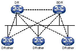
In a broadcast network or an NBMA network, routing information needs to be transmitted between any two routers. If there are n routers in the network, n x (n-1)/2 adjacencies must be established. In this case, any route change on any router will result in multiple transmissions, which waste bandwidth. To solve this problem, DR is defined in OSPF so that all routers send information to the DR only and the DR broadcasts the network link states in the network.
If the DR fails, a new DR must be elected and synchronized with the other routers in the network. The process will take quite a long time and in the process, route calculation is incorrect. To shorten the process, BDR is introduced in OSPF.
A BDR provides backup for a DR. DR and BDR are elected at the same time. Adjacencies are also established between the BDR and all the other routers on the segment, and routing information is also exchanged between them. Once the DR fails, the BDR becomes the DR immediately. This is because no re-election is needed and the adjacencies already exist. Now, a new BDR needs to be elected. This process will also take quite a long time, but it will not affect route calculation.
With DR and BDR, routers other than DR and BDR (called DR Others) needs not build adjacencies between them, nor will they exchange routing information. This reduces the number of adjacencies among routers on the broadcast or NBMA network.
In Figure 4-2, the solid lines represent physical Ethernet connections and the dotted lines represent adjacencies established. The figure shows that, with the DR/BDR mechanism adopted, seven adjacencies suffice for the five routers.
IV. DR/BDR election
Instead of being manually configured, DR and BDR are elected by all the routers on the current network segment. The priority of a router interface determines the qualification of the interface in DR/BDR election. All the routers with DR priorities greater than 0 on the current network segment are eligible "candidates".
Hello packets serve as the "votes" in the election. Each router writes the DR it selects into the Hello packet and sends the packet to each router running OSPF on the network segment. If two routers on the same network segment declare themselves to be the DR, the one with the highest DR priority will be preferred. If their priorities are the same, the one with greater router ID will be preferred. A router whose DR priority is 0 can neither be elected as the DR nor be elected as the BDR.
Note the following points:
l DR election is required for broadcast or NBMA interfaces but is not required for P2P or P2MP interfaces.
l DR is based on the router interfaces in a certain segment. A router may be a DR on one interface and a BDR or DR Other on another interface.
l If a new router is added after DR and BDR election, the router does not become the DR immediately even if it has the highest DR priority.
l The DR on a network segment is not necessarily the router with the highest priority. Likewise, the BDR is not necessarily the router with the second-highest priority.
4.1.5 OSPF Packets
OSPF uses five types of packets:
l Hello packet
Hello packets are most commonly used OSPF packets, which are periodically sent by a router to its neighbors. A Hello packet contains the values of some timers, the DR, the BDR and the known peers.
l DD packet
When two routers synchronize their databases, they use database description (DD) packets to describe their own LSDBs, which contain the digest of each LSA. The digest refers to the HEAD of an LSA which uniquely identifies the LSA. This reduces the size of traffic transmitted between the routers because the HEAD of an LSA only occupies a small portion of the LSA. With the HEAD, the peer router can judge whether it has the LSA or not.
l LSR packet
After exchanging DD packets, the two routers know which LSAs of the peer router are lacking in the local LSDB. They then send link state request (LSR) packets to the peer requesting for the lacking LSAs. These LSR packets contain the digest of the needed LSAs.
l LSU packet
Link state update (LSU) packets are used to transmit the needed LSAs to the peer router. An LSU packet is a collection of multiple LSAs (complete LSAs, not LSA digest).
l LSAck packet
Link state acknowledgment (LSAck) packets are used to acknowledge received LSU packets. An LSAck contains the HEAD(s) of LSA(s) to be acknowledged (one LSAck packet can acknowledge multiple LSAs).
4.1.6 LSA Types
I. Five basic LSA types
As described in the preceding sections, LSAs are the primary source for OSPF to calculate and maintain routes. RFC 2328 defines five types of LSAs:
l Router-LSA: Type-1 LSAs, generated by every router to describe the router's link states and costs, and advertised only in the area where the router resides.
l Network-LSA: Type-2 LSAs, generated by the DRs of broadcast or NBMA networks to describe the link states of the current network segment and are advertised only in the area where the DRs reside.
l Summary-LSA: Type-3 and Type-4 LSAs, generated by ABRs and advertised in the areas associated with the LSAs. Each Summary-LSA describes a route to a destination in another area of the AS (also called inter-area route). Type-3 Summary-LSAs are for routes to networks (that is, their destinations are segments), while Type-4 Summary-LSAs are for routes to ASBRs.
l AS-external-LSA: Type-5 LSA, also called ASE LSA, generated by ASBRs to describe the routes to other ASs and advertised to the whole AS (excluding stub areas). The default AS route can also be described by AS-external-LSAs.
II. Type-7 LSAs
In RFC 1587 (OSPF NSSA Option), Type-7 LSA, a new LSA type, is added.
As described in RFC 1587, Type-7 LSAs and Type-5 LSAs mainly differ in the following two ways:
l Type-7 LSAs are generated and advertised in an NSSA, where Type-5 LSAs will not be generated or advertised.
l Type-7 LSAs can only be advertised in an NSSA area. When Type-7 LSAs reach an ABR, the ABR can convert part of the routing information carried in the Type-7 LSAs into Type-5 LSAs and advertise the Type-5 LSAs. Type-7 LSAs are not directly advertised to other areas (including the backbone area).
4.1.7 OSPF Features
S7500 series support the following OSPF features:
l Stub area: Stub area is defined to reduce the cost for the routers in the area to receive ASE routes.
l NSSA area: NSSA area is defined to remove the limit on the topology in a stub area.
l OSPF multi-process: Multiple OSPF processes can run on a router.
l Sharing discovered routing information with other dynamic routing protocols: At present, OSPF supports importing the routes of other dynamic routing protocols (such as RIP), and static routes as OSPF external routes into the AS to which the router belongs. In addition, OSPF supports advertising the routing information it discovered to other routing protocols.
l Authentication key: OSPF supports the authentication of the packets between neighboring routers in the same area by using one of the two methods: plain text authentication key and MD5 authentication key.
l Flexible configuration of router interface parameters: For a router interface, you can configure the following OSPF parameters: output cost, Hello interval, retransmission interval, interface transmission delay, route priority, dead time for a neighboring router, and packet authentication mode and authentication key.
l Virtual link: Virtual links can be configured.
4.2 OSPF Configuration Task List
Complete the following tasks to configure OSPF:
|
Task |
Remarks |
|
|
Required |
||
|
Optional |
||
|
Optional |
||
|
Optional |
||
|
Optional |
||
|
Optional |
||
|
Optional |
||
|
Configuring the Cost for Sending Packets on an OSPF Interface |
Optional |
|
|
Optional |
||
|
Optional |
||
|
Optional |
||
|
Optional |
||
|
Optional |
||
|
Optional |
||
|
Optional |
||
|
Configuring to Fill the MTU Field When an Interface Transmits DD Packets |
Optional |
|
|
Optional |
||
4.3 Basic OSPF Configuration
Before you can configure other OSPF features, you must first enable OSPF and specify the interface and area ID.
4.3.1 Configuration Prerequisites
Before configuring OSPF, perform the following tasks:
l Configuring the link layer protocol
l Configuring the network layer addresses of interfaces so that adjacent nodes are reachable to each other at the network layer
4.3.2 Basic OSPF Configuration
Basic OSPF configuration includes:
l Configuring router ID
To ensure stable OSPF operation, you should determine the division of router IDs and manually configure them when implementing network planning. When you configure router IDs manually, make sure each router ID is uniquely used by one router in the AS. A common practice is to set the router ID as the IP address of an interface on the router.
l Enabling OSPF
S7500 Series Ethernet Switches support multiple OSPF processes. To enable multiple OSPF processes on a router, you need to specify different process IDs. OSPF process ID is only locally significant; it does not affect the packet exchange between an OSPF process and other routers. Therefore, packets can be exchanged between routers with different OSPF processes IDs.
l Configuring an area and the network segments in the area. You need to plan areas in an AS before performing the corresponding configurations on each router.
When configuring the routers in the same area, you should consider the area as the basis to complete most configurations uniformly. Wrong configuration may disable information transmission between neighboring routers and even lead to congestion or self-loop of routing information.
Follow these steps to perform basic OSPF configuration:
|
To do... |
Use the command... |
Remarks |
|
Enter system view |
system-view |
— |
|
Disable protocol multicast MAC address delivery |
undo protocol multicast-mac enable |
Optional |
|
Configure the router ID |
router id router-id |
Optional If multiple OSPF processes run on a router, you are recommended to use the router-id keyword in the ospf [ process-id [ router-id router-id ] ] command to specify different router IDs for different processes. |
|
Enable OSPF and enter OSPF view |
ospf [ process-id [ router-id router-id ] ] |
— Enter OSPF view. |
|
Enter OSPF area view |
area area-id |
— |
|
Configure the network segments in the area |
network address wildcard-mask |
Required By default, an interface does not belong to any area. |
& Note:
l The undo protocol multicast-mac enable command must be configured if Layer 2/Layer 3 multicast function is enabled in the system.
l In router ID selection, the priorities of the router IDs configured with the ospf [ process-id [ router-id router-id ] ] command, the router id command, and the priorities of the router IDs automatically selected are in a descending order.
l Router IDs can be re-selected. A re-selected router ID takes effect only after the OSPF process is restarted.
l The ospf [ process-id [ router-id router-id ] ] command is recommended for configuring router IDs manually.
l The ID of an OSPF process is unique.
l A segment can belong to one area only and you must specify each OSPF interface to belong to a particular area.
4.4 OSPF Area Attribute Configuration
Area partition in OSPF reduces the number of LSAs in the network and enhances OSPF scalability. To further reduce routing table size and the number of LSAs in some non-backbone areas on the edge of the AS, you can configure these areas as stub areas.
A stub area cannot import any external route. For this reason the concept of NSSA area is introduced. Type7 LSAs can be advertised in an NSSA area. Type7 LSAs are generated by ASBRs of the NSSA area, and will be transformed into AS-external LSAs whey reaching ABRs in the NSSA area, which will then be advertised to other areas.
After area partition, the OSPF route updates between non-backbone areas are exchanged by way of the backbone area. Therefore, OSPF requires that all the non-backbone areas should keep connectivity with the backbone area and the backbone area must keep connectivity in itself.
If the physical connectivity cannot be ensured due to various restrictions, you can configure OSPF virtual links to satisfy this requirement.
4.4.1 Configuration Prerequisites
Before configuring OSPF area attributes, perform the following tasks:
l Configuring the network layer addresses of interfaces so that the adjacent nodes are reachable to each other at the network layer
l Performing basic OSPF configuration
4.4.2 Configuring OSPF Area Attributes
Follow these steps to configure OSPF area attributes:
|
To do... |
Use the command... |
Remarks |
|
Enter system view |
system-view |
— |
|
Enter OSPF view |
ospf [ process-id [ router-id router-id ] ] |
— |
|
Enter OSPF area view |
area area-id |
— |
|
Configure the current area to be a stub area |
stub [ no-summary ] |
Optional By default, no area is configured as a stub area. |
|
Configure an area to be an NSSA area |
nssa [ default-route-advertise | no-import-route | no-summary ]* |
Optional By default, no area is configured as an NSSA area. |
|
Configure the cost of the default route transmitted by OSPF to a stub or NSSA area |
default-cost cost |
Optional This can be configured on an ABR only. By default, the cost of the default route to a stub or NSSA area is 1. |
|
Create and configure a virtual link |
vlink-peer router-id [ hello seconds | retransmit seconds | trans-delay seconds | dead seconds | simple password | md5 keyid key ]* |
Optional For a virtual link to take effect, you need to use this command at both ends of the virtual link and ensure consistent configurations of the hello, dead, and other parameters at both ends. |
& Note:
l You must use the stub command on all the routers connected to a stub area to configure the area with the stub attribute.
l You must use the nssa command on all the routers connected to an NSSA area to configure the area with the NSSA attribute.
4.5 OSPF Network Type Configuration
OSPF divides networks into four types by link layer protocol. See section 4.1.4 "OSPF Network Types". An NBMA network must be fully connected. That is, any two routers in the network must be directly reachable to each other through a virtual circuit. However, in many cases, this cannot be implemented and you need to use a command to change the network type forcibly.
Configure the interface type as P2MP if not all the routers are directly accessible on an NBMA network. Change the interface type to P2P if the router has only one peer on the NBMA network.
In addition, when configuring a broadcast network or NBMA network, you can also specify DR priority for each interface to control the DR/BDR selection in the network. Thus, the router with higher performance and reliability can be selected as a DR or BDR.
4.5.1 Configuration Prerequisites
Before configuring the network type of an OSPF interface, perform the following tasks:
l Configuring the network layer address of the interface so that adjacent nodes are reachable at network layer
l Performing basic OSPF configuration
4.5.2 Configuring the Network Type of an OSPF Interface
Follow these steps to configure the network type of an OSPF interface:
|
To do... |
Use the command... |
Remarks |
|
Enter system view |
system-view |
— |
|
Enter interface view |
interface interface-type interface-number |
— |
|
Configure the network type of the OSPF interface |
ospf network-type { broadcast | nbma | p2mp | p2p } |
Required By default, the network type of an interface depends on the physical interface. |
& Note:
l After an interface has been configured with a new network type, the original network type of the interface is removed automatically.
l Note that, neighboring relationship can be established between two interfaces configured as broadcast, NBMA, or P2MP only if the interfaces are on the same network segment.
4.5.3 Setting an NBMA Neighbor
Some special configurations need to be done on an NBMA network. Since an NBMA interface cannot discover the adjacent router by broadcasting Hello packets, you must manually specify the IP address of the adjacent router for the interface and specify whether the adjacent router has the right to vote.
Follow these steps to set an NBMA neighbor:
|
To do... |
Use the command... |
Remarks |
|
Enter system view |
system-view |
— |
|
Enter OSPF view |
ospf [ process-id [ router-id router-id ] ] |
— |
|
Set an NBMA neighbor |
peer ip-address [ dr-priority dr-priority ] |
Required By default, the priority for the neighbor of an NBMA interface is 1. |
4.5.4 Setting the DR Priority on an OSPF Interface
You can control the DR/BDR election on a broadcast or NBMA network by configuring the DR priorities of interfaces.
Follow these steps to set the DR priority on an OSPF interface:
|
To do... |
Use the command... |
Remarks |
|
Enter system view |
system-view |
— |
|
Enter interface view |
interface interface-type interface-number |
— |
|
Set the DR priority on the OSPF interface |
ospf dr-priority value |
Required The default DR priority is 1. |
& Note:
The DR priorities configured by the ospf dr-priority command and the peer command have different purpose:
l The priority set with the ospf dr-priority command is used for actual DR election.
l The priority set with the peer command is used to indicate if a neighbor has the right to vote. If you specify the priority to 0 when configuring a neighbor, the local router will believe that the neighbor has no right to vote and sends no Hello packet to it. This configuration can reduce the number of Hello packets on the network during the election of DR and BDR. However, if the local router is already a DR or BDR, it will send Hello packets to the neighbor whose DR priority is 0 to establish the neighboring relationship.
4.6 OSPF Route Control
Perform the following configurations to control the advertisement and reception of the routing information discovered by OSPF and import routing information discovered by other protocols.
4.6.1 Configuration Prerequisites
Before configuring OSPF route control, perform the following tasks:
l Configuring the network layer addresses of interfaces so that the adjacent nodes are reachable to each other at the network layer
l Completing basic OSPF configuration
l Configuring filter list to filter routing information
4.6.2 Configuring OSPF Route Summary
The configuration of OSPF route summary includes:
l Configuring ABR route summary
l Configuring ASBR route summary for imported routes
Follow these steps to configure ABR route summary:
|
To do... |
Use the command... |
Remarks |
|
Enter system view |
system-view |
— |
|
Enter OSPF view |
ospf [ process-id [ router-id router-id ] ] |
— |
|
Enter area view |
area area-id |
— |
|
Enable ABR route summary |
abr-summary ip-address mask [ advertise | not-advertise ] |
Required This command takes effect only when it is configured on an ABR. By default, this function is disabled on an ABR. |
Follow these steps to configure ASBR route summary:
|
To do... |
Use the command... |
Remarks |
|
Enter system view |
system-view |
— |
|
Enter OSPF view |
ospf [ process-id [ router-id router-id ] ] |
— |
|
Enable ASBR route summary |
asbr-summary ip-address mask [ not-advertise | tag value ] |
Required This command takes effect only when it is configured on an ASBR. By default, summary of imported routes is disabled. |
4.6.3 Configuring OSPF to Filter Received Routes
Follow these steps to configure OSPF to filter received routes:
|
To do... |
Use the command... |
Remarks |
|
Enter system view |
system-view |
— |
|
Enter OSPF view |
ospf [ process-id [ router-id router-id ] ] |
— |
|
Configure to filter the received routes |
filter-policy { acl-number | ip-prefix ip-prefix-name | gateway ip-prefix-name } import |
Required By default, OSPF does not filter received routing information. |
& Note:
OSPF is a dynamic routing protocol based on link state, with routing information hidden in LSAs. Therefore, OSPF cannot filter any advertised or received LSA. In fact, the filter-policy import command filters the routes calculated by OSPF; only the routes passing the filter can be added to the routing table.
4.6.4 Configuring the Cost for Sending Packets on an OSPF Interface
Follow these steps to configure the cost for sending packets on an OSPF interface:
|
To do... |
Use the command... |
Remarks |
|
Enter system view |
system-view |
— |
|
Enter interface view |
interface interface-type interface-number |
— |
|
Configure the cost for sending packets on an OSPF interface |
ospf cost value |
Required By default, OSPF calculates the cost for sending packets on an interface according to the current baud rate on the interface. For a VLAN interface on the switch, this value is fixed at 1. |
4.6.5 Setting OSPF Route Priority
Since multiple dynamic routing protocols may be running on one router, the problem of route sharing and selection between various routing protocols arises. The system sets a priority for each routing protocol (which you can change manually), and when more than one route to the same destination is discovered by different protocols, the route with the highest priority will take preference over other routes.
Follow these steps to set OSPF route priority:
|
To do... |
Use the command... |
Remarks |
|
Enter system view |
system-view |
— |
|
Enter OSPF view |
ospf [ process-id [ router-id router-id ] ] |
— |
|
Set OSPF route priority |
preference [ ase ] value |
Required By default, the OSPF route priority is 10 and the priority of OSPF ASE is 150. |
4.6.6 Configuring OSPF to Redistribute Routes
Follow these steps to configure OSPF to redistribute routes:
& Note:
l The import-route command cannot import the default route. To import the default route, you must use the default-route-advertise command.
l The filtering of advertised routes by OSPF means that OSPF only converts the external routes meeting the filter criteria into Type-5 or Type-7 LSAs and advertises them.
l When enabling OSPF to redistribute routes, you can also configure the defaults of some additional parameters, such as cost, number of routes, tag, and type. A route tag can be used to identify protocol-related information.
l Use the keyword allow-ibgp with care when redistributing routes from BGP, because it redistributes IBGP routes without keeping the AS_PATH attribute, which may lead to routing loops between ASs.
4.7 OSPF Network Adjustment and Optimization
You can adjust and optimize an OSPF network in the following aspects:
l By changing the OSPF packet timers, you can adjust the convergence speed of the OSPF network and the network load brought by OSPF packets. On some low-speed links, you need to consider the delay experienced when the interfaces transmit LSAs.
l By adjusting SPF calculation interval, you can mitigate resource consumption caused by frequent network changes.
l In a network with high security requirements, you can enable OSPF authentication to enhance OSPF network security.
l In addition, OSPF supports network management. You can configure the binding of the OSPF MIB with an OSPF process and configure the Trap message transmission and logging functions.
4.7.1 Configuration Prerequisites
Before adjusting and optimizing an OSPF network, perform the following tasks:
l Configuring the network layer addresses of interfaces so that the adjacent nodes are reachable to each other at the network layer
l Configuring basic OSPF functions
4.7.2 Configuring OSPF Timers
The Hello intervals for OSPF neighbors must be consistent. The value of Hello interval is in inverse proportion to route convergence speed and network load.
The dead time on an interface must be at least four times of the Hello interval on the same interface.
After a router sends an LSA to a neighbor, it waits for an acknowledgement packet from the neighbor. If the router receives no acknowledgement packet from the neighbor within the retransmission interval, it retransmits the LSA to the neighbor.
Follow these steps to configure OSPF timers:
|
To do... |
Use the command... |
Remarks |
|
Enter system view |
system-view |
— |
|
Enter interface view |
interface interface-type interface-number |
— |
|
Set the hello interval on the interface |
ospf timer hello seconds |
Optional By default, p2p and broadcast interfaces send Hello packets every 10 seconds; while p2mp and NBMA interfaces send Hello packets every 30 seconds. |
|
Set the poll interval on the NBMA interface |
ospf timer poll seconds |
Optional By default, poll packets are sent every 120 seconds. |
|
Set the dead time of the neighboring router on the interface |
ospf timer dead seconds |
Optional By default, the dead time for the OSPF neighboring router on a p2p or broadcast interface is 40 seconds and that for the OSPF neighboring router on a p2mp or NBMA interface is 120 seconds. |
|
Set the interval at which the router retransmits an LSA to the neighboring router on the interface |
ospf timer retransmit interval |
Optional 5 seconds by default. |
& Note:
Do not set an LSA retransmission interval that is too short. Otherwise, unnecessary retransmission will occur. LSA retransmission interval must be greater than the round trip time of a packet between two routers.
4.7.3 Configuring the LSA transmission delay
Follow these steps to configure the LSA transmission delay:
|
To do... |
Use the command... |
Remarks |
|
Enter system view |
system-view |
— |
|
Enter interface view |
interface interface-type interface-number |
— |
|
Configure the LSA transmission delay |
ospf trans-delay seconds |
Required 1 second by default |
& Note:
The transmission of OSPF packets on a link also takes time. Therefore, a transmission delay should be added to the aging time of LSAs before the LSAs are transmitted. For a low-speed link, pay close attention to this configuration.
4.7.4 Configuring the SPF Calculation Interval
Whenever the LSDB of OSPF is changed, the shortest paths need to be recalculated. When the network changes frequently, calculating the shortest paths immediately after LSDB changes will consume enormous resources and affect the operation efficiency of the router. By adjusting the minimum SPF calculation interval, you can lighten the negative effects caused by frequent network changes.
Follow these steps to set the SPF calculation interval:
|
To do... |
Use the command... |
Remarks |
|
Enter system view |
system-view |
— |
|
Enter OSPF view |
ospf [ process-id [ router-id router-id ] ] |
— |
|
Set the SPF calculation interval |
spf-schedule-interval interval |
Required 5 seconds by default |
4.7.5 Disabling OSPF Packet Transmission on an Interface
To prevent OSPF routing information from being acquired by the routers on a certain network, use the silent-interface command to disable OSPF packet transmission on the corresponding interface.
Follow these steps to disable OSPF packet transmission through an interface:
|
To do... |
Use the command... |
Remarks |
|
Enter system view |
system-view |
— |
|
Enter OSPF view |
ospf [ process-id [ router-id router-id ] ] |
— |
|
Disable OSPF packet transmission on a specified interface |
silent-interface silent-interface-type silent-interface-number |
Required By default, all the interfaces are allowed to transmit OSPF packets. |
& Note:
l On the same interface, you can disable multiple OSPF processes from transmitting OSPF packets. The silent-interface command, however, only applies to the OSPF interface where the specified process has been enabled, without affecting the interface for any other process.
l After an OSPF interface is set to be in silent status, the interface can still advertise its direct route. However, the Hello packets from the interface will be blocked, and no neighboring relationship can be established on the interface. This enhances OSPF networking adaptability, thus reducing the consumption of system resources.
4.7.6 Configuring OSPF Authentication
Follow these steps to configure OSPF authentication:
|
To do... |
Use the command... |
Remarks |
|
Enter system view |
system-view |
— |
|
Enter OSPF view |
ospf [ process-id [ router-id router-id ] ] |
— |
|
Enter OSPF area view |
area area-id |
— |
|
Configure the authentication mode of the OSPF area |
authentication-mode { simple | md5 } |
Required By default, no authentication mode is configured for an area. |
|
Return to OSPF view |
quit |
— |
|
Return to system view |
quit |
— |
|
Enter interface view |
interface interface-type interface-number |
— |
|
Configure the authentication mode of the OSPF interface |
ospf authentication-mode { simple password | md5 key-id key } |
Required By default, OSPF packets are not authenticated on an interface. |
& Note:
l OSPF supports packet authentication and receives only those packets that are successfully authenticated. If packet authentication fails, no neighboring relationship will be established.
l The authentication modes for all routers in an area must be consistent. The authentication passwords for all routers on a network segment must also be consistent.
4.7.7 Configuring to Fill the MTU Field When an Interface Transmits DD Packets
By default, an interface uses value 0 instead of its actual MTU value when transmitting DD packets. After the following configuration, the actual MTU value of the interface is filled in the Interface MTU field of the DD packets.
Follow these steps to configure the MTU field to be filled when an interface transmits DD packets
|
To do... |
Use the command... |
Remarks |
|
Enter system view |
system-view |
— |
|
Enter Ethernet interface view |
interface interface-type interface-number |
— |
|
Enable the interface to fill in the MTU field when transmitting DD packets |
ospf mtu-enable |
Required By default, the MTU value is 0 when an interface transmits DD packets. That is, the actual MTU value of the interface is not filled in. |
4.7.8 Configuring OSPF Network Management System (NMS)
Follow these steps to configure OSPF MIB binding:
|
To do... |
Use the command... |
Remarks |
|
Enter system view |
system-view |
— |
|
Configure OSPF MIB binding |
ospf mib-binding process-id |
Optional By default, MIB is bound to the first enabled OSPF process. When multiple OSPF processes are enabled, you can configure to which OSPF process the MIB is bound. |
|
Enable OSPF Trap |
snmp-agent trap enable ospf [ process-id ] [ ifauthfail | ifcfgerror | ifrxbadpkt | ifstatechange | iftxretransmit | lsdbapproachoverflow | lsdboverflow | maxagelsa | nbrstatechange | originatelsa | vifauthfail | vifcfgerror | virifrxbadpkt | virifstatechange | viriftxretransmit | virnbrstatechange ]* |
Optional You can configure OSPF to send diversified SNMP TRAP messages and specify a certain OSPF process to send SNMP TRAP messages by process ID. |
4.8 Displaying and Maintaining OSPF Configuration
|
To do... |
Use the command... |
Remarks |
|
Display brief information about one or all OSPF processes |
display ospf [ process-id ] brief |
Available in any view |
|
Display OSPF statistics |
display ospf [ process-id ] cumulative |
|
|
Display OSPF LSDB information |
display ospf [ process-id ] [ area-id ] lsdb [ brief | [ asbr | ase | network | nssa | router | summary [ ip-address ] ] [ originate-router ip-address | self-originate ] ] |
|
|
Display OSPF peer information |
display ospf [ process-id ] peer [ brief | statistics ] |
|
|
Display OSPF next hop information |
display ospf [ process-id ] nexthop |
|
|
Display OSPF routing table |
display ospf [ process-id ] routing |
|
|
Display OSPF virtual links |
display ospf [ process-id ] vlink |
|
|
Display OSPF request list |
display ospf [ process-id ] request-queue |
|
|
Display OSPF retransmission list |
display ospf [ process-id ] retrans-queue |
|
|
Display the information about OSPF ABR and ASBR |
display ospf [ process-id ] abr-asbr |
|
|
Display OSPF interface information |
display ospf [ process-id ] interface interface-type interface-number |
|
|
Display OSPF errors |
display ospf [ process-id ] error |
|
|
Display OSPF ASBR summary information |
display ospf [ process-id ] asbr-summary [ ip-address mask ] |
|
|
Reset one or all OSPF processes |
reset ospf [ statistics ] { all | process-id } |
Available in user view |
4.9 OSPF Configuration Example
4.9.1 Configuring DR Election Based on OSPF Priority
I. Network requirements
Four S7500 switches, Switch A, Switch B, Switch C, and Switch D, which run OSPF, are on the same segment, as shown in Figure 4-3. Perform proper configurations to make Switch A and Switch C become DR and BDR respectively. Set the priority of Switch A to 100 (the highest on the network) so that Switch A is elected as the DR. Set the priority of Switch C to 2 (the second highest priority) so that Switch C is elected as the BDR. Set the priority of Switch B to 0 so that Switch B cannot be elected as the DR. No priority is set for Switch D so it has a default priority of 1.
II. Network diagram
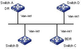
|
Device |
Interface |
IP address |
Router ID |
Interface priority |
|
Switch A |
Vlan-int1 |
196.1.1.1/24 |
1.1.1.1 |
100 |
|
Switch B |
Vlan-int1 |
196.1.1.2/24 |
2.2.2.2 |
0 |
|
Switch C |
Vlan-int1 |
196.1.1.3/24 |
3.3.3.3 |
2 |
|
Switch D |
Vlan-int1 |
196.1.1.4/24 |
4.4.4.4 |
1 |
Figure 4-3 DR election based on OSPF priority
III. Configuration procedure
# Configure Switch A.
<SwitchA> system-view
[SwitchA] interface Vlan-interface 1
[SwitchA-Vlan-interface1] ip address 196.1.1.1 255.255.255.0
[SwitchA-Vlan-interface1] ospf dr-priority 100
[SwitchA] router id 1.1.1.1
[SwitchA] ospf
[SwitchA-ospf-1] area 0
[SwitchA-ospf-1-area-0.0.0.0] network 196.1.1.0 0.0.0.255
# Configure Switch B.
<SwitchB> system-view
[SwitchB] interface Vlan-interface 1
[SwitchB-Vlan-interface1] ip address 196.1.1.2 255.255.255.0
[SwitchB-Vlan-interface1] ospf dr-priority 0
[SwitchB] router id 2.2.2.2
[SwitchB] ospf
[SwitchB-ospf-1] area 0
[SwitchB-ospf-1-area-0.0.0.0] network 196.1.1.0 0.0.0.255
# Configure Switch C.
<SwitchC> system-view
[SwitchC] interface Vlan-interface 1
[SwitchC-Vlan-interface1] ip address 196.1.1.3 255.255.255.0
[SwitchC-Vlan-interface1] ospf dr-priority 2
[SwitchC] router id 3.3.3.3
[SwitchC] ospf
[SwitchC-ospf-1] area 0
[SwitchC-ospf-1-area-0.0.0.0] network 196.1.1.0 0.0.0.255
# Configure Switch D.
<SwitchD> system-view
[SwitchD] interface Vlan-interface 1
[SwitchD-Vlan-interface1] ip address 196.1.1.4 255.255.255.0
[SwitchD] router id 4.4.4.4
[SwitchD] ospf
[SwitchD-ospf-1] area 0
[SwitchD-ospf-1-area-0.0.0.0] network 196.1.1.0 0.0.0.255
On Switch A, execute the display ospf peer command to display its OSPF peers. Note that Switch A has three peers.
The state of each peer is full, which means that adjacency is established between Switch A and each peer. Switch A and Switch C must establish adjacencies with all the switches on the network so that they can serve as the DR and BDR respectively on the network. Switch A is DR, while Switch C is BDR on the network. All the other neighbors are DR others (This means that they are neither DRs nor BDRs).
# Change the priority of Switch B to 200.
<SwitchB> system-view
[SwitchB] interface Vlan-interface 2000
[SwitchB-Vlan-interface2000] ospf dr-priority 200
On Switch A, run the display ospf peer command to display its OSPF peers. Note that the priority of Switch B has been changed to 200, but it is still not the DR.
The DR is changed only when the current DR turn offline. Shut down Switch A, and run the display ospf peer command on Switch D to display its peers. Note that the original BDR (Switch C) becomes the DR and Switch B becomes BDR now.
If all Ethernet Switches on the network are removed from and then added to the network again, Switch B will be elected as the DR (with a priority of 200), and Switch A will be the BDR (with a priority of 100). Shutting down and restarting all of the switches will bring about a new round of DR/BDR selection.
4.9.2 Configuring OSPF Virtual Link
I. Network requirements
As shown in Figure 4-4, Area 2 and Area 0 are not directly interconnected. It is required to use Area 1 as a transition area for interconnecting Area 2 and Area 0. Correctly configure a virtual link between Switch B and Switch C in Area 1.
II. Network diagram
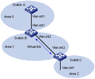
|
Device |
Interface |
IP interface |
Router ID |
|
Switch A |
Vlan-int1 |
196.1.1.1/24 |
1.1.1.1 |
|
Switch B |
Vlan-int1 |
196.1.1.2/24 |
2.2.2.2 |
|
|
Vlan-int2 |
197.1.1.2/24 |
|
|
Switch C |
Vlan-int1 |
152.1.1.1/24 |
3.3.3.3 |
|
|
Vlan-int2 |
197.1.1.1/24 |
|
Figure 4-4 OSPF virtual link configuration
III. Configuration procedure
# Configure Switch A.
<SwitchA> system-view
[SwitchA] interface Vlan-interface 1
[SwitchA-Vlan-interface1] ip address 196.1.1.1 255.255.255.0
[SwitchA-Vlan-interface1] quit
[SwitchA] router id 1.1.1.1
[SwitchA] ospf
[SwitchA-ospf-1] area 0
[SwitchA-ospf-1-area-0.0.0.0] network 196.1.1.0 0.0.0.255
# Configure Switch B.
<SwitchB> system-view
[SwitchB] interface vlan-interface 1
[SwitchB-Vlan-interface1] ip address 196.1.1.2 255.255.255.0
[SwitchB-Vlan-interface1] quit
[SwitchB] interface vlan-interface 2
[SwitchB-Vlan-interface2] ip address 197.1.1.2 255.255.255.0
[SwitchB] router id 2.2.2.2
[SwitchB] ospf
[SwitchB-ospf-1] area 0
[SwitchB-ospf-1-area-0.0.0.0] network 196.1.1.0 0.0.0.255
[SwitchB-ospf-1-area-0.0.0.0] quit
[SwitchB-ospf-1] area 1
[SwitchB-ospf-1-area-0.0.0.1] network 197.1.1.0 0.0.0.255
[SwitchB-ospf-1-area-0.0.0.1] vlink-peer 3.3.3.3
# Configure Switch C.
<SwitchC> system-view
[SwitchC] interface Vlan-interface 1
[SwitchC-Vlan-interface1] ip address 152.1.1.1 255.255.255.0
[SwitchC-Vlan-interface1] quit
[SwitchC] interface Vlan-interface 2
[SwitchC-Vlan-interface2] ip address 197.1.1.1 255.255.255.0
[SwitchC-Vlan-interface2] quit
[SwitchC] router id 3.3.3.3
[SwitchC] ospf
[SwitchC-ospf-1] area 1
[SwitchC-ospf-1-area-0.0.0.1] network 197.1.1.0 0.0.0.255
[SwitchC-ospf-1-area-0.0.0.1] quit
[SwitchC-ospf-1-area-0.0.0.1] vlink-peer 2.2.2.2
[SwitchC-ospf-1-area-0.0.0.2] network 152.1.1.0 0.0.0.255
4.10 Troubleshooting OSPF Configuration
Symptom 1: OSPF has been configured in accordance with the above-mentioned steps, but OSPF does not run normally on the switch.
Solution: Perform the following procedure.
Local fault removal:
Check whether the protocol works normally between two directly connected routers. The normal sign is that the peer state machine between the two routers is in the FULL state.
Note: On a broadcast or NBMA network, if the interfaces between two routers are in DROther state, the peer state machine between the two routers are in 2-way state, instead of FULL state. The peer state machine between DR/BDR and all the other routers is in FULL state.
l Use the display ospf peer command to view peers.
l Use the display ospf interface command to view the OSPF information on an interface.
l Check whether the physical connection is correct and the lower layer protocol operates normally. You can use the ping command to test. If the local router cannot ping the peer router, this indicates that faults exist on the physical link and the lower level protocol.
l If the physical connection and the lower layer protocol are normal, check the OSPF parameters configured on the interface. Verify that these parameter configurations are consistent with those on the peer interface. The area IDs must be the same, and the network segments and the masks must also be consistent (p2p or virtually linked segments can have different segments and masks).
l Ensure that the dead timer value is at least four times of the hello timer value on the same interface.
l If the network type is NBMA, you must use the peer ip-address command to manually specify a peer.
l If the network type is broadcast or NBMA, ensure that there is at least one interface with a priority greater than zero.
l If an area is set to a stub area, ensure that the area is set to a stub area for all the routers connected to this area.
l Ensure that the interface types of two neighboring routers are consistent.
l If two or more areas are configured, ensure that at least one area is configured as the backbone area; that is, the area ID of an area is 0.
l Ensure that the backbone area is connected to all the other areas.
l Ensure that no virtual link passes through a stub area.
Global fault removal:
If OSPF still cannot discover the remote routes after the above procedure, check the following configurations:
l If two or more areas are configured on a router, at least one area should be configured to be connected to the backbone area.
As shown in Figure 4-5, RTA and RTD belong to only one area, whereas RTB (area 0 and area 1) and RTC (area 1 and area 2) belong to two areas. One of the areas of RTB is area 0 (the backbone area). However, neither areas of RTC is area 0. Therefore, a virtual link should be set up between RTC and RTB to ensure that Area 2 and Area 0 are interconnected.
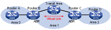
l A virtual link cannot pass through a stub area. The backbone area (area 0) cannot be configured as a stub area. So, if a virtual link has been set up between RTB and RTC, neither area 1 nor area 0 can be configured as a stub area. In Figure 4-5, only area 2 can be configured as a stub area.
l A router in a stub area cannot receive external routes.
l The backbone area must guarantee the connectivity between various nodes.
Chapter 5 IS-IS Configuration
When configuring IS-IS, go to these sections for information you are interested in:
l IS-IS Configuration Task List
l Displaying and Maintaining Integrated IS-IS Configuration
l Integrated IS-IS Configuration Example
5.1 IS-IS Overview
The intermediate system-to-intermediate system (IS-IS) is a dynamic routing protocol standardized by the International Organization for Standardization (ISO) to operate on connectionless network protocol (CLNP).
The IS-IS routing protocol has been adopted in RFC 1195 by the International Engineer Task Force (IETF) to be applied in both TCP/IP and OSI reference models, and this form is called Integrated IS-IS or Dual IS-IS.
The IS-IS routing protocol, based on the link state algorithm, is an interior gateway protocol (IGP) used within an Autonomous System. It is similar to open shortest path first (OSPF) using shortest path first (SPF) algorithm to calculate best paths in the network.
5.1.1 Basic Concept
I. IS-IS terminology
l Intermediate system (IS). An IS, similar to a router in TCP/IP, is the basic unit in IS-IS protocol to generate and propagate routing information. In the following text, an IS equals to a router.
l End system (ES). An ES refers to a host system in TCP/IP. ISO uses ES-IS protocol to specify the communication between an ES and an IS, therefore an ES does not participate in the IS-IS process and can be ignored in the IS-IS protocol.
l Routing domain (RD). A group of ISs exchange routing information with the same routing protocol in a routing domain.
l Area. An area is a division unit in a routing domain. The IS-IS protocol allows a routing domain to be divided into multiple areas.
l Link state database (LSDB). All link states in the network consist of the LSDB. There is at least one LSDB in each IS. The IS uses SPF algorithm and LSDB to generate its own routes.
l Link state protocol data unit or link state packet (LSP). In the IS-IS routing protocol, each IS can generate a LSP which contains all the link state information of the IS. Each IS collects all the LSPs in the local area to generate its own LSDB.
l Network protocol data unit (NPDU). An NPDU is a network layer protocol packet in OSI, which is equivalent to an IP packet in TCP/IP.
l Designated IS (DIS). On a broadcast network, the designated router is also known as the designated IS.
l Network service access point (NSAP). The NSAP is the OSI network layer address. It identifies an abstract network service access point and describes the network address in the OSI reference model.
II. IS-IS network types
IS-IS supports two network types:
l Broadcast networks, such as Ethernet and Token-Ring
l Point-to-point networks, such as PPP and HDLC
For non-broadcast multi-access (NBMA) network, such as ATM, you need to configure point-to-point or broadcast network on its sub-interfaces. IS-IS does not run on point to multipoint (P2MP) links.
5.1.2 IS-IS Domain
I. Two-level hierarchy
The IS-IS uses two-level hierarchy in the routing domain to support large scale routing networks. A large routing domain is divided into multiple Areas. The Level-1 router is in charge of forwarding routes within an area, and the Level-2 router is in charge of forwarding routes between areas.
II. Level-1 and Level-2
1) Level-1 router
The Level-1 router only forms the neighbor relationship with Level-1 and Level-1-2 routers in the same area. The LSDB maintained by the Level-1 router contains the local area routing information. It directs the packets out of the area to the nearest Level-2 router.
2) Level-2 router
The Level-2 router forms the neighbor relationship with the Level-2 and Level-1-2 routers in the same or in different areas. It maintains a Level-2 LSDB which contains routing information for routing between areas. All Level-2 routers must be contiguous to form the backbone in a routing domain. Only Level-2 routers can directly communicate with routers outside the routing domain. Level-2 routers in a routing domain must be contiguous to ensure a contiguous backbone network.
3) Level-1-2 router
A router that functions as a Level-1 and a Level-2 router is called a Level-1-2 router. It can form the Level-1 neighbor relationship with the Level-1 and Level-1-2 routers in the same area, or form Level-2 neighbor relationship with the Level-2 and Level-1-2 routers in different areas. A Level-1 router must be connected to other areas through a Level-1-2 router. The Level-1-2 router maintains two LSDBs, where the Level-1 LSDB is for routing within the area, and the Level-2 LSDB is for routing between areas.
& Note:
l The Level-1 routers in different areas can not form the neighbor relationship.
l Level-2 routers can reside in different areas.
Figure 5-1 shows a network topology running the IS-IS protocol. It is similar to the multiple-area OSPF topology. Area 1 is a set of the Level-2 routers, called backbone network. The other 4 areas are non-backbone networks connected to the backbone through Level-1-2 routers.
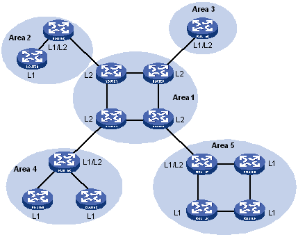
Figure 5-1 An example of the IS-IS topology I
Figure 5-2 shows another network topology running the IS-IS protocol. The Level-1-2 routers connect the Level-1 and Level-2 routers, and also forms the IS-IS backbone together with the Level-2 routers. There is no area defined as the backbone in this topology. The backbone is composed of all contiguous Level-2 routers which can reside in different areas.
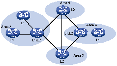
Figure 5-2 An example of the IS-IS topology II
& Note:
The IS-IS backbone does not need to be a particular Area.
In IS-IS, SPF algorithm is used to generate the shortest path tree (SPT) regardless of the Level-1 or Level-2 router.
5.1.3 IS-IS Address Structure
I. Address structure
1) NSAP
The ISO uses the NSAP address format shown in Figure 5-3. The NSAP address consists of the initial domain part (IDP) and the domain specific part (DSP). The IDP equals to the network id field in the IP address, and the DSP equals to the subnet and host id field.
The IDP, defined by OSI, includes the authority and format identifier (AFI) and the initial domain identifier (IDI).
The DSP includes the high order DSP (HODSP), the System ID and SEL, where the HODSP identifies the area, the System ID identifies the host, and the SEL indicates the type of service.
The length of IDP and DSP is variable. The maximum length of the NSAP address is 20 bytes.
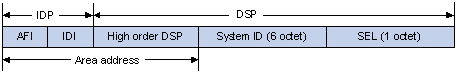
Figure 5-3 NSAP address structure
2) Area address
The area address is composed of the IDP and the HODSP of the DSP, which identify the area and the routing domain. This is equal to the area number in OSPF.
In normal condition, a router only needs one area address, and all nodes must share the same area addresses in the same domain.
3) System ID
A system ID identifies a host or router uniquely. Its length has multiple options. For S7500 series Ethernet switches, the length of the system ID is 48 bits (6 bytes).
The system ID is used together with the Router ID in practice. For example, a router uses the IP address 168.10.1.1 of the Loopback 0 as the Router ID, you can get the system ID used in IS-IS though the following method:
l Extend each field of the IP address to 3 digits with putting 0s from the left;
l Divide the extended IP address into 3 sections with 4 digits in each section, so the System ID is 1680.1000.1001.
There are other methods to define a system ID. Just make sure it can uniquely identify the host or router.
4) SEL
The NSAP Selector (SEL), sometimes present in N-SEL, is used as the protocol identifier in IP. Different transmission protocols use different SELs. All SELs in IP are 00.
Because the area is explicitly defined in the address structure, the Level-1 router can easily recognize the packets sent out of the area. Those packets are forwarded to the Level-2 router.
The Level-1 router makes routing decisions based on the system ID. If the destination is not in the area, the packet is forwarded to the nearest Level-1-2 router.
Level-2 routers perform routing between areas according to the area address (IDP+HO-DSP).
II. NET
The network entity title (NET) is an NSAP with SEL of 0. It indicates the network layer information of the IS itself. SEL=0 means it provides no transport layer information.
In normal condition, a router only needs one NET. But a router can have three NETs at most for smooth area merging and partitioning.
For example, there is a NET named 47.0001.aaaa.bbbb.cccc.00, where:
Area=47.0001, System ID=aaaa.bbbb.cccc, SEL=00.
Here is another example. A NET named 01.1111.2222.4444.00 exists where:
Area=01, System ID=1111.2222.4444, SEL=00.
5.1.4 IS-IS PDU Format
Directly encapsulated in data link layer frames, IS-IS packets fall into three categories: Hello, LSP, and SNP.
I. Hello
The Hello packet is used by routers to establish and maintain the neighbor relationship. It is also called IS-to-IS Hello PDUs (IIH). For broadcast network, the Level-1 router uses the Level-1 LAN IIH; and the Level-2 router uses the Level-2 LAN IIH. The P2P IIH is used on point-to-point network. Point-to-Point IIH is used on a non-broadcast network.
II. LSP packet format
The link state PDUs (LSP) carry link state information. There are two types: Level-1 LSP and Level-2 LSP. The Level-2 LSP is sent by the Level-2 router, and the Level-1 LSP is sent by the Level-1 router. The level-1-2 router can sent both types of the LSPs.
III. SNP format
The sequence number PDUs (SNP) confirms the latest LSPs received by neighbors. It is similar to the Acknowledge packet, but more efficient.
The SNP contains the complete SNP (CSNP) and the partial SNP (PSNP), which are further divided into Level-1 CSNP, Level-2 CSNP, Level-1 PSNP and Level-2 PSNP.
PSNP only contains the sequence numbers of one or multiple latest received LSPs. It can acknowledge multiple LSPs at one time. When LSDBs are not synchronized, a PSNP is used to request new LSPs from neighbors.
CSNP covers the summary of all LSPs in the LSDB to synchronize the LSDB between neighboring routers. On broadcast networks, CSNP is sent by the DIS periodically (10s by default). On point-to-point networks, CSNP is only sent during the first adjacency establishment.
5.2 IS-IS Configuration Task List
Complete the following tasks to configure IS-IS:
|
Task |
Remarks |
|
|
Required |
||
|
Required |
||
|
Required |
||
|
Optional |
||
|
Optional |
||
|
Optional |
||
|
Optional |
||
|
Optional |
||
|
Optional |
||
|
Optional |
||
|
Optional |
||
|
Optional |
||
|
Optional |
||
|
Optional |
||
|
Optional |
||
|
Optional |
||
|
Optional |
||
|
Optional |
||
|
Optional |
||
|
Optional |
||
|
Optional |
||
|
Optional |
||
|
Optional |
||
|
Optional |
||
|
Optional |
||
|
Optional |
||
|
Optional |
||
5.3 IS-IS Basic Configuration
All configuration tasks, except enabling IS-IS, are optional.
This section covers the following topics:
1) IS-IS basic configuration
l Enabling IS-IS
l Configuring a NET
l Enabling IS-IS on the specified interface
l Configuring DIS priority
l Configuring router type
l Configuring line type of an interface
2) IS-IS route configuration
l Configuring route redistribution
l Configuring route filtering
l Configuring route leaking
l Configuring route summarization
l Configuring default route generation
3) IS-IS-related configuration:
l Configuring IS-IS priority
l Configuring IS-IS timers
l Configuring routing cost type
l Configuring link state routing cost
l Configuring LSP parameters
l Configuring SPF parameters
4) Networking configuration
l Configuring authentication
l Configuring overload tag
l Configuring adjacency state output
l Configuring a mesh group for an interface
l Disabling the sending of IS-IS packets
5) Some operation commands
l Clearing IS-IS data structure
l Clearing IS-IS specific neighbor
5.3.1 Enabling IS-IS
IS-IS can be enabled only after you create an IS-IS routing process and enable this routing process on the interfaces that may be associated with other routers.
Follow these steps to enable IS-IS:
|
To do... |
Use the command... |
Remarks |
|
Enter system view |
system-view |
— |
|
Configure ISIS |
isis [ tag ] |
Required By default, no IS-IS routing process is enabled. |
5.3.2 Configuring a NET
A NET defines the current IS-IS area address and router system ID.
Follow these steps to configure a NET:
|
To do... |
Use the command... |
Remarks |
|
Enter system view |
system-view |
— |
|
Enter IS-IS view |
isis [ tag ] |
— |
|
Enable network entity |
network-entity net |
Required |
5.3.3 Enabling IS-IS on the Specified Interface
Follow these steps to enable IS-IS on the specified interface:
|
To do... |
Use the command... |
Remarks |
|
Enter system view |
system-view |
— |
|
Enter interface view |
interface interface-type interface-number |
— |
|
Enable IS-IS |
isis enable [ tag ] |
Required |
5.3.4 Configuring DIS Priority
In a broadcast network, IS-IS needs to select a router as DIS.
When a DIS needs to be selected from the IS-IS neighbors on the broadcast network, the Level-1 DIS and Level-2 DIS should be selected respectively. The higher priority a DIS has, the more likely it is to be chosen. If two or more routers with the highest priorities exist on the broadcast network, the router that has the greatest MAC address will be chosen. For adjacent routers that have the same priority of 0, the router that has the greatest MAC address will still be chosen.
Level-1 DIS and Level-2 DIS are elected respectively. You can set different priorities for DISs at different levels to be elected.
Follow these steps to configure DIS priority:
|
To do... |
Use the command... |
Remarks |
|
Enter system view |
system-view |
— |
|
Enter interface view |
interface interface-type interface-number |
— |
|
Assign a DIS priority |
isis dis-priority value [ level-1 | level-2 ] |
Optional The default DIS priority is 64. |
5.3.5 Configuring Router Type
Follow these steps to configure router type:
|
To do... |
Use the command... |
Remarks |
|
Enter system view |
system-view |
— |
|
Enter IS-IS view |
isis [ tag ] |
— |
|
Configure router type |
is-level { level-1 | level-1-2 | level-2 } |
Required By default, the router type is level-1-2. |
5.3.6 Configuring the Line Type of an Interface
Follow these steps to configure the interface line type:
|
To do... |
Use the command... |
Remarks |
|
Enter system view |
system-view |
— |
|
Enter interface view |
interface interface-type interface-number |
— |
|
Configure the line type of an interface |
isis circuit-level [ level-1 | level-1-2 | level-2 ] |
Required The default line type is level-1-2. |
& Note:
Changing interface line type makes sense only when the interface is on a Level-1-2 router. Otherwise, the router type determines the adjacency hierarchy that can be established.
5.3.7 Configuring Route Redistribution
IS-IS processes the routes discovered by other routing protocols as routes outside a routing domain. You can specify the default cost for IS-IS to redistribute routes from another routing protocol.
You can configure IS-IS to redistribute routes to Level-1, Level-2, and Level-1-2.
Follow these steps to configure route redistribution:
|
To do... |
Use the command... |
Remarks |
|
Enter system view |
system-view |
— |
|
Enter IS-IS view |
isis [ tag ] |
— |
|
Redistribute routes from another protocol |
import-route protocol [ allow-ibgp ] [ cost value | type { external | internal } | [ level-1 | level-1-2 | level-2 ] | route-policy route-policy-name ]* |
Required By default, IS-IS imports no route from another protocol. |
& Note:
l For more about routing information, refer to the section "Configuring an IP Routing Policy".
l Use the keyword allow-ibgp with care when redistributing routes from BGP, because it redistributes IBGP routes without keeping the AS_PATH attribute, which may lead to routing loops between ASs.
5.3.8 Configuring Route Filtering
IS-IS can filter received routes and advertised routes based on ACL numbers.
I. Configuring received route filtering
Follow these steps to configure received route filtering:
|
To do... |
Use the command... |
Remarks |
|
Enter system view |
system-view |
— |
|
Enter IS-IS view |
isis [ tag ] |
— |
|
Set the policy for filtering received routes |
filter-policy acl-number import |
Required By default, IS-IS does not filter received routes. |
II. Configuring IS-IS to filter the routes advertised by other routing protocols
Follow these steps to configure IS-IS to filter the routes advertised by other routing protocols:
|
To do... |
Use the command... |
Remarks |
|
Enter system view |
system-view |
— |
|
Enter IS-IS view |
isis [ tag ] |
— |
|
Set the policy for filtering the routes advertised by other protocols |
filter-policy acl-number export [ protocol ] |
Required By default, IS-IS does not receive the routes advertised by other routing protocols. |
& Note:
l The filter-policy import command filters only the IS-IS routes received from neighbors. The routes that cannot pass the filtering will not be added to the routing table.
l The filter-policy export command only applies to the routes imported with the import-route command. The filter-policy export command will not work if you do not configure the import-route command to import non-IS-IS routes.
l If you do not specify which type of routes are to be filtered with the filter-policy export command, all the routes imported with the import-route command will be filtered.
5.3.9 Configuring Route Leaking
Through route leaking, a Level-2 router can send the Level-1 area routing information and Level-2 area routing information that it knows to a Level-1 router.
Follow these steps to configure route leaking:
|
To do... |
Use the command... |
Remarks |
|
Enter system view |
system-view |
— |
|
Enter IS-IS view |
isis [ tag ] |
— |
|
Enable route leaking |
import-route isis level-2 into level-1 [ acl acl-number ] |
Required By default, a Level-2 router sends no routing information to a Level-1 area. |
5.3.10 Configuring Route Summarization
You can configure the routes having the same IP prefix as one summarized route.
Follow these steps to configure route summarization:
|
To do... |
Use the command... |
Remarks |
|
Enter system view |
system-view |
— |
|
Enter IS-IS view |
isis [ tag ] |
— |
|
Configure route summarization |
summary ip-address ip-mask [ level-1 | level-1-2 | level-2 ] |
Required By default, the system performs no route summarization. |
5.3.11 Configuring Default Route Generation
In an IS-IS routing domain, a Level-1 router maintains the LSDB for the local area only and generates the routes within the local area only. A Level-2 router maintains the LSDB for the backbone within the IS-IS routing domain and generates the routes for the backbone only. To transfer packets to another area, a Level-1 router in an area needs to first transfer the packets to the nearest Level-1-2 router within the local area. This requires the default route at Level-1.
Follow these steps to configure default route generation:
|
To do... |
Use the command... |
Remarks |
|
Enter system view |
system-view |
— |
|
Enter IS-IS view |
isis [ tag ] |
— |
|
Configure default route generation |
default-route-advertise [ route-policy route-policy-name ] |
Required The default route is advertised to only the routers at the same level. |
5.3.12 Configuring Protocol Priority
For a router running multiple routing protocols, routing information needs to be shared and selected by the routing protocols. The system assigns a priority for each routing protocol. When multiple routing protocols discover a route to the same destination, the protocol with the highest priority will dominate.
Follow these steps to configure protocol priority:
|
To do... |
Use the command... |
Remarks |
|
Enter system view |
system-view |
— |
|
Enter IS-IS view |
isis [ tag ] |
— |
|
Configure protocol priority |
preference [ value | clns | ip ] |
Required The default priority of IS-IS routes is 15. |
5.3.13 Configuring a Cost Style
In IS-IS routing protocol, routing cost of a link can be expressed in one of the following two modes:
l Narrow: In this mode, routing cost ranges from 1 to 63.
l Wide: In this mode, routing cost ranges from 1 to 224-1, namely, 1 to 16,777,215.
You can specify to support either mode or both.
Follow these steps to configure IS-IS route cost style:
|
To do... |
Use the command... |
Remarks |
|
Enter system view |
system-view |
— |
|
Enter IS-IS view |
isis [ tag ] |
— |
|
Configure a cost style |
cost-style { narrow | wide | wide-compatible | { compatible | narrow-compatible } [ relax-spf-limit ] } |
Required By default, IS-IS receives/sends only the packets with routing cost expressed in the Narrow mode. |
5.3.14 Configuring Interface Cost
Follow these steps to configure interface cost:
|
To do... |
Use the command... |
Remarks |
|
Enter system view |
system-view |
— |
|
Enter interface view |
interface interface-type interface-number |
— |
|
Configure interface cost |
isis cost value [ level-1 | level-2 ] |
Required The default IS-IS interface cost is 10. |
5.3.15 Configuring IS-IS Timer
I. Configuring the Hello interval
In IS-IS, Hello packets are sent periodically through interfaces and routers maintain neighbor relationship by sending and receiving Hello packets. You can configure the Hello interval.
Follow these steps to configure the Hello interval:
|
To do... |
Use the command... |
Remarks |
|
Enter system view |
system-view |
— |
|
Enter interface view |
interface interface-type interface-number |
— |
|
Define the Hello packet sending interval, in seconds |
isis timer hello seconds [ level-1 | level-2 ] |
Required The default Hello packets sending interval is 10 seconds. |
II. Configuring the CSNP packets sending interval
CSNP packets are the packets sent with the synchronous LSDB by the DIS on a broadcast network. CSNP packets are broadcast periodically on a broadcast network. You can configure the interval of sending CSNP packets.
Follow these steps to configure the CSNP packets sending interval:
|
To do... |
Use the command... |
Remarks |
|
Enter system view |
system-view |
— |
|
Enter interface view |
interface interface-type interface-number |
— |
|
Configure the CSNP packets sending interval, in seconds |
isis timer csnp seconds [ level-1 | level-2 ] |
Required The default CSNP packets sending interval is 10 seconds. |
III. Configuring the LSP sending interval
LSPs are used to advertise link state records within an area.
Follow these steps to configure the LSP sending interval:
|
To do... |
Use the command... |
Remarks |
|
Enter system view |
system-view |
— |
|
Enter interface view |
interface interface-type interface-number |
— |
|
Configure the LSP sending interval, in milliseconds |
isis timer lsp time |
Required The default LSP sending interval is 33 milliseconds. |
IV. Configuring the LSP retransmitting interval on an interface
On a point-to-point link, if there is no response for the sent LSP, the LSP is considered lost or discarded and the sending router retransmits the LSP.
Follow these steps to configure LSP retransmitting interval:
|
To do... |
Use the command... |
Remarks |
|
Enter system view |
system-view |
— |
|
Enter interface view |
interface interface-type interface-number |
— |
|
Configure the LSP retransmitting interval on a point-to-point link |
isis timer retransmit seconds |
Required By default, LSPs are retransmitted on a point-to-point link every five seconds. |
V. Configuring the number of Hello packets expected from the remote router before it is considered dead
In IS-IS, Hello packets are sent and received to maintain router neighbor relationships. If a router does not receive any Hello packet from a neighboring router in a certain period of time (Holddown time in IS-IS), the neighbor is considered dead.
In IS-IS, you can adjust the Holddown time by configuring the number of Hello packets expected from a neighbor router before it is considered dead.
Follow these steps to configure the number of Hello packets expected from the remote router before it is considered dead:
|
To do... |
Use the command... |
Remarks |
|
Enter system view |
system-view |
— |
|
Enter interface view |
interface interface-type interface-number |
— |
|
Configure the number of Hello packets expected from the remote router before it is considered dead |
isis timer holding-multiplier value [ level-1 | level-2 ] |
Required By default, three Hello packets are expected from the remote router before it is considered dead. |
& Note:
If you do not provide the level-1 keyword or the level-2 keyword, this command applies to Level-1 and Level-2.
5.3.16 Configuring Authentication
I. Configuring authentication on an interface
The authentication configured on the interface applies to the Hello packet in order to authenticate neighbors. All interfaces must share the same authentication password in the same level within a network.
Follow these steps to configure authentication:
|
To do... |
Use the command... |
Remarks |
|
Enter system view |
system-view |
— |
|
Enter interface view |
interface interface-type interface-number |
— |
|
Configure the IS-IS authentication mode and password |
isis authentication-mode { simple | md5 } password [ { level-1 | level-2 } [ ip | osi ] ] |
Required By default, no authentication is configured. |
II. Configuring authentication for an IS-IS area or routing domain
You can configure an authentication password for an IS-IS area or routing domain.
If area authentication is required, the area authentication password is encapsulated in the LSP, CSNP, and PSNP packets at Level-1 as predefined. If area authentication is also enabled on other routers in the same area, area authentication works normally only if the authentication mode and password of these routers are the same as those of the neighboring routers.
Likewise, if domain authentication is required, the domain authentication password is also encapsulated in the LSP, CSNP, and PSNP packets at Level-2 as predefined. If domain authentication is also required on other routers at the backbone layer (Level-2), the authentication works normally only if the authentication mode and password of these routers are the same as those of the neighboring routers.
Follow these steps to configure authentication:
|
To do... |
Use the command... |
Remarks |
|
Enter system view |
system-view |
— |
|
Enter IS-IS view |
isis [ tag ] |
— |
|
Define the area authentication mode |
area-authentication-mode { simple | md5 } password [ ip | osi ] |
Optional |
|
Define the domain authentication mode |
domain-authentication-mode { simple | md5 } password [ ip | osi ] |
Optional By default, no password is defined and no authentication is enabled. |
III. Configuring IS-IS to use an MD5 algorithm compatible with the switches of other manufacturers
To enable IS-IS MD5 authentication between the switch and the switches of other manufacturers, you must use the following commands to configure IS-IS to use an MD5 algorithm compatible with the switches of other manufacturers.
Follow these steps to configure IS-IS to use an MD5 algorithm compatible with the switches of other manufacturers:
|
To do... |
Use the command... |
Remarks |
|
Enter system view |
system-view |
— |
|
Enter IS-IS view |
isis [ tag ] |
— |
|
Configure IS-IS to use an MD5 algorithm compatible with the switches of other manufacturers |
md5-compatible |
Optional |
|
Configure IS-IS to use the default MD5 algorithm |
undo md5-compatible |
Optional By default, the Huawei-compatible MD5 algorithm is used. |
5.3.17 Adding an Interface to a Mesh Group
On an NBMA network, a router floods a new LSP received from an interface to other interfaces of the router. This can cause repeated LSP flooding on a high-connectivity network with multiple point-to-point links, which is a waste of the bandwidth.
To avoid this problem, you can add interfaces into a mesh group. The interfaces in the group will flood the new LSPs to only the interfaces outside the mesh group.
Follow these steps to add an interface to a mesh group:
|
To do... |
Use the command... |
Remarks |
|
Enter system view |
system-view |
— |
|
Enter interface view |
interface interface-type interface-number |
— |
|
Add an interface to a mesh group |
isis mesh-group { mesh-group-number | mesh-blocked } |
Required By default, LSPs are flooded on interfaces normally. |
5.3.18 Configuring Overload Tag
A failure of a router in an IS-IS domain will cause errors in the routing of the whole domain. To avoid this, you can configure the overload tag for the routers.
When the overload tag is set, other routers will not ask the router to forward packets.
Follow these steps to configure overload tag:
|
To do... |
Use the command... |
Remarks |
|
Enter system view |
system-view |
— |
|
Enter IS-IS view |
isis [ tag ] |
— |
|
Configure overload tag |
set-overload |
Required No overload tag is set by default. |
5.3.19 Configuring to Discard LSPs with Incorrect Checksum
Checksum is performed on the LSPs received locally by IS-IS and compared with that carried in the LSPs. By default, the LSP will not be discarded even if its checksum is inconsistent with that calculated.
Follow these steps to configure IS-IS to discard LSPs with incorrect checksum:
|
To do... |
Use the command... |
Remarks |
|
Enter system view |
system-view |
— |
|
Enter IS-IS view |
isis [ tag ] |
— |
|
Configure to discard LSPs with incorrect checksum |
ignore-lsp-checksum-error |
Required By default, LSP checksum error is ignored. |
5.3.20 Configuring to Log Peer Changes
With peer state logging enabled, IS-IS peer state changes are output to the console terminal.
Follow these steps to enable peer change logging:
|
To do... |
Use the command... |
Remarks |
|
Enter system view |
system-view |
— |
|
Enter IS-IS view |
isis [ tag ] |
— |
|
Enable peer change logging |
log-peer-change |
Required By default, peer change logging is disabled. |
5.3.21 Assigning an LSP Refresh Time
All LSPs are sent periodically to synchronize the LSPs in an area.
Follow these steps to assign an LSP refresh time:
|
To do... |
Use the command... |
Remarks |
|
Enter system view |
system-view |
— |
|
Enter IS-IS view |
isis [ tag ] |
— |
|
Assign an LSP refresh time |
timer lsp-refresh seconds |
Required By default, LSPs are refreshed every 900 seconds, namely, 15 minutes. |
5.3.22 Assigning an LSP Maximum Aging Time
An LSP is given a maximum aging value when it is generated by the router. When the LSP is sent to other routers, its maximum aging value goes down gradually. If the router does not get the update for the LSP before the maximum aging value reaches 0, the LSP will be deleted from the LSDB.
Follow these steps to assign an LSP maximum aging time:
|
To do... |
Use the command... |
Remarks |
|
Enter system view |
system-view |
— |
|
Enter IS-IS view |
isis [ tag ] |
— |
|
Assign an LSP maximum aging time |
timer lsp-max-age seconds |
Required By default, the LSP maximum aging time is 1,200 seconds, namely, 20 minutes. |
5.3.23 Configuring SPF Parameters
I. Configuring the SPF interval
In IS-IS, a router needs to recalculate the shortest path when the LSDB changes. Recalculating the shortest path upon change consumes enormous resources as well as affects the operation efficiency of the router. With an SPF calculation interval configured, when the LSDB changes, the SPF algorithm is not executed until the SPF timer expires.
Follow these steps to configure the SPF interval:
|
To do... |
Use the command... |
Remarks |
|
Enter system view |
system-view |
— |
|
Enter IS-IS view |
isis [ tag ] |
— |
|
Configure the SPF interval |
timer spf seconds [ level-1 | level-2 ] |
Required The default SPF interval is 10 seconds. |
& Note:
If you do not provide the level-1 or level-2 keyword, this command applies to Level-1 and Level-2 by default.
II. Configuring SPF calculation durations
SPF calculation in IS-IS may occupy system resources for a long time if the routing table contains a great number of entries (over 30,000). To avoid this, you can configure SPF calculation durations.
Follow these steps to configure SPF calculation durations:
|
To do... |
Use the command... |
Remarks |
|
Enter system view |
system-view |
— |
|
Enter IS-IS view |
isis [ tag ] |
— |
|
Configure SPF calculation duration |
spf-slice-size seconds |
Required By default, SPF calculation is not sliced. |
III. Configuring SPF to release CPU resources automatically
In IS-IS, SPF calculation may occupy system resources for a long time and slow down console response. To avoid this, you can configure SPF to automatically release CPU resources each time a specified number of routes are processed and continue to calculate the remaining routes after one second.
Follow these steps to configure SPF to release CPU resources automatically:
|
To do... |
Use the command... |
Remarks |
|
Enter system view |
system-view |
— |
|
Enter IS-IS view |
isis [ tag ] |
— |
|
Configure the interval at which SPF releases CPU resources |
spf-delay-interval number |
Required By default, in IS-IS, SPF releases CPU resources each time it has finished processing 5,000 routes. |
5.3.24 Enabling/Disabling Packet Transmission Through an Interface
To prevent IS-IS routing information from being accessed by a router on another network, use the silent-interface command to configure the VLAN interface containing the network segment to receive, but not to send, IS-IS packets.
Follow these steps to enable/disable packet transmission through an interface:
|
To do... |
Use the command... |
Remarks |
|
Enter system view |
system-view |
— |
|
Enter IS-IS view |
isis [ tag ] |
— |
|
Disable an interface from sending IS-IS packets |
silent-interface interface-type interface-number |
Required By default, an interface is enabled to receive and send IS-IS packets. |
5.3.25 Resetting all IS-IS Configuration Data
Perform the following configuration in user view to refresh LSPs immediately.
Follow these steps to reset all IS-IS configuration data:
|
To do... |
Use the command... |
Remarks |
|
Enter system view |
system-view |
— |
|
Reset all IS-IS configuration data |
reset isis all |
Required By default, IS-IS configuration data is not cleared. |
5.3.26 Resetting Configuration Data of an IS-IS Peer
Follow these steps to reset configuration data of the IS-IS peer:
|
To do... |
Use the command... |
Remarks |
|
Enter system view |
system-view |
— |
|
Reset configuration data of an IS-IS peer |
reset isis peer system-id |
Required By default, configuration data of an IS-IS peer is not reset. |
5.4 Displaying and Maintaining Integrated IS-IS Configuration
|
To do... |
Use the command... |
Remarks |
|
Display brief information of IS-IS |
display isis brief |
Available in any view |
|
Display IS-IS link state database |
display isis lsdb [ [ l1 | l2 | level-1 | level-2 ] | [ [ lsp-id | local ] | verbose ]* ]* |
|
|
Display IS-IS SPF logs |
display isis spf-log { ip | clns } |
|
|
Display IS-IS routes |
display isis route |
|
|
Display IS-IS peer information |
display isis peer [ verbose ] |
|
|
Display mesh group information |
display isis mesh-group |
|
|
Display IS-IS interface information |
display isis interface [ verbose ] |
5.5 Integrated IS-IS Configuration Example
I. Network requirements
As shown in Figure 5-4, four S7500 series Ethernet switches (Switch A, Switch B, Switch C, and Switch D) are interconnected through IS-IS routing protocol. In the network design, Switch A, Switch B, Switch C, and Switch D belong to the same area.
II. Network diagram
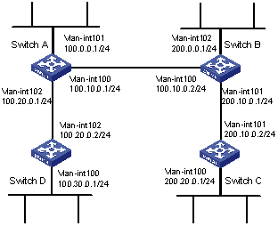
Figure 5-4 Network diagram for IS-IS basic configuration
III. Configuration procedure
# Configure Switch A.
<SwitchA> system-view
[SwitchA] isis
[SwitchA-isis] network-entity 86.0001.0000.0000.0005.00
[SwitchA] interface vlan-interface 100
[SwitchA-Vlan-interface100] ip address 100.10.0.1 255.255.255.0
[SwitchA-Vlan-interface100] isis enable
[SwitchA] interface vlan-interface 101
[SwitchA-Vlan-interface101] ip address 100.0.0.1 255.255.255.0
[SwitchA-Vlan-interface101] isis enable
[SwitchA] interface vlan-interface 102
[SwitchA-Vlan-interface102] ip address 100.20.0.1 255.255.255.0
[SwitchA-Vlan-interface102] isis enable
# Configure Switch B.
[SwitchB] isis
[SwitchB-isis] network-entity 86.0001.0000.0000.0006.00
[SwitchB] interface vlan-interface 101
[SwitchB-Vlan-interface101] ip address 200.10.0.1 255.255.255.0
[SwitchB-Vlan-interface101] isis enable
[SwitchB] interface vlan-interface 102
[SwitchB-Vlan-interface102] ip address 200.0.0.1 255.255.255.0
[SwitchB-Vlan-interface102] isis enable
[SwitchB] interface vlan-interface 100
[SwitchB-Vlan-interface100] ip address 100.10.0.2 255.255.255.0
[SwitchB-Vlan-interface100] isis enable
# Configure Switch C.
[SwitchC] isis
[SwitchC-isis] network-entity 86.0001.0000.0000.0007.00
[SwitchC] interface vlan-interface 101
[SwitchC-Vlan-interface101] ip address 200.10.0.2 255.255.255.0
[SwitchC-Vlan-interface101] isis enable
[SwitchC] interface vlan-interface 100
[SwitchC-Vlan-interface100] ip address 200.20.0.1 255.255.255.0
[SwitchC-Vlan-interface100] isis enable
# Configure Switch D.
[SwitchD] isis
[SwitchD-isis] network-entity 86.0001.0000.0000.0008.00
[SwitchD] interface vlan-interface 102
[SwitchD-Vlan-interface102] ip address 100.20.0.2 255.255.255.0
[SwitchD-Vlan-interface102] isis enable
[SwitchD] interface vlan-interface 100
[SwitchD-Vlan-interface100] ip address 100.30.0.1 255.255.255.0
[SwitchD-Vlan-interface100] isis enable
Chapter 6 BGP Configuration
When configuring BGP, go to these sections for information you are interested in:
l Displaying and Maintaining BGP Configuration
l Troubleshooting BGP Configuration
6.1 BGP Overview
6.1.1 Introduction to BGP
Border gateway protocol (BGP) is a dynamic routing protocol designed to be used between autonomous systems (ASs). An AS is a group of routers that adopt the same routing policy and belong to the same technical management department.
Four versions of BGP exist: BGP-1 (described in RFC 1105), BGP-2 (described in RFC 1163), BGP-3 (described in RFC 1267), and BGP-4 (described in RFC 1771). As the actual Internet exterior routing protocol standard, BGP-4 is widely employed between Internet service providers (ISPs).
& Note:
Unless otherwise noted, BGP in the following sections refers to BGP-4.
BGP has the following features:
l Unlike interior gateway protocols (IGPs) such as OSPF (open shortest path first) and RIP (routing information protocol), BGP is an exterior gateway protocol (EGP). It does not focus on discovering or calculating routes but controlling the route propagation and choosing the optimal route.
l BGP uses TCP (transport control protocol) as the transport layer protocol (with the port number being 179) to ensure reliability.
l BGP supports classless inter-domain routing (CIDR).
l With BGP employed, only the changed routes are propagated. This saves network bandwidth remarkably and makes it feasible to propagate large amount of route information across the Internet.
l The AS path information used in BGP eliminates route loops thoroughly.
l In BGP, multiple routing policies are available for filtering and choosing routes in a flexible way.
l BGP is extendible to allow for new types of networks.
In BGP, the routers that send BGP messages are known as BGP speakers. A BGP speaker receives and generates new routing information, and advertises the information to other BGP speakers. When a BGP speaker receives a route from other AS, if the route is better than the existing routes or the route is new to the BGP speaker, the BGP speaker advertises the route to all other BGP speakers in the AS it belongs to.
A BGP speaker is known as the peer of another BGP speaker if it exchanges messages with the latter. A group of correlated peers can form a peer group.
BGP can operate on a router in one of the following forms.
l IBGP (Internal BGP)
l EBGP (External BGP)
When BGP runs inside an AS, it is called interior BGP (IBGP); when BGP runs among different ASs, it is called exterior BGP (EBGP).
6.1.2 BGP Message Type
I. Format of a BGP packet header
BGP is message-driven. There are five types of BGP packets: Open, Update, Notification, Keepalive, and Route-refresh. They share the same packet header, the format of which is shown by Figure 6-1.
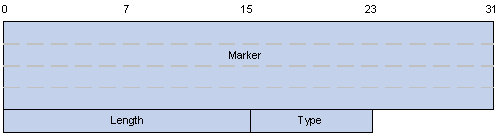
Figure 6-1 Packet header format of a BGP message
The fields in a BGP packet header are described as follows.
l Marker: 16 bytes in length. This filed is used for BGP authentication. When no authentication is performed, all the bits of this field are 1.
l Length: 2 bytes in length. This filed indicates the size (in bytes) of a BGP packet, with the packet header counted in.
l Type: 1 byte in length. This field indicates the type of a BGP packet. Its value ranges from 1 to 5, which represent Open, Update, Notification, Keepalive, and Route-refresh packets. Among these types of BGP packets, the first four are defined in RFC 1771, and the rest one is defined in RFC 2918.
II. Open
Open massage is used to establish connections between BGP speakers. It is sent when a TCP connection is just established. Figure 6-2 shows the format of an Open message.

Figure 6-2 BGP Open message format
The fields are described as follows.
l Version: BGP version. As for BGP-4, its value is 4.
l My Autonomous System: Local AS number. By comparing this filed of both sides, a router can determine whether the connection between itself and the BGP peer is of EBGP or IBGP.
l Hold time: Hold time is to be determined when two BGP speakers negotiate for the connection between them. The Hold times of two BGP peers are the same. A BGP speaker considers the connection between itself and its BGP peer to be terminated if it receives no Keepalive or Update message from its BGP peer during the hold time.
l BGP Identifier: The IP address of a BGP router.
l Opt Parm Len: The length of the optional parameters. A value of 0 indicates no optional parameter is used.
l Optional Parameters: Optional parameters used for BGP authentication or multi-protocol extensions.
III. Update
Update message is used to exchange routing information among BGP peers. It can propagate a reachable route or withdraw multiple pieces of unreachable routes. Figure 6-3 shows the format of an Update message.
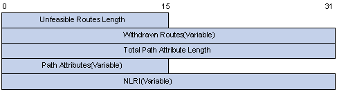
Figure 6-3 BGP Update message format
An Update message can advertise a group of reachable routes with the same path attribute. These routes are set in the NLRI field. The Path Attributes field carries the attributes of these routes, according to which BGP chooses routes. An Update message can also carry multiple unreachable routes. The withdrawn routes are set in the Withdrawn Routes field.
The fields of an Update message are described as follows.
l Unfeasible Routes Length: Length (in bytes) of the unreachable routes field. A value of 0 indicates that there is no Withdrawn Routes filed in the message.
l Withdrawn Routes: Unreachable route list.
l Total Path Attribute Length: Length (in bytes) of the Path Attributes field. A value of 0 indicates that there is no Path Attributes filed in the message.
l Path Attributes: Attributes list of all the paths related to NLRI. Each path attribute is a TLV (Type-Length-Value) triplet. In BGP, loop avoidance, routing, and protocol extensions are implemented through these attribute values.
l NLRI (Network Layer Reachability Information): Contains the information such reachable route suffix and the corresponding suffix length.
IV. Notification
When BGP detects an error state, it sends a Notification message to peers and then tears down the BGP connection. Figure 6-4 shows the format of a Notification message.
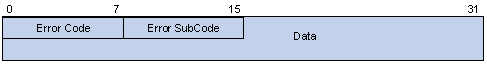
Figure 6-4 BGP Notification message format
The fields of a Notification message are described as follows.
l Error Code: Error code used to identify the error type.
l Error Subcode: Error subcode used to identify the detailed information about the error type.
l Data: Used to further determine the cause of errors. Its content is the error data which depends on the specific error code and error subcode. Its length is unfixed.
V. Keepalive
In BGP, Keepalive message keeps BGP connection alive and is exchanged periodically. A BGP Keepalive message only contains the packet header. No additional field is carried.
VI. Route-refresh
Route-refresh message is used to notify peers that the route refresh function is available.
6.1.3 BGP Routing Mechanism
When BGP initially starts on a router, it sends the whole BGP routing table to its peers to exchange routing information. Afterwards, BGP sends only Update messages instead of the whole table. During this process, BGP also sends/receives Keepalive messages to determine whether the connections to its peers are normal.
A router running BGP is also called a BGP speaker because it can send BGP messages. A BGP speaker can receive routing information as well as generate and advertise routing information to other BGP speakers. When a BGP speaker receives a route from another AS and finds this is a new route (a route it does not know) or a route superior to any of its known routes, the BGP speaker advertises the route to all other BGP speakers in the AS.
Two BGP speakers capable of exchanging BGP messages with each other are peers of each other. Multiple BGP peers can form one peer group.
I. BGP route advertisement policies
In the implementation on H3C S7500 Series Ethernet Switches (hereinafter referred to as the S7500 series), BGP adopts the following policies to advertise routes:
l When there are multiple optional routes, a BGP speaker chooses only the optimal one;
l A BGP speaker advertises only the local routes to its peers;
l A BGP speaker advertises the routes obtained from EBGP to all its BGP peers (including both EBGP and IBGP peers);
l A BGP speaker does not advertise the routes obtained from IBGP to its IBGP peers;
l A BGP speaker advertises the routes obtained from IBGP to its EBGP peers (in the S7500 series, BGP and IGP does not synchronize with each other);
l Once a BGP speaker sets up a connection to a new peer, it advertises all its BGP routes to the new peer.
II. BGP route selection policies
In the implementation on the S7500 series, BGP adopts the following policies for route selection:
l Discard next-hop-unreachable routes;
l Prefer the routes with the highest local-preference;
l Prefer the routes originated from the local router;
l Prefer the routes traversing the least ASs (that is, the routes with the shortest AS-Path);
l Prefer the routes with the lowest Origin type;
l Prefer the routes with the lowest MED value;
l Prefer the routes learned from EBGP;
l Prefer the routes advertised from the router with the lowest BGP ID.
6.1.4 BGP Peer and Peer Group
I. Definition
As described in section 6.1.3 "BGP Routing Mechanism", two BGP speakers capable of exchanging BGP messages with each other are peers of each other. A BGP peer group is a set of BGP peers.
II. Relationship between peer and peer group
In the S7500 series, a BGP peer cannot exist independently; it must belong to a peer group. Therefore, when you configure a BGP peer, make sure you first create a BGP peer group, and then add a peer to the group.
BGP peer groups bring convenience for configuration. Once a peer is added to a peer group, the peer will inherit the same configuration of the peer group. This can simplify configuration in many cases. In addition, adding peers to a peer group can improve route advertisement efficiency.
When the configuration of a peer group changes, the configuration of group members also changes accordingly. For some attributes, you can configure them on a particular member by specifying an IP address; the attribute settings you made in this way on a member take precedence over the attribute settings on the peer group. Note that, the members and the group must have consistent route update policies, but they can have different entrance policies.
6.2 BGP Configuration Task List
Complete the following tasks to configure BGP:
|
Task |
Remarks |
|
|
Required |
||
|
Configuring the Way to Advertise/Receive Routing Information |
Optional |
|
|
Optional |
||
|
Optional |
||
|
Optional |
||
|
Optional |
||
|
Optional |
||
|
Optional |
||
|
Required |
||
|
Optional |
||
|
Optional |
||
|
Required |
||
|
Required |
||
|
Optional |
||
|
Optional |
||
6.3 Basic BGP Configuration
6.3.1 Configuration Prerequisites
Before performing basic BGP configuration, you need to ensure:
l Network layer connectivity between adjacent nodes.
Before performing basic BGP configuration, make sure the following are available.
l Local AS number and router ID
l IPv4 address and AS number of the peers
l Source interface of update packets.
6.3.2 Configuring Basic BGP Functions
Follow these steps to configure basic BGP functions:
|
To do... |
Use the command... |
Remarks |
|
Enter system view |
system-view |
— |
|
Specify the router ID |
router id router-id |
Optional |
|
Enable BGP and enter BGP view |
bgp as-number |
Required By default, BGP is disabled. |
|
Create a peer group |
group group-name [ internal | external ] |
Required |
|
Add a peer to the peer group |
peer peer-address group group-name [ as-number as-number ] |
Required If it is an IBGP peer, you need not specify an AS number. |
|
Set an AS number for the peer group |
peer group-name as-number as-number |
Required By default, a peer group has no AS number. |
|
Assign a description string for a BGP peer/a BGP peer group |
peer { group-name | ip-address } description description-text |
Optional By default, a peer/a peer group is not assigned a description string. |
|
Activate a specified BGP peer |
peer { group-name | ip-address } enable |
Required |
|
Specify the source interface for route update packets |
peer { group-name | ip-address } connect-interface interface-type interface-number |
Optional By default, the source interface of the optimal route update packets is used. |
|
Allow routers that belong to non-directly connected networks to establish EBGP connections. |
peer group-name ebgp-max-hop [hop-count ] |
Optional By default, routers that belong to two non-directly connected networks cannot establish EBGP connections. You can configure the maximum hops of EBGP connection by specifying the hop-count argument. |
![]() Caution:
Caution:
l A router must be assigned a router ID in order to run BGP protocol. A router ID is a 32-bit unsigned integer. It uniquely identifies a router in an AS.
l A router ID can be configured manually. If no router ID is configured, the system will automatically select an IP address from the IP addresses of the interfaces as the router ID. A router ID is selected in the following way: if loopback interface addresses are configured, the system chooses the latest configured IP address as the router ID; if no loopback interface is configured, the first configured IP address among the IP addresses of other interfaces will be the router ID. For network reliability consideration, you are recommended to configure the IP address of a loopback interface as the router ID.
l Router IDs can be re-selected. A re-selected router ID takes effect only after the BGP process is restarted.
l In order for route update packets to be sent even if problems occur on interfaces, you can configure the source interfaces of route update packets as a loopback interface.
l Normally, EBGP peers are connected through directly connected physical links. If no such link exists, you need to use the peer ebgp-max-hop command to allow the peers to establish multiple-hop TCP connections between them.
6.4 Configuring the Way to Advertise/Receive Routing Information
6.4.1 Configuration Prerequisites
Make sure the following operation is performed before configuring the way to advertise/receive BGP routing information.
l Enabling the basic BGP functions
Make sure the following information is available when you configure the way to advertise/receive BGP routing information.
l The aggregation mode and the aggregated route
l Access list number
l Filtering direction (advertising/receiving) and the route policies to be adopted.
l Route dampening settings, such as half-life and the thresholds.
6.4.2 Importing Routes
With BGP employed, an AS can send its interior routing information to its neighbor ASs. However, the interior routing information is not generated by BGP; it is obtained by importing IGP routing information to BGP routing table. Once IGP routing information is imported to BGP routing table, it is advertised to BGP peers. You can filter IGP routing information by routing protocols before the IGP routing information is imported to BGP routing table.
Follow these steps to import routes:
|
To do... |
Use the command... |
Remarks |
|
Enter system view |
system-view |
— |
|
Enter BGP view |
bgp as-number |
— |
|
Import and advertise routing information generated by other protocols. |
import-route protocol [ process-id ] [ med med-value | route-policy route-policy-name ]* |
Required By default, BGP neither import nor advertise the routing information generated by other protocols. |
|
Advertise network segment routes to BGP routing table |
network network-address [ mask ] route-policy route-policy-name ] |
Optional By default, BGP does not advertise any network segment routes. |
![]() Caution:
Caution:
l If a route is imported to the BGP routing table through the import-route command, its Origin attribute is Incomplete.
l The network segment route to be advertised must be in the local IP routing table. You can use routing policy to control route advertising with more flexibility.
l The Origin attribute of the network segment routes advertised to BGP routing table through the network command is IGP.
6.4.3 Configuring BGP Route Aggregation
In a medium-/large-sized BGP network, you can reduce the number of the routes to be advertised to BGP peers through route aggregation to save the space of BGP peer routing tables. BGP supports two route aggregation modes: automatic aggregation mode and manual aggregation mode.
l Automatic aggregation mode, where IGP sub-network routes imported by BGP are aggregated. In this mode, only the aggregated routes are advertised. The imported IGP sub-network routes are not advertised. Note that the default routes and the routes imported by using the network command cannot be automatically aggregated.
l Manual aggregation mode, where local BGP routes are aggregated. The priority of manual aggregation is higher than that of automatic aggregation.
Follow these steps to configure BGP route aggregation:
|
To do... |
Use the command... |
Remarks |
|
|
Enter system view |
system-view |
— |
|
|
Enter BGP view |
bgp as-number |
— |
|
|
Configure BGP route aggregation |
Enable automatic route aggregation |
summary |
Required By default, routes are not aggregated. |
|
Enable manual route aggregation |
aggregate ip-address mask [ as-set | attribute-policy route-policy-name | detail-suppressed | origin-policy route-policy-name | suppress-policy route-policy-name ]* |
||
6.4.4 Enabling Default Route Advertising
Follow these steps to enable default rout advertising:
|
To do... |
Use the command... |
Remarks |
|
Enter system view |
system-view |
— |
|
Enter BGP view |
bgp as-number |
— |
|
Enable default route advertising |
peer group-name default-route-advertise |
Required By default, a BGP router does not send default routes to a specified peer group. |
& Note:
With the peer default-route-advertise command executed, no matter whether the default route is in the local routing table or not, a BGP router sends a default route, whose next hop address is the local address, to the specified peer group.
6.4.5 Configuring the BGP Route Advertising Policy
Follow these steps to configure the BGP route advertising policy:
|
To do... |
Use the command... |
Remarks |
|
|
Enter system view |
system-view |
— |
|
|
Enter BGP view |
bgp as-number |
— |
|
|
Filter the advertised routes |
filter-policy { acl-number | ip-prefix ip-prefix-name } export [ protocol [ process-id ] ] |
Required By default, advertised routes are not filtered. |
|
|
Specify a route advertising policy for the routes advertised to a peer group |
peer group-name route-policy route-policy-name export |
Required By default, no route advertising policy is specified for the routes advertised to a peer group. |
|
|
Filter the routing information to be advertised to a peer group |
Specify an ACL-based BGP route filtering policy for a peer group |
peer group-name filter-policy acl-number export |
Required By default, a peer group has no ACL-based BGP route filtering policy, AS path ACL-based BGP route filtering policy, or IP prefix list-based BGP route filtering policy configured. |
|
Specify an AS path ACL–based BGP filtering policy for a peer group |
peer group-name as-path-acl acl-number export |
||
|
IP prefix-based BGP route filtering policy for a peer group |
peer group-name ip-prefix ip-prefix-name export |
||
![]() Caution:
Caution:
l Only the routes that pass the specified filter are advertised.
l A peer group member uses the same outbound route filtering policy as that of the peer group it belongs to. That is, a peer group adopts the same outbound route filtering policy.
6.4.6 Configuring BGP Route Receiving Policy
Follow these steps to configure BGP route receiving policy:
|
To do... |
Use the command... |
Remarks |
|
|
Enter system view |
system-view |
— |
|
|
Enter BGP view |
bgp as-number |
— |
|
|
Filter the received global routing information |
filter-policy { acl-number | ip-prefix ip-prefix-name } import |
Required By default, the received routing information is not filtered. |
|
|
Specify a route filtering policy for routes coming from a peer/peer group |
peer { group-name | ip-address } route-policy policy-name import |
Required By default, no route filtering policy is specified for a peer/peer group. |
|
|
Filter the routing information received from a peer/peer group |
Specify an ACL-based BGP route filtering policy for a peer/peer group |
peer { group-name | ip-address } filter-policy acl-number import |
Required By default, no ACL-based BGP route filtering policy, AS path ACL-based BGP route filtering policy, or IP prefix list-based BGP route filtering policy is configured for a peer/peer group. |
|
Specify an AS path ACL-based BGP route filtering policy for a peer/peer group |
peer { group-name | ip-address } as-path-acl acl-number import |
||
|
Specify an IP prefix list-based BGP route filtering policy for a peer/peer group |
peer { group-name | ip-address } ip-prefix ip-prefix-name import |
||
6.4.7 Configuring BGP-IGP Route Synchronization
Follow these steps to configure BGP-IGP route synchronization:
|
To do... |
Use the command... |
Remarks |
|
Enter system view |
system-view |
— |
|
Enter BGP view |
bgp as-number |
— |
|
Disable BGP-IGP route synchronization |
undo synchronization |
Required By default, BGP routes and IGP routes are not synchronized. |
![]() Caution:
Caution:
BGP-IGP route synchronization is not supported on the H3C S7500 series Ethernet switches.
6.4.8 Configuring BGP Route Dampening
Route dampening is used to solve the problem of route instability. Route instability mainly refers to route flapping. A route flaps if it appears and disappears repeatedly in the routing table. Route flapping increases the number of BGP update packets, consumes the bandwidth and CPU time, and even decreases network performance.
Assessing the stability of a route is based on the behavior of the route in the previous time period. Once a route flaps, it receives a certain penalty value. When the penalty value reaches the suppression threshold, this route is suppressed. The penalty value decreases with time. When the penalty value of a suppressed route decreases to the reuse threshold, the route gets valid and is thus advertised again.
BGP dampening suppresses unstable routing information. Suppressed routes are neither added to the routing table nor advertised to other BGP peers.
Follow these steps to configure BGP route dampening:
|
To do... |
Use the command... |
Remarks |
|
Enter system view |
system-view |
— |
|
Enter BGP view |
bgp as-number |
— |
|
Configure BGP route dampening-related parameters |
dampening [ half-life-reachable half-life-unreachable reuse suppress ceiling ] [ route-policy route-policy-name ] |
Required By default, route dampening is disabled. Other default route dampening-related parameters are as follows. l half-life-reachable: 15 (in minutes) l half-life-unreachable: 15 (in minutes) l reuse: 750 l suppress: 2,000 l ceiling: 16,000 |
6.4.9 Configuring BGP Load Balance
Follow these steps to configure BGP load balance:
|
To do... |
Use the command... |
Remarks |
|
Enter system view |
system-view |
— |
|
Enter BGP view |
bgp as-number |
— |
|
Configure BGP load balance |
balance num |
Required By default, the system does not adopt BGP load balance. |
6.5 Configuring BGP Route Attributes
BGP possesses many route attributes for you to control BGP routing policies.
Follow these steps to configure BGP route attributes:
|
To do... |
Use the command... |
Remarks |
||
|
Enter system view |
system-view |
— |
||
|
Enter BGP view |
bgp as-number |
— |
||
|
Configure the management preference of the exterior, interior and local routes |
preference { ebgp-value ibgp-value local-value } |
Optional By default, the management preference of the exterior, interior and local routes is 256, 256, and 130. |
||
|
Set the default local preference |
default local-preference value |
Optional By default, the local preference defaults to 100. |
||
|
Configure the MED attribute |
Configure the default local MED value |
default med med-value |
Optional By default, the med-value argument is 0. |
|
|
Permit to compare the MED values of the routes coming from the neighbor routers in different ASs. |
compare-different-as-med |
Optional By default, the compare of MED values of the routes coming from the neighbor routers in different ASs is disabled. |
||
|
Configure the local address as the next hop address when a BGP router advertises a route. |
peer group-name next-hop-local |
Required In some network, to ensure an IBGP neighbor locates the correct next hop, you can configure the next hop address of a route to be the local address for a BGP router to advertise route information to IBGP peer groups. |
||
|
Configure the AS_Path attribute |
Configure the number of local AS number occurrences allowed |
peer { group-name | ip-address } allow-as-loop [ number ] |
Optional By default, the number of local AS number occurrences allowed is 1. |
|
|
Assign an AS number for a peer group |
peer group-name as-number as-number |
Optional By default, the local AS number is not assigned to a peer group. |
||
|
Configure that the BGP update packets only carry the pubic AS number in the AS_Path attribute when a peer sends BGP update packets to BGP peers. |
peer group-name public-as-only |
Optional By default, a BGP update packet carries the private AS number. |
||
![]() Caution:
Caution:
l Using a routing policy, you can configure the preference for the routes that match the filtering conditions. For unmatched routes, the default preference is adopted.
l If other conditions are the same, the route with the lowest MED value is preferred to be the exterior route of the AS.
l After BGP load balance is configured, no matter whether the peer next-hop-local command is executed or not, the local router changes the next hop IP address to its own IP address before advertising a route to its IBGP peers/peer group.
6.6 Adjusting and Optimizing a BGP Network
Adjusting and optimizing BGP network involves the following aspects:
1) BGP clock
BGP peers send Keepalive messages to each other periodically through the connections between them to make sure the connections operate properly. If a router does not receive the Keepalive or any other message from its peer in a specific period (know as Holdtime), the router considers the BGP connection operates improperly and thus tears down the BGP connection.
When establishing a BGP connection, the two routers negotiate for the Holdtime by comparing their Holdtime values and take the smaller one as the Holdtime.
2) BGP connection reset
To make a new BGP routing policy taking effect, you need to reset the BGP connection. This temporarily tears down the BGP connection. In S7500 Series Ethernet Switches implementations, BGP supports the route-refresh function. With route-refresh function enabled on all the BGP routers, if BGP routing policy changes, the local router sends refresh messages to its peers. And the peers receiving the message in turn send their routing information to the local router. In this way, you can apply new routing policies and have the routing table dynamically updated seamlessly.
To apply a new routing policy in a network containing routers that do not support the route-refresh function, you need first to save all the route updates locally by using the peer keep-all-routes command, and then use the refresh bgp command to reset the BGP connections manually. This method can also refresh BGP routing tables and apply a new routing policy seamlessly.
3) BGP authentication
BGP uses TCP as the transport layer protocol. To improve the security of BGP connections, you can specify to perform MD5 authentication when a TCP connection is established. Note that the MD5 authentication of BGP does not authenticate the BGP packets. It only configures the MD5 authentication password for TCP connection, and the authentication is performed by TCP. If authentication fails, the TCP connection cannot be established.
6.6.1 Configuration Prerequisites
You need to perform the following configuration before adjusting the BGP clock.
Enable basic BGP functions
Before configuring BGP clock and authentication, make sure the following information is available.
l Value of BGP timer
l Interval for sending the update packets
l MD5 authentication password
6.6.2 Adjusting and Optimizing a BGP Network
Follow these steps to adjust and optimize a BGP network:
|
To do... |
Use the command... |
Remarks |
|
|
Enter system view |
system-view |
— |
|
|
Enter BGP view |
bgp as-number |
— |
|
|
Configure BGP timer |
Configure the Keepalive time and Holdtime of BGP. |
timer keepalive keepalive-interval hold holdtime-interval |
Optional By default, the keepalive time is 60 seconds, and holdtime is 180 seconds. The priority of the timer configured by the timer command is lower than that of the timer configured by the peer time command. |
|
Configure the Keepalive time and holdtime of a specified peer/peer group. |
peer { group-name | ip-address } timer keepalive keepalive-interval hold holdtime-interval |
||
|
Configure the interval at which a peer group sends the same route update packet |
peer group-name route-update-interval seconds |
Optional By default, the interval at which a peer group sends the same route update packet to IBGP peers is 15 seconds, and to EBGP peers is 30 seconds. |
|
|
Perform soft refreshment of BGP connection manually |
return |
— |
|
|
refresh bgp { all | ip-address | group group-name } { export | import } |
Optional |
||
|
system-view |
Enter BGP view again |
||
|
bgp as-number |
|||
|
Configure BGP to perform MD5 authentication when establishing TCP connection |
peer { group-name | ip-address } password { cipher | simple } password |
Optional By default, BGP dose not perform MD5 authentication when establishing TCP connection. |
|
|
Configure the number of routes used for BGP load balance |
balance num |
Optional By default, the system does not adopt BGP load balance. |
|
![]() Caution:
Caution:
l A reasonable maximum interval for sending Keepalive message is one third of the Holdtime, and the interval cannot be less than 1 second, therefore, if the Holdtime is not 0, it must be at least three seconds.
l BGP soft reset can refresh the BGP routing table and apply a new routing policy without breaking the BGP connections.
l BGP soft reset requires that all the BGP routers in a network support the route-refresh function. If there is any router not supporting the route-refresh function, you need to configure the peer keep-all-routes command to save all the initial routing information of peers for the use of BGP soft reset.
6.7 Configuring a Large-Scale BGP Network
In a large-scale network, there are large quantities of peers. Configuring and maintaining the peer becomes a big problem. Using peer group can ease the management and improve the routes sending efficiency. According to the different ASs where peers reside, the peer groups fall into IBGP peer groups and EBGP peer groups. For the EBGP peer group, it can be further divided into pure EBGP peer group and hybrid EBGP peer group according to whether the peers in the EBGP group belong to the same exterior AS or not.
Community can also be used to ease the routing policy management. And its management range is much wider than that of the peer group. It controls the routing policy of multiple BGP routers.
In an AS, to ensure the connectivity among IBGP peers, you need to set up a fully-meshed connection among them. When there are too many IBGP peers, it will cost a lot in establishing a fully-meshed network. Using RR or confederation can solve the problem. In a large AS, RR and confederation can be used simultaneously.
6.7.1 Configuration Prerequisites
Before configuring a large-scale BGP network, you need to ensure:
Network layer connectivity between adjacent nodes.
Before configuring a large-scale BGP network, you need to prepare the following data:
l Peer group type, name, and the peers included.
l If you want to use community, the name of the applied routing policy is needed.
l If you want to use RR, you need to determine the roles (client, non-client) of routers.
l If you want to use confederation, you need to determine the confederation ID and the sub-AS number.
6.7.2 Configuring a BGP Peer Group
Follow these steps to configure a BGP peer group:
|
To do... |
Use the command... |
Remarks |
|
|
Enter system view |
system-view |
— |
|
|
Enter BGP view |
bgp as-number |
— |
|
|
Create an IBGP peer group |
Create an IBGP peer group |
group group-name [ internal ] |
Optional If the command is executed without the internal or external keyword, an IBGP peer group will be created. You can add multiple peers to the group, and the system will automatically create a peer in BGP view, and configure its AS number as the local AS number. |
|
Add a peer to a peer group |
peer ip-address group group-name [ as-number as-number ] |
||
|
Create an EBGP peer group |
Create an EBGP peer group |
group group-name external |
Optional You can add multiple peers to the group. The system automatically creates the peer in BGP view and specifies its AS number as the one of the peer group. |
|
Configure the AS number of a peer group |
peer group-name as-number as-number |
||
|
Add a peer to a peer group |
peer ip-address group group-name [ as-number as-number ] |
||
![]() Caution:
Caution:
l It is not required to specify an AS number for creating an IBGP peer group.
l If there already exists a peer in a peer group, you can neither change the AS number of the peer group nor delete a specified AS number through the undo command.
6.7.3 Configuring a BGP Community
Follow these steps to configure a BGP community:
|
To do... |
Use the command... |
Remarks |
|
Enter system view |
system-view |
— |
|
Enter BGP view |
bgp as-number |
— |
|
Configure the peers to advertise community attribute to the peer group |
peer group-name advertise-community |
Required By default, no community attribute or extended community attribute is advertised to any peer group. |
|
Specify routing policy for the routes exported to the peer group |
peer group-name route-policy route-policy-name export |
Required By default, no routing policy is specified for the routes exported to the peer group. |
![]() Caution:
Caution:
l When configuring BGP community, make sure you use a routing policy to define the specific community attribute, and then apply the routing policy when a peer sends routing information.
l For configuration of routing policy, refer to IP Routing Policy Configuration.
6.7.4 Configuring BGP RR
Follow these steps to configure BGP RR:
|
To do... |
Use the command... |
Remarks |
|
Enter system view |
system-view |
— |
|
Enter BGP view |
bgp as-number |
— |
|
Configure the local router as the RR and configure the peer group as the client of the RR |
peer group-name reflect-client |
Required By default, no RR or its client is configured. |
|
Enable route reflection between clients |
reflect between-clients |
Optional By default, route reflection is enabled between clients. |
|
Configure cluster ID of an RR |
reflector cluster-id cluster-id |
Optional By default, an RR uses its own router ID as the cluster ID. |
![]() Caution:
Caution:
l Normally, no fully-meshed connection is required between an RR and a client. A route is reflected by an RR from a client to another client. If an RR and a client are fully connected, you can disable the reflection between clients to reduce the cost.
l Normally, there is only one RR in a cluster. In this case, the router ID of the RR is used to identify the cluster. Configuring multiple RRs can improve the network stability. If there are multiple RRs in a cluster, use related command to configure the same cluster ID for them to avoid routing loopback.
6.7.5 Configuring BGP Confederation
Follow these steps to configure BGP confederation:
|
To do... |
Use the command... |
Remarks |
|
|
Enter system view |
system-view |
— |
|
|
Enter BGP view |
bgp as-number |
— |
|
|
Basic BGP confederation configuration |
Configure confederation ID |
confederation id as-number |
Required By default, no confederation ID is configured and no sub-AS is configured for a confederation. |
|
Specify the sub-ASs included in a confederation |
confederation peer-as as-number-list |
||
|
Configure the compatibility of a confederation |
confederation { nonstandard | standard1965 | standard3065 } |
Optional By default, the confederation configured is consistent with the RFC 1965. |
|
![]() Caution:
Caution:
l A confederation can include up to 32 sub-ASs. The AS number used by a sub-AS which is configured to belong to a confederation is valid only inside the confederation.
l If the confederation implementation mechanism of other routers is different from the RFC standardization, you can configure related command to make the confederation compatible with the non-standard routers.
6.8 Displaying and Maintaining BGP Configuration
6.8.1 Displaying BGP Configuration
|
To do... |
Use the command... |
Remarks |
|
Display information about peer group |
display bgp [ multicast ] group [ group-name ] |
Available in any view |
|
Display routing information exported by BGP |
display bgp [ multicast ] network |
|
|
Display information about AS path |
display bgp paths [ as-regular-expression ] |
|
|
Display information about a BGP peer |
display bgp [ multicast ] peer [ ip-address [ verbose ] ] display bgp [ multicast ] peer [ verbose ] |
|
|
Display information in the BGP routing table |
display bgp [ multicast ] routing-table [ip-address [ mask ] ] |
|
|
Display the route matching with the specific AS path ACL. |
display bgp [ multicast ] routing-table as-path-acl acl-number |
|
|
Display routing information about CIDR |
display bgp [ multicast ] routing-table cidr |
|
|
Display routing information about a specified BGP community. |
display bgp [ multicast ] routing-table community [ aa:nn | no-export-subconfed | no-advertise | no-export ]* [ whole-match ] |
|
|
Display the route matching with the specific BGP community ACL. |
display bgp [ multicast ] routing-table community-list community-list-number [ whole-match ] |
|
|
Display information about BGP route dampening |
display bgp routing-table dampened |
|
|
Display routes with different source ASs |
display bgp [ multicast ] routing-table different-origin-as |
|
|
Display statistic information about route flaps. |
display bgp routing-table flap-info [ regular-expression as-regular-expression | as-path-acl acl-number | network-address [ mask [ longer-match ] ] ] |
|
|
Display routing information sent to or received from a specific BGP peer |
display bgp [ multicast ] routing-table peer ip-address { advertised-routes | received-routes } [ network-address [ mask ] | statistic ] |
|
|
Display routing information matching with the AS regular expression |
display bgp [ multicast ] routing-table regular-expression as-regular-expression |
|
|
Display routing statistics of BGP |
display bgp [ multicast ] routing-table statistic |
6.8.2 BGP Connection Reset
|
To do... |
Use the command... |
Remarks |
|
Reset all BGP connections |
reset bgp all |
Available in user view |
|
Reset the BGP connection with a specified peer |
reset bgp ip-address |
|
|
Reset the BGP connection with a specified peer group |
reset bgp group group-name |
6.8.3 Clearing BGP Information
|
To do... |
Use the command... |
Remarks |
|
Clear the route dampening information and release the suppressed routes |
reset bgp dampening [ network-address [ mask ] ] |
Available in user view |
|
Clear the route flaps statistics |
reset bgp flap-info [ regular-expression as-regular-expression | as-path-acl acl-number | ip-address [ mask ] ] |
6.9 BGP Configuration Examples
6.9.1 Configuring BGP AS Confederation Attribute
I. Network requirements
Divide the AS 100 shown in the following figure into three sub-ASs: 1001, 1002, and 1003. Configure EBGP, Confederation EBGP, and IBGP.
II. Network diagram
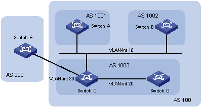
|
Device |
Interface |
IP interface |
AS |
|
Switch A |
Vlan-int 10 |
172.68.10.1/24 |
100 |
|
Switch B |
Vlan-int 10 |
172.68.10.2/24 |
|
|
Switch C |
Vlan-int 10 |
172.68.10.3/24 |
|
|
|
Vlan-int 20 |
172.68.1.1/24 |
|
|
|
Vlan-int 30 |
156.10.1.1/24 |
|
|
Switch D |
Vlan-int 20 |
172.68.1.2/24 |
|
|
Switch E |
Vlan-int 30 |
156.10.1.2/24 |
200 |
Figure 6-5 Diagram for AS confederation
III. Configuration procedure
# Configure Switch A.
[SwitchA] bgp 1001
[SwitchA-bgp] confederation id 100
[SwitchA-bgp] confederation peer-as 1002 1003
[SwitchA-bgp] group confed1002 external
[SwitchA-bgp] peer 172.68.10.2 group confed1002 as-number 1002
[SwitchA-bgp] group confed1003 external
[SwitchA-bgp] peer 172.68.10.3 group confed1003 as-number 1003
# Configure Switch B.
[SwitchB] bgp 1002
[SwitchB-bgp] confederation id 100
[SwitchB-bgp] confederation peer-as 1001 1003
[SwitchB-bgp] group confed1001 external
[SwitchB-bgp] peer 172.68.10.1 group confed1001 as-number 1001
[SwitchB-bgp] group confed1003 external
[SwitchB-bgp] peer 172.68.10.3 group confed1003 as-number 1003
# Configure Switch C.
[SwitchC] bgp 1003
[SwitchC-bgp] confederation id 100
[SwitchC-bgp] confederation peer-as 1001 1002
[SwitchC-bgp] group confed1001 external
[SwitchC-bgp] peer 172.68.10.1 group confed1001 as-number 1001
[SwitchC-bgp] group confed1002 external
[SwitchC-bgp] peer 172.68.10.2 group confed1002 as-number 1002
[SwitchC-bgp] group ebgp200 external
[SwitchC-bgp] peer 156.10.1.2 group ebgp200 as-number 200
[SwitchC-bgp] group ibgp1003 internal
[SwitchC-bgp] peer 172.68.1.2 group ibgp1003
6.9.2 Configuring BGP RR
I. Network requirements
Switch B receives an update packet passing through EBGP, and transfers the packet to Switch C. Switch C is configured as an RR with two clients Switch B and Switch D. After Switch C receives the route update information, it reflects the message to Switch D. You need not establish IBGP connection between Switch B and Switch D because Switch C reflects information from Switch C to Switch D.
II. Network diagram
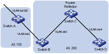
|
Device |
Interface |
IP interface |
AS |
|
Switch A |
Vlan-int 100 |
1.1.1.1/8 |
100 |
|
|
Vlan-int 2 |
192.1.1.1/24 |
|
|
Switch B |
Vlan-int 2 |
192.1.1.2/24 |
200 |
|
|
Vlan-int 3 |
193.1.1.2/24 |
|
|
Switch C |
Vlan-int 3 |
193.1.1.1/24 |
|
|
|
Vlan-int 4 |
194.1.1.1/24 |
|
|
Switch D |
Vlan-int 4 |
194.1.1.2/24 |
Figure 6-6 Diagram for configuring a BGP RR
III. Configuration procedure
1) Configure Switch A.
[SwitchA] interface vlan-interface 2
[SwitchA-Vlan-interface2] ip address 192.1.1.1 255.255.255.0
[SwitchA-Vlan-interface2] interface Vlan-interface 100
[SwitchA-Vlan-interface100] ip address 1.1.1.1 255.0.0.0
[SwitchA-Vlan-interface100] quit
[SwitchA] bgp 100
[SwitchA-bgp] group ex external
[SwitchA-bgp] peer 192.1.1.2 group ex as-number 200
[SwitchA-bgp] network 1.0.0.0 255.0.0.0
2) Configure Switch B.
# Configure VLAN 2.
[SwitchB] interface Vlan-interface 2
[SwitchB-Vlan-interface2] ip address 192.1.1.2 255.255.255.0
# Configure VLAN 3.
[SwitchB] interface Vlan-interface 3
[SwitchB-Vlan-interface3] ip address 193.1.1.2 255.255.255.0
# Configure a BGP peer.
[SwitchB] bgp 200
[SwitchB-bgp] group ex external
[SwitchB-bgp] peer 192.1.1.1 group ex as-number 100
[SwitchB-bgp] group in internal
[SwitchB-bgp] peer 193.1.1.1 group in
3) Configure Switch C.
# Configure VLAN 3.
[SwitchC] interface Vlan-interface 3
[SwitchC-Vlan-interface3] ip address 193.1.1.1 255.255.255.0
# Configure VLAN 4.
[SwitchC] interface vlan-Interface 4
[SwitchC-Vlan-interface4] ip address 194.1.1.1 255.255.255.0
# Configure BGP peers and RR.
[SwitchC] bgp 200
[SwitchC-bgp] group rr internal
[SwitchC-bgp] peer rr reflect-client
[SwitchC-bgp] peer 193.1.1.2 group rr
[SwitchC-bgp] peer 194.1.1.2 group rr
4) Configure Switch D.
# Configure VLAN 4.
[SwitchD] interface vlan-interface 4
[SwitchD-Vlan-interface4] ip address 194.1.1.2 255.255.255.0
# Configure a BGP peer.
[SwitchD] bgp 200
[SwitchD-bgp] group in internal
[SwitchD-bgp] peer 194.1.1.1 group in
Use the display bgp routing-table command to display the BGP routing table on Switch B. Note that Switch B has already known the existence of network 1.0.0.0.
Use the display bgp routing-table command to display the BGP routing table on Switch D. Note that, Switch D knows the existence of network 1.0.0.0, too.
6.9.3 Configuring BGP Routing
I. Network requirements
BGP is applied to all switches, and OSPF is applied to the IGP in AS 200. Switch A is in AS 100, and Switch B, Switch C, and Switch D are in AS 200. EBGP is running between Switch A and Switch B, and between Switch A and Switch C. IBGP is running between Switch B and Switch C, and between Switch B and Switch D.
II. Network diagram
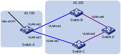
|
Device |
Interface |
IP interface |
AS |
|
Switch A |
Vlan-int 101 |
1.1.1.1/8 |
100 |
|
|
Vlan-int 2 |
192.1.1.1/24 |
|
|
|
Vlan-int 3 |
193.1.1.1/24 |
|
|
Switch B |
Vlan-int 2 |
192.1.1.2/24 |
200 |
|
|
Vlan-int 4 |
194.1.1.2/24 |
|
|
Switch C |
Vlan-int 3 |
193.1.1.2/24 |
|
|
|
Vlan-int 5 |
195.1.1.2/24 |
|
|
Switch D |
Vlan-int 4 |
194.1.1.1/24 |
|
|
|
Vlan-int 5 |
195.1.1.1/24 |
Figure 6-7 Diagram for BGP routing
III. Configuration procedure
1) Configure Switch A.
[SwitchA] interface Vlan-interface 2
[SwitchA-Vlan-interface2] ip address 192.1.1.1 255.255.255.0
[SwitchA] interface Vlan-interface 3
[SwitchA-Vlan-interface3] ip address 193.1.1.1 255.255.255.0
# Enable BGP
[SwitchA] bgp 100
# Specify the destination network for BGP routes.
[SwitchA-bgp] network 1.0.0.0
# Configure BGP peers.
[SwitchA-bgp] group ex192 external
[SwitchA-bgp] peer 192.1.1.2 group ex192 as-number 200
[SwitchA-bgp] group ex193 external
[SwitchA-bgp] peer 193.1.1.2 group ex193 as-number 200
[SwitchA-bgp] quit
# Configure the MED attribute of Switch A.
Create an access control list to permit routing information sourced from the network 1.0.0.0.
[SwitchA] acl number 2000
[SwitchA-acl-basic-2000] rule permit source 1.0.0.0 0.255.255.255
[SwitchA-acl-basic-2000] rule deny source any
Define two routing policies, respectively named apply_med_50 and apply_med_100. The first routing policy apply_med_50 configures the MED attribute as 50 for network 1.0.0.0, and the second one apply_med_100 configures the MED attribute for the network as 100.
[SwitchA] route-policy apply_med_50 permit node 10
[SwitchA-route-policy] if-match acl 2000
[SwitchA-route-policy] apply cost 50
[SwitchA-route-policy] quit
[SwitchA] route-policy apply_med_100 permit node 10
[SwitchA-route-policy] if-match acl 2000
[SwitchA-route-policy] apply cost 100
[SwitchA-route-policy] quit
# Apply apply_med_50 to the outbound routing update of neighbor Switch C (193.1.1.2), and apply apply_med_100 to the outbound routing update of neighbor Switch B (192.1.1.2).
[SwitchA] bgp 100
[SwitchA-bgp] peer ex193 route-policy apply_med_50 export
[SwitchA-bgp] peer ex192 route-policy apply_med_100 export
2) Configure Switch B.
[SwitchB] interface vlan 2
[SwitchB-Vlan-interface2] ip address 192.1.1.2 255.255.255.0
[SwitchB] interface vlan-interface 4
[SwitchB-Vlan-interface4] ip address 194.1.1.2 255.255.255.0
[SwitchB] ospf
[SwitchB-ospf-1] area 0
[SwitchB-ospf-1-area-0.0.0.0] network 194.1.1.0 0.0.0.255
[SwitchB-ospf-1-area-0.0.0.0] network 192.1.1.0 0.0.0.255
[SwitchB] bgp 200
[SwitchB-bgp] undo synchronization
[SwitchB-bgp] group ex external
[SwitchB-bgp] peer 192.1.1.1 group ex as-number 100
[SwitchB-bgp] group in internal
[SwitchB-bgp] peer 194.1.1.1 group in
[SwitchB-bgp] peer 195.1.1.2 group in
3) Configure Switch C.
[SwitchC] interface Vlan-interface 3
[SwitchC-Vlan-interface3] ip address 193.1.1.2 255.255.255.0
[SwitchC] interface vlan-interface 5
[SwitchC-Vlan-interface5] ip address 195.1.1.2 255.255.255.0
[SwitchC] ospf
[SwitchC-ospf-1] area 0
[SwitchC-ospf-1-area-0.0.0.0] network 193.1.1.0 0.0.0.255
[SwitchC-ospf-1-area-0.0.0.0] network 195.1.1.0 0.0.0.255
[SwitchC] bgp 200
[SwitchC-bgp] undo synchronization
[SwitchC-bgp] group ex external
[SwitchC-bgp] peer 193.1.1.1 group ex as-number 100
[SwitchC-bgp] group in internal
[SwitchC-bgp] peer 195.1.1.1 group in
[SwitchC-bgp] peer 194.1.1.2 group in
4) Configure Switch D.
[SwitchD] interface vlan-interface 4
[SwitchD-Vlan-interface4] ip address 194.1.1.1 255.255.255.0
[SwitchD] interface vlan-interface 5
[SwitchD-Vlan-interface5] ip address 195.1.1.1 255.255.255.0
[SwitchD] ospf
[SwitchD-ospf-1] area 0
[SwitchD-ospf-1-area-0.0.0.0] network 194.1.1.0 0.0.0.255
[SwitchD-ospf-1-area-0.0.0.0] network 195.1.1.0 0.0.0.255
[SwitchD-ospf-1-area-0.0.0.0] network 4.0.0.0 0.255.255.255
[SwitchD] bgp 200
[SwitchD-bgp] undo synchronization
[SwitchD-bgp] group in internal
[SwitchD-bgp] peer 195.1.1.2 group in
[SwitchD-bgp] peer 194.1.1.2 group in
l For the configuration to take effect, the reset bgp all command needs to be executed on all the BGP neighbors.
l After the above configuration, because the MED attribute value of the route 1.0.0.0 learned by Switch C is smaller than that of the route 1.0.0.0 learned by Switch B, Switch D will choose the route 1.0.0.0 coming from Switch C.
l If you do not configure MED attribute of Switch A when you configure Switch A but configure the local preference on Switch C as following:
# Configure the local preference of Switch C
l Create ACL 2000 to permit routing information sourced from network 1.0.0.0.
[SwitchC-acl-basic-2000] rule permit source 1.0.0.0 0.255.255.255
[SwitchC-acl-basic-2000] rule deny source any
l Define a routing policy named localpref, and set the local preference of the routes matching with ACL 2000 to 200, and that of those unmatched routes to 100.
[SwitchC] route-policy localpref permit node 10
[SwitchC-route-policy] if-match acl 2000
[SwitchC-route-policy] apply local-preference 200
[SwitchC-route-policy] quit
[SwitchC] route-policy localpref permit node 20
[SwitchC-route-policy] apply local-preference 100
l Apply this routing policy to the inbound traffic flows coming from BGP neighbor 193.1.1.1 (Switch A).
[SwitchC-bgp] peer 193.1.1.1 route-policy localpref import
In this case, because the local preference value of the route 1.0.0.0 learned by Switch C is 200, which is greater than that of the route 1.0.0.0 learned by Switch B (Switch B does not configure the local preference attribute, the default value is 100), Switch D still chooses the route 1.0.0.0 coming from Switch C first.
6.10 Troubleshooting BGP Configuration
Symptom 1: A BGP neighbor relationship cannot be established; that is, the connection with the opposite peer cannot be established.
Solution: The BGP neighbor establishment process requires using port 179 to establish a TCP session and exchanging Open messages correctly. You can follow these steps to solve the problem:
l Check the AS number of the neighbor.
l Check the IP address of the neighbor.
l For an EBGP neighbor not directly connected, verify that the peer ebgp-max-hop command is used.
l Use the ping command to check the TCP connection. As a router may have more than one interface to reach the peer, you should use the ping -a ip-address expanded command to specify a source IP address for sending ping packets.
l If you cannot ping the neighbor device successfully, verify that there is a route to the neighbor in the routing table.
l If you can ping the neighbor device successfully, verify that an ACL is configured to inhibit TCP port 179. If yes, cancel the inhibition of port 179.
Symptom 2: After you use the network command to import the routes discovered by IGP to BGP, the BGP routes cannot be successfully advertised.
Solution: For a route to be successfully imported into BGP, it is required that the route (including the destination network segment and mask) should be consistent with a route in the routing table. For example, a route to the network segment 10.1.1.0/24 exists in the routing table. If a route to 10.0.0.0/8 or other similar segment is imported, an import error will occur. If OSPF is used, when you use the network command to import a bigger network segment, the router will change the route according to the actual interface network segment. This may result in unsuccessful route import or wrong import, and may cause routing error in some network trouble situations.
Chapter 7 IP Routing Policy Configuration
When configuring IP routing policies, go to these sections for information you are interested in:
l IP Routing Policy Configuration
l Displaying and Maintaining IP Routing Policy Configuration
l IP Routing Policy Configuration Example
l Troubleshooting IP Routing Policy
7.1 IP Routing Policy Overview
When a router advertises or receives routing information, it may need to implement some policies to filter routing information in order to advertise or distribute only the routing information meeting the given conditions. A routing protocol (RIP, for example) may need to import the routing information discovered by other protocols like OSPF to enrich its routing knowledge. While importing routing information from other protocols, the router possibly only needs to import the routes meeting the given conditions and set some attributes of the imported routes to make them meet the requirements of this protocol.
To implement a routing policy, you need to define a set of matching rules by specifying the characteristics of the routing information to be filtered. You can set the rules based on such attributes as destination address and source address. The matching rules can be set in advance and then used in routing policies to advertise, receive, or import routes.
7.1.1 Filters
The S7500 series provide five kinds of filters (route-policy, ACL, AS-path, community-list and ip-prefix) for routing protocols reference. The following sections describe these filters.
I. Route-policy
A route-policy is used to match some attributes of route information and the attributes of route information will be set if the conditions are satisfied.
A route policy comprises multiple nodes. Each node is a unit for matching test. Nodes are matched by their node numbers. Each node comprises a set of if-match and apply clauses. The if-match clauses define matching rules. Matching objects are some attributes of routing information. The relationship among the if-match clauses for a node is “AND”. As a result, a matching test against a node is successful only when all the matching conditions specified by all the if-match clauses are satisfied. The apply clauses specify the actions performed after a matching test against the node is successful, that is, configuration to be performed for the attributes of routing information.
The relationships among different nodes in a route-policy are “OR”. The system will examine the nodes in the route-policy in sequence. Once the route passes a node in the route-policy, it will pass the matching test of the route-policy without entering the test of the next node.
II. ACL
Normally, a basic ACL is used to filter routing information. You can specify a range of IP addresses or subnets when defining a basic ACL to match the destination network segment address or the next-hop address of routing information. If an advanced ACL is used, the specified range of source addresses will be used for matching.
III. ip-prefix
An ip-prefix plays a role similar to ACL. But it is more flexible than ACL and easier to understand. When ip-prefix is applied to filtering routing information, its matching object is the destination address information field of routing information.
An ip-prefix is identified by name. An ip-prefix includes multiple items, and each item, identified by an index-number, can independently specify the match range in network prefix form. An index-number specifies the matching sequence in the ip-prefix.
During the matching, the router checks items identified by index-number in ascending order. Once an item is met, the ip-prefix filtering is passed and no other item will be checked.
IV. as-path
An as-path is an access control list of autonomous system paths only used for BGP to match AS paths. A BGP routing information packet includes an AS path field which records the AS paths that the routing information passes through during the exchange process.
V. community-list
A community-list is only used for BGP to match community attributes. A BGP routing information packet contains a community attribute field used to identify a community.
7.1.2 Applications of Routing Policy
The following are main applications of routing policy:
l When a routing protocol advertises or receives routing information, it adopts routing policies to filter routing information, so as to receive or advertise those routing information meeting the given conditions.
l When a routing protocol imports the routes discovered by other protocols, it adopts routing policies to import those routes meeting the given conditions.
In addition, routing policies can also be used to change some route attributes.
7.2 IP Routing Policy Configuration
The configuration of routing policy falls into two parts: filter configuration and application of routing policy.
1) Filter configuration includes:
l Route-policy
l ACL
l IP prefix list
l AS path list
l Community attribute list
& Note:
Refer to the ACL module in this operation manual for ACL configuration.
2) Routing policies are used for:
l Importing routes;
l Advertising or receiving routes.
7.2.1 Configuring a Route Policy
A route-policy comprises multiple nodes. Each node is a unit for matching test, and the nodes will be matched by their sequence numbers.
Each node comprises a set of if-match and apply clauses.
l The if-match clauses define matching rules. The relationship among the if-match clauses for a node is logical “AND”. That is, a matching test against a node is successful only when all the matching conditions specified by the if-match clauses are satisfied.
l The apply clauses specify the actions performed after a matching test against the node is successful, that is, configure some attributes of routing information.
I. Define a route-policy
Follow these steps to define a route-policy:
|
To do... |
Use the command... |
Remarks |
|
Enter system view |
system-view |
— |
|
Define a route-policy and enter route-policy view |
route-policy route-policy-name { permit | deny } node node-number |
Required |
The permit argument specifies that the matching mode for the defined nodes in a route-policy is "permit". In this mode, if a route matches all the if-match clauses of a node, the system executes the apply clauses of the node but does not perform the match test of the next node. If not, the system goes on the match test of the next node.
The deny argument specifies that the matching mode for the defined nodes in a route-policy is "deny". In this mode, no apply clause is executed. If a route matches all the if-match clauses of a node, the system considers that the route fails to pass through the node and does not take the match test of the next node. If not, the system goes on the match test of the next node.
The relationships among different nodes in a route-policy are logical “OR”. The system examines the nodes in a route-policy in sequence. If a route matches a node in the route-policy, which means the route matches the whole route-policy.
By default, no route-policy is defined.
& Note:
Among the nodes defined in a route-policy, at least one node should be in permit mode. When a route-policy applies to filter routing information, a route will be denied as long as its routing information does not match any node. If all the nodes in the route-policy are in deny mode, all routes will be denied by the route-policy.
II. Define if-match Clauses for a Node
An if-match clause defines a matching rule, that is, filtering conditions that routing information should satisfy to pass the match test of the current route-policy. The matching objects are some attributes of routing information.
Follow these steps to define if-match clauses:
|
To do... |
Use the command... |
Remarks |
|
Enter system view |
system-view |
— |
|
Enter route-policy view |
route-policy route-policy-name { permit | deny } node node-number |
— |
|
Define an if-match clause to match the AS path field of BGP routing information |
if-match as-path as-path-number |
Optional |
|
Define an if-match clause to match the community attribute of BGP routing information |
if-match community { basic-community-number [ whole-match ] | adv-community-number } |
Optional |
|
Define an if-match clause to match the destination IP address of routing information |
if-match { acl acl-number | ip-prefix ip-prefix-name } |
Optional |
|
Define an if-match clause to match the next-hop interface of routing information |
if-match interface interface-type interface-number |
Optional |
|
Define an if-match clause to match the next-hop address of routing information |
if-match ip next-hop { acl acl-number | ip-prefix ip-prefix-name } |
Optional |
|
Define an if-match clause to match the cost of routing information |
if-match cost value |
Optional |
|
Define an if-match clause to match the tag field of RIP or OSPF routing information |
if-match tag value |
Optional |
By default, no if-match clause is defined.
& Note:
l The relationship among the if-match clauses for a node specified in the route-policy is logical “AND”. Routing information passes the match test against the node only when it satisfies all the matching conditions specified by the if-match clauses. Once a match is found, the system executes the apply clauses.
l If no if-match clause is defined for a node, all routing information will pass the match test of the node.
III. Define apply Clauses for a Node
The apply clauses specify the actions to be performed after all the filtering conditions of the if-match clauses of a node are satisfied. The actions include modifying some attributes of routing information.
Follow these steps to define apply clauses:
|
To do... |
Use the command... |
Remarks |
|
Enter system view |
system-view |
— |
|
Enter route-policy view |
route-policy route-policy-name { permit | deny } node node-number |
— |
|
Define an apply clause to add the specified AS number before AS path of BGP routing information |
apply as-path as-number-list |
Optional |
|
Define an apply clause to set the community attribute of BGP routing information |
apply community { none | [ aa:nn ] [ no-export-subconfed | no-export | no-advertise ]* [ additive ] } |
Optional |
|
Define an apply clause to set the next-hop address of routing information |
apply ip next-hop ip-address |
Optional |
|
Define an apply clause to import routes into the IS-IS area(s) at specified level(s) |
apply isis [ level-1 | level-2 | level-1-2 ] |
Optional |
|
Define an apply clause to set the local preference of BGP routing information |
apply local-preference local-preference |
Optional |
|
Define an apply clause to set the cost of routing information |
apply cost value |
Optional |
|
Define an apply clause to set the cost type of routing information |
apply cost-type [ internal | external ] |
Optional |
|
Define an apply clause to set the source of BGP routing information |
apply origin { igp | egp as-number | incomplete } |
Optional |
|
Define an apply clause to set the tag field of RIP or OSPF routing information |
apply tag value |
Optional |
By default, no apply clause is defined.
Note that, when IGP routes satisfy the matching conditions specified by a route policy and are advertised to EBGP peers, the cost defined by the apply cost-type internal clause will be used as the cost of IGP routes. The apply cost-type internal command is higher than the default med command but lower than the apply cost command in terms of priority.
7.2.2 Define an IP Prefix List
An ip-prefix (IP prefix list) is identified by name. Each ip-prefix can include multiple items, and each item, identified by an index-number, can independently specify the match range in network prefix form. Index-numbers specify the matching order of the items in the ip-prefix.
Follow these steps to define an IP prefix list:
|
To do... |
Use the command... |
Remarks |
|
Enter system view |
system-view |
— |
|
Define an IP prefix list |
ip ip-prefix ip-prefix-name [ index index-number ] { permit | deny } network len [ greater-equal greater-equal | less-equal less-equal ]* |
Required |
During a matching test, the router checks the items in the ascending order of their index-numbers. Once an item is met, the ip-prefix filtering is passed and no other item will be checked.
& Note:
Among the items defined in an IP prefix list, at least one item should be in permit mode. The items in deny mode can be used to quickly filter out undesired routing information. But if all the items are in deny mode, no route will pass the filter of the IP-prefix list. Therefore, you need to define the permit 0.0.0.0 0 greater-equal 0 less-equal 32 item following multiple deny mode items to permit all other routes to pass through.
7.2.3 Configuring an AS Path List
A BGP routing information packet contains an AS path field, which can be used to filter out the routing information that does not match.
Perform the following configuration in system view.
Follow these steps to configure an AS path list:
|
To do... |
Use the command... |
Remarks |
|
Enter system view |
system-view |
— |
|
Configure an AS path list |
ip as-path-acl acl-number { permit | deny } as-regular-expression |
Required |
By default, no AS path list is defined.
7.2.4 Configuring a Community List
In BGP, community attributes are optional transit attributes. Some community attributes are globally recognized and they are called standard community attributes. Some are for special purposes and they can be customized.
A route can have one or more community attributes. The speaker of multiple community attributes of a route can act based on one, multiple or all attributes. A router can decide whether to change community attributes before forwarding a route to peers.
A community list is used to identify community information. It falls in to two types: basic community list and advanced community list. The former ranges from 1 to 99, and the latter ranges from 100 to 199.
Follow these steps to configure a community list:
|
To do... |
Use the command... |
Remarks |
|
Enter system view |
system-view |
— |
|
Configure a basic community list |
ip community-list basic-comm-list-number { permit | deny } [ aa:nn | internet | no-export-subconfed | no-advertise | no-export ]* |
Optional |
|
Configure an advanced community list |
ip community-list adv-comm-list-number { permit | deny } comm-regular-expression |
Optional |
By default, no BGP community list is defined.
7.2.5 Applying a Routing Policy to Import Routes
A routing protocol can import the routes discovered by other routing protocols to enrich its route knowledge. During route import, you can adopt a route-policy to filter routing information, so as to import only needed routes. If the destination routing protocol cannot directly use the cost of the source routing protocol, you should specify a cost for the imported routes.
& Note:
The import-route command (used to import routes) is somewhat different in form in different routing protocol views. Refer to the import-route command description under routing protocols in the command manual.
7.2.6 Applying a Routing Policy to Receive or Advertise Routes
& Note:
The filter-policy command (used to apply a routing policy to receive or advertise routes) is somewhat different in form in different routing protocol views. Refer to the filter-policy command description under routing protocols in the command manual.
7.3 Displaying and Maintaining IP Routing Policy Configuration
|
To do... |
Use the command... |
Remarks |
|
Display route-policy information |
display route-policy [ route-policy-name ] |
Available in any view |
|
Display information about the specified AS path ACL |
display ip as-path-acl [ acl-number ] |
|
|
Display information about the specified address prefix list |
display ip ip-prefix [ ip-prefix-name ] |
|
|
Display information about the specified community list |
display ip community-list [ basic-comm-list-number | adv-comm-list-number ] |
7.4 IP Routing Policy Configuration Example
7.4.1 Filtering Routing Information
I. Network requirements
l As shown in Figure 7-1, Switch A communicates with Switch B. Both switches enable the OSPF protocol. Switch A’s router ID is 1.1.1.1 and Switch B’s is 2.2.2.2.
l Configure OSPF routing process on Switch A: configuring and importing three static routes.
l Configure a routing policy on Switch A to filter imported static routes. In this example, the routes in 20.0.0.0 and 40.0.0.0 network segments can be imported, but those in 30.0.0.0 network segment will be filtered out.
II. Network diagram
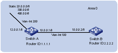
Figure 7-1 Networking diagram for filtering routing information received
III. Configuration procedure
1) Configure Switch A:
# Configure the IP addresses of the interfaces.
<SwitchA> system-view
[SwitchA] interface vlan-interface 100
[SwitchA-Vlan-interface100] ip address 10.0.0.1 255.0.0.0
[SwitchA-Vlan-interface100] quit
[SwitchA] interface vlan-interface 200
[SwitchA-Vlan-interface200] ip address 12.0.0.1 255.0.0.0
[SwitchA-Vlan-interface200] quit
# Configure three static routes.
[SwitchA] ip route-static 20.0.0.1 255.0.0.0 12.0.0.2
[SwitchA] ip route-static 30.0.0.1 255.0.0.0 12.0.0.2
[SwitchA] ip route-static 40.0.0.1 255.0.0.0 12.0.0.2
# Enable the OSPF protocol and specify the ID of the area to which the interface 10.0.0.1 belongs.
<SwitchA> system-view
[SwitchA] router id 1.1.1.1
[SwitchA] ospf
[SwitchA-ospf-1] area 0
[SwitchA-ospf-1-area-0.0.0.0] network 10.0.0.0 0.255.255.255
[SwitchA-ospf-1-area-0.0.0.0] quit
[SwitchA-ospf-1]quit
# Configure an ACL.
[SwitchA] acl number 2000
[SwitchA-acl-basic-2000] rule deny source 30.0.0.0 0.255.255.255
[SwitchA-acl-basic-2000] rule permit source any
[SwitchA-acl-basic-2000] quit
# Configure a route-policy.
[SwitchA] route-policy ospf permit node 10
[SwitchA -route-policy] if-match acl 2000
[SwitchA -route-policy] quit
# Apply route policy when the static routes are imported.
[SwitchA] ospf
[SwitchA-ospf-1] import-route static route-policy ospf
2) Configure Switch B:
# Configure the IP address of the interface.
<SwitchB> system-view
[SwitchB] interface vlan-interface 100
[SwitchB-Vlan-interface100] ip address 10.0.0.2 255.0.0.0
[SwitchB-Vlan-interface100] quit
# Enable the OSPF protocol and specify the ID of the area to which the interface 10.0.0.2 belongs.
[SwitchB] router id 2.2.2.2
[SwitchB] ospf
[SwitchB-ospf-1] area 0
[SwitchB-ospf-1-area-0.0.0.0] network 10.0.0.0 0.255.255.255
[SwitchB-ospf-1-area-0.0.0.0] quit
[SwitchB-ospf-1] quit
7.5 Troubleshooting IP Routing Policy
Symptom: Routing information cannot be filtered when the routing protocol runs normally.
Solution: Check to see the following requirements are satisfied.
At least one node in a route-policy should be in permit mode. When a route-policy is used to filter routing information, if a route fails to pass the match test against any node, the route information will not pass the filtering of the route-policy. When all the nodes in the route-policy are in the deny mode, no routing information will pass the filtering of the route-policy.
At least one item in an ip-prefix list should be in permit mode. The items in deny mode can be defined first to rapidly filter out the routing information not meeting the conditions. However, if all the items are in the deny mode, no route will pass the filtering of the ip-prefix list. Therefore, you need to define a permit 0.0.0.0 0 greater-equal 0 less-equal 32 item following multiple deny mode items to permit all other routes to pass through (if less-equal 32 is not specified, only the default route will be matched).
Chapter 8 Route Capacity Configuration
When configuring route capacity, go to these sections for information you are interested in:
l Route Capacity Configuration
l Displaying and Maintaining Route Capacity Configuration
8.1 Route Capacity Overview
8.1.1 Introduction
In actual networking applications, there are a large number of routes, especially OSPF routes, IS-IS routes and BGP routes, in the routing table. If the routing table occupies too much memory, the switch performance will decline.
To solve this problem, the S7500 series provide a mechanism to control the size of the routing table; that is, monitoring the free memory in the system to determine whether to add new routes to the routing table and whether to keep the connection of a routing protocol.
![]() Caution:
Caution:
Generally, the default system configuration meets the requirements. To avoid decreasing system stability and availability due to improper configuration, you are not recommended to modify the configuration.
8.1.2 Route Capacity Limitation on the S7500 Series
Huge routing tables are usually caused by IS-IS, BGP and OSPF routes. Therefore, the route capacity limitation implemented by a S7500 switch applies to IS-IS, BGP and OSPF routes only but not to static routes and other dynamic routing protocols.
When the free memory of a switch is equal to or lower than the lower limit, IS-IS, BGP or OSPF connection will be disconnected and corresponding routes will be removed from the routing table.
The system periodically checks the free memory. If automatic protocol connection recovery is enabled, when the free memory of the switch restores to a value larger than the safety value, the switch automatically re-establishes the IS-IS, BGP or OSPF connection. If the automatic protocol connection recovery function is disabled, the switch will not re-establish the disconnected IS-IS, BGP or OSPF connection even when the free memory restores to a value larger than the safety value.
8.2 Route Capacity Configuration
Route capacity configuration includes:
l Setting the lower limit and the safety value of switch memory
l Enabling/disabling the switch to recover the disconnected routing protocol automatically
8.2.1 Setting the Lower Limit and the Safety Value of the Switch Memory
Follow these steps to set the lower limit and the safety value of switch memory:
|
To do... |
Use the command... |
Remarks |
|
Enter system view |
system-view |
— |
|
Set the lower limit and the safety value of switch memory |
memory { safety safety-value | limit limit-value }* |
Optional |
& Note:
The safety-value must be greater than the limit-value.
8.2.2 Enabling/Disabling Automatic Protocol Connection Recovery
Follow these steps to enable/disable automatic protocol recovery:
|
To do... |
Use the command... |
Remarks |
|
Enter system view |
system-view |
— |
|
Enable automatic protocol recovery |
memory auto-establish enable |
Optional By default, automatic protocol connection recovery is enabled. |
|
Disable automatic protocol connection recovery |
memory auto-establish disable |
Optional |
![]() Caution:
Caution:
If automatic protocol recovery is disabled, the broken OSPF, ISIS, or BGP connection will not recover even when the value of free memory exceeds the safety value. Therefore, do not disable this function if not necessary.
8.3 Displaying and Maintaining Route Capacity Configuration
|
To do... |
Use the command... |
Remarks |
|
Display memory occupancy of a switch |
display memory [ slot slotnumber ] |
Available in any view |
|
Display the memory setting and status information related to route capacity |
display memory limit |