- Table of Contents
-
- H3C S7500 Series Operation Manual(Release 3100 Series)-(V1.04)
- 00-1Cover
- 00-2Overview
- 01-CLI Configuration
- 02-Login Configuration
- 03-Configuration File Management Configuration
- 04-VLAN Configuration
- 05-Extended VLAN Application Configuration
- 06-IP Address-IP Performance-IPX Configuration
- 07-GVRP Configuration
- 08-QinQ Configuration
- 09-Port Basic Configuration
- 10-Link Aggregation Configuration
- 11-Port Isolation Configuration
- 12-Port Binding Configuration
- 13-DLDP Configuration
- 14-MAC Address Table Configuration
- 15-MSTP Configuration
- 16-Routing Protocol Configuration
- 17-Multicast Configuration
- 18-802.1x Configuration
- 19-AAA-RADIUS-HWTACACS-EAD Configuration
- 20-Traffic Accounting Configuration
- 21-VRRP-HA Configuration
- 22-ARP Configuration
- 23-DHCP Configuration
- 24-ACL Configuration
- 25-QoS Configuration
- 26-Mirroring Configuration
- 27-Cluster Configuration
- 28-PoE Configuration
- 29-UDP-Helper Configuration
- 30-SNMP-RMON Configuration
- 31-NTP Configuration
- 32-SSH Terminal Service Configuration
- 33-File System Management Configuration
- 34-FTP and TFTP Configuration
- 35-Information Center Configuration
- 36-DNS Configuration
- 37-System Maintenance and Debugging Configuration
- 38-HWPing Configuration
- 39-RRPP Configuration
- 40-NAT-Netstream-Policy Routing Configuration
- 41-Telnet Protection Configuration
- 42-Hardware-Dependent Software Configuration
- Related Documents
-
| Title | Size | Download |
|---|---|---|
| 06-IP Address-IP Performance-IPX Configuration | 279 KB |
Table of Contents
Chapter 1 IP Address Configuration
1.1.1 IP Address Classification and Representation
1.2 Configuring IP Address(es) for a VLAN Interface
1.3 Displaying and Maintaining IP Address Configuration
1.4 IP Address Configuration Example
1.5 Troubleshooting IP Address Configuration
Chapter 2 IP Performance Configuration
2.1.1 Introduction to TCP Attributes
2.2 IP Performance Configuration Task List
2.3 Configuring TCP Attributes
2.4 Configuring to Send Special IP Packets to CPU
2.5 Configuring to Forward Layer 3 Broadcast Packets
2.6 Displaying and Maintaining IP Performance Configuration
2.7 Troubleshooting IP Performance Configuration
3.1.1 Routing Information Protocol
3.1.2 Service Advertising Protocol
3.2.1 IPX Configuration Task List
3.2.6 Configuring IPX Forwarding
3.3 Displaying and Maintaining IPX Configuration
3.5 Troubleshooting IPX Configuration
Chapter 1 IP Address Configuration
When configuring IP address, go to these sections for information you are interested in:
l Configuring IP Address(es) for a VLAN Interface
l Displaying and Maintaining IP Address Configuration
l IP Address Configuration Example
l Troubleshooting IP Address Configuration
1.1 IP Address Overview
1.1.1 IP Address Classification and Representation
An IP address is a 32-bit address allocated to a device connected to the Internet. It consists of two fields: net-id and host-id. To facilitate IP address management, IP addresses are divided into five classes, as shown in Figure 1-1.
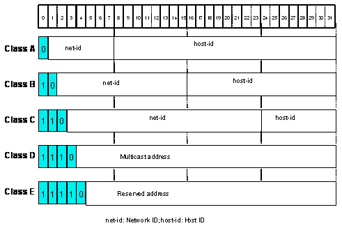
Figure 1-1 Five classes of IP addresses
Class A, Class B, and Class C IP addresses are unicast addresses. Class D IP addresses are multicast addresses and Class E addresses are reserved for future special use. The first three types are commonly used.
IP addresses are in the dotted decimal notation. Each IP address contains four decimal integers (separated from each other using “.”), with each integer corresponding to one byte (for example, 10.110.50.101).
Some IP addresses are reserved for special use. The IP address ranges that can be used by users are listed in Table 1-1.
Table 1-1 Classes and ranges of IP addresses
|
Network type |
Address range |
IP network range |
Description |
|
A |
0.0.0.0 to 127.255.255.255 |
1.0.0.0 to 126.0.0.0 |
l An IP address with all 0s host ID is a network address and is used for network routing. l An IP address with all 1s host ID is a broadcast address and is used for broadcast to all hosts on the network. l The IP address 0.0.0.0 is used by hosts when they are booted but are not used afterward. l An IP address with all 0s network ID represents a specific host on the local network and can be used as a source address but cannot be used as a destination address. l All the IP addresses in the format of 127.X.Y.Z are reserved for loopback test and the packets sent to these addresses will not be output to lines; instead, they are processed internally and regarded as incoming packets. |
|
B |
128.0.0.0 to 191.255.255.255 |
128.0.0.0 to 191.255.0.0 |
l An IP address with all 0s host ID is a network address and is used for network routing. l An IP address with all 1s host ID is a broadcast address and is used for broadcast to all hosts on the network. |
|
C |
192.0.0.0 to 223.255.255.255 |
192.0.0.0 to 223.255.255.0 |
l An IP address with all 0s host ID is a network address and is used for network routing. l An IP address with all 1s host ID is a broadcast address and is used for broadcast to all hosts on the network. |
|
D |
224.0.0.0 to 239.255.255.255 |
None |
Class D addresses are multicast addresses. |
|
E |
240.0.0.0 to 255.255.255.254 |
None |
These IP addresses are reserved for future use. |
|
Others |
255.255.255.255 |
255.255.255.255 |
255.255.255.255 is used as a LAN broadcast address. |
1.1.2 Subnet and Mask
The traditional IP address classification method wastes IP addresses greatly. In order to make full use of the available IP addresses, the concepts of mask and subnet were introduced.
A mask is a 32-bit number corresponding to an IP address. The number consists of 1s and 0s. A mask is defined as follows: the bits of the network number and subnet number are set to 1, and the bits of the host number are set to 0. The mask divides an IP address into two parts: subnet address and host address. In an IP address, the part corresponding to the "1" bits in the mask is the subnet address, and the part corresponding to the remaining "0" bits in the mask is the host address. If there is no subnet division, the subnet mask uses the default value and the length of 1s in the mask is equal to the net-id length. Therefore, for IP addresses of classes A, B and C, the default values of the corresponding subnet masks are 255.0.0.0, 255.255.0.0 and 255.255.255.0 respectively.
The mask can be used to divide a Class A network containing more than 16,000,000 hosts or a Class B network containing more than 60,000 hosts into multiple small networks. Each small network is called a subnet. For example, for the Class B network address 138.38.0.0, the mask 255.255.224.0 can be used to divide the network into eight subnets: 138.38.0.0, 138.38.32.0, 138.38.64.0, 138.38.96.0, 138.38.128.0, 138.38.160.0, 138.38.192.0 and 138.38.224.0 (see Figure 1-2). Each subnet can contain more than 8,000 hosts.
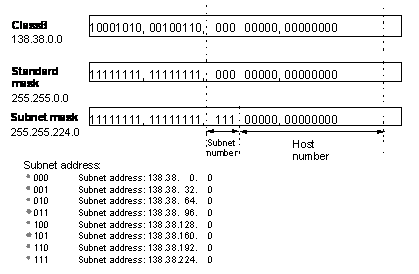
Figure 1-2 Subnet division of the IP address
1.2 Configuring IP Address(es) for a VLAN Interface
You can only configure an IP address for the VLAN interface using a corresponding command. Generally, it is enough to configure one IP address for a VLAN interface. However, you can configure up to five IP addresses for a VLAN interface so that the interface can be connected to several subnets. Among these IP addresses, one is the primary IP address and the others are secondary ones.
Follow these steps to configure IP address(es) for a VLAN interface:
|
To do… |
Use the command… |
Remarks |
|
Enter system view |
system-view |
— |
|
Enter VLAN interface view |
interface Vlan-interface vlan-id |
— |
|
Configure an IP address for a VLAN interface |
ip address ip-address { mask | mask-length } [ sub ] |
Required By default, a VLAN interface has no IP address. |
1.3 Displaying and Maintaining IP Address Configuration
|
To do… |
Use the command… |
Remarks |
|
View VLAN interface information |
display ip interface [ brief ] [ interface-type [ interface-number ] ] |
Available in any view |
1.4 IP Address Configuration Example
I. Network requirements
Set the IP address and subnet mask of VLAN interface 1 to 129.2.2.1 and 255.255.255.0 respectively.
II. Network diagram
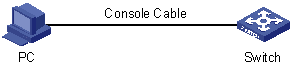
Figure 1-3 IP address configuration
III. Configuration procedure
# Configure an IP address for VLAN interface 1.
<H3C> system-view
[H3C] interface Vlan-interface 1
[H3C-Vlan-interface1] ip address 129.2.2.1 255.255.255.0
1.5 Troubleshooting IP Address Configuration
Symptom: The switch cannot ping through the directly connected host.
Solution: You can perform troubleshooting as follows:
l Check the configuration of the switch, and then use the display arp command to check whether the host has a corresponding ARP entry in the ARP table maintained by the Switch.
l Check the VLAN that includes the switch port connecting the host. Check whether the VLAN has been configured with a VLAN interface. Then check whether the IP addresses of the VLAN interface and the host are on the same network segment.
l If the configuration is correct, enable ARP debugging on the switch, and check whether the switch can correctly send and receive ARP packets. If it can only send but cannot receive ARP packets, errors may occur at the Ethernet physical layer.
Chapter 2 IP Performance Configuration
When configuring IP performance, go to these sections for information you are interested in:
l IP Performance Configuration Task List
l Configuring to Send Special IP Packets to CPU
l Configuring to Forward Layer 3 Broadcast Packets
l Displaying and Maintaining IP Performance Configuration
l Troubleshooting IP Performance Configuration
2.1 IP Performance Overview
2.1.1 Introduction to TCP Attributes
IP performance configuration refers to TCP attribute configuration. The TCP attributes that can be configured include:
l synwait timer: This timer is started when TCP sends a syn packet. If no response packet is received before the timer times out, the TCP connection will be terminated. The timeout of the synwait timer ranges from 2 to 600 seconds and is 75 seconds by default.
l finwait timer: This timer is started when the TCP connection turns from the FIN_WAIT_1 state to the FIN_WAIT_2 state. If no FIN packet is received before the timer times out, the TCP connection will be terminated. The timeout of the finwait timer ranges from 76 to 3,600 seconds and is 675 seconds by default.
l The connection-oriented socket receive/send buffer size ranges from 1 to 32 KB and is 8 KB by default.
2.1.2 Introduction to FIB
Every switch stores a forwarding information base (FIB). An FIB is used to store the forwarding information of the switch and guide Layer 3 packet forwarding.
You can know the forwarding information of the switch through the FIB table. Each FIB entry includes: destination address/mask length, next hop, current flag, timestamp, and outbound interface.
When the switch is running normally, the contents of the FIB and the routing table are the same. For routing and routing tables, refer to the Routing Protocol module of this manual.
2.2 IP Performance Configuration Task List
Complete the following tasks to configure IP performance:
|
Task |
Remarks |
|
Required |
|
|
Required |
|
|
Required |
2.3 Configuring TCP Attributes
Follow these steps to configure TCP attributes:
|
To do… |
Use the command… |
Remarks |
|
Enter system view |
system-view |
— |
|
Configure timeout time for the synwait timer in TCP |
tcp timer syn-timeout time-value |
Required The default value is 75 seconds. |
|
Configure timeout time for the FIN_WAIT_2 timer in TCP |
tcp timer fin-timeout time-value |
Required The default value is 675 seconds. |
|
Configure the socket receiving/sending buffer size of TCP |
tcp window window-size |
Required By default, the size of the socket receiving and sending buffers is 8 KB. |
2.4 Configuring to Send Special IP Packets to CPU
Usually the switch sends TTL timeout packets and Unreachable packets to the CPU in the process of forwarding IP packets. The CPU processes these special packets after receiving them. Incorrect configuration and malicious attacks will cause heavy CPU load. You can perform the following configuration to configure not to send corresponding packets to the CPU in order to ensure normal running.
Follow these steps to configure to send special IP packets to CPU:
|
To do… |
Use the command… |
Remarks |
|
Enter system view |
system-view |
— |
|
Configure to send TTL timeout packets and unreachable packets to CPU |
ip { ttl-expires | unreachables } |
Required By default, Unreachable packets are not sent to the CPU, while TTL timeout packets are sent to the CPU |
2.5 Configuring to Forward Layer 3 Broadcast Packets
Broadcast packets include total-net broadcast packets and directly-connected broadcast packets. The destination IP address of a total-net broadcast packet is all 1s (255.255.255.255) or all 0s. A directly-connected broadcast packet is a packet whose destination IP address is the network broadcast address of a subnet, but the source IP address is not in the subnet segment. When a switch forwards this kind of packet, the switch cannot tell whether the packet is a broadcast packet if the switch is not connected with the subnet.
If a broadcast packet reaches the destination network after being forwarded by the switch, the switch will receive the broadcast packet, because the switch also belongs to the subnet. Because the VLAN of the switch isolates the broadcast domain, the switch will stop forwarding the packet to the network. Using the following configuration tasks, you can choose to forward the broadcast packet to the network for broadcast.
Follow these steps to configure to forward layer 3 broadcast packets in system view:
|
To do… |
Use the command… |
Remarks |
|
Enter system view |
system-view |
— |
|
Configure to forward Layer 3 broadcast packets |
ip forward-broadcast |
Required By default, the switch does not forward Layer 3 broadcast packets. |
2.6 Displaying and Maintaining IP Performance Configuration
|
To do… |
Use the command… |
Remarks |
|
View TCP connection status |
display tcp status |
Available in any view |
|
View TCP connection statistics |
display tcp statistics |
|
|
View UDP traffic statistics |
display udp statistics |
|
|
View IP traffic statistics |
display ip statistics |
|
|
View ICMP traffic statistics |
display icmp statistics |
|
|
View the current socket information of the system |
display ip socket [ socktype sock-type ] [ task-id socket-id ] |
|
|
View the FIB entries |
display fib |
|
|
View the FIB entry matching the specified destination IP address |
display fib ip_address1 [ { mask1 | mask-length1 } [ ip_address2 { mask2 | mask-length2 } | longer ] | longer ] |
|
|
View the FIB entries that pass the filtering of the specified ACL |
display fib acl number |
|
|
View the FIB entries that are output from the buffer according to the regular expression and are related to the specific character string |
display fib | { begin | include | exclude } text |
|
|
View the FIB entries that pass the filtering of the specified prefix list |
display fib ip-prefix listname |
|
|
View the total number of FIB entries |
display fib statistics |
|
|
Clear IP traffic statistics |
reset ip statistics |
Available in user view |
|
Clear TCP traffic statistics |
reset tcp statistics |
|
|
Clear UDP traffic statistics |
reset udp statistics |
2.7 Troubleshooting IP Performance Configuration
Symptom: IP packets are forwarded normally, but TCP and UDP cannot work normally.
Solution: Enable the corresponding debugging information output to view the debugging information.
l Use the display command to display the IP performance and check whether the PC runs normally.
l Use the terminal debugging command to enable debugging information to be output to the console.
l Use the debugging udp packet command to enable the UDP debugging to track UDP packets.
<H3C> terminal debugging
<H3C> debugging udp packet
The UDP packets are shown in the following format:
UDP output packet:
Source IP address:202.38.160.1
Source port:1024
Destination IP Address 202.38.160.1
Destination port: 4296
l Use the debugging tcp packet command to enable the TCP debugging to track TCP packets.
<H3C> terminal debugging
<H3C> debugging tcp packet
Then the TCP packets received or sent will be displayed in the following format in real time:
TCP output packet:
Source IP address:202.38.160.1
Source port:1024
Destination IP Address 202.38.160.1
Destination port: 4296
Sequence number :4185089
Ack number: 0
Flag :SYN
Packet length :60
Data offset: 10
Chapter 3 IPX Configuration
When configuring IPX, go to these sections for information you are interested in:
l Displaying and Maintaining IPX Configuration
l Troubleshooting IPX Configuration
3.1 IPX Protocol Overview
The internetwork packet exchange (IPX) protocol is a network layer protocol in the NetWare protocol suite. IPX's position in the Novell Netware protocol is similar to that of IP in the TCP/IP protocol suite. IPX can address, route and forward packets.
IPX is a connectionless protocol. Though an IPX packet contains a destination IPX address in addition to the data, IPX does not ensure that packets are forwarded to the destination successfully. Packet forwarding results and connection control must be provided by protocols above IPX. In IPX, each IPX packet is considered as an independent entity that has no logical or sequential relationship with any other IPX packets.
IPX and IP use different address structure. An IPX address comprises two parts: the network number and the node address; it is in the format of “network.node”.
A network number identifies the network where a site is located. It is four bytes long and expressed by eight hexadecimal numbers. A node address identifies a node on the network. Like an MAC address, it is six bytes long and comprises three 2-byte numbers (separated from each other using “-”). The node address cannot be a broadcast or multicast address. For example, in the IPX address bc.0-0cb-47, bc (or 000000bc) is the network number and 0-0cb-47 (0000-00cb-0047) is the node address. You can also write an IPX address in the form of N.H-H-H, where N is the network number and H-H-H is the node address.
3.1.1 Routing Information Protocol
IPX uses the routing information protocol (RIP) to maintain and advertise dynamic routing information. With IPX enabled, the switch exchanges routing information with other neighbors through RIP to maintain an inter-network routing information database (also known as a routing table) to accommodate to network changes. When the switch receives a packet, it looks up the routing table for the next site and forwards a packet (if available). The routing information can be configured statically or collected dynamically.
This chapter describes RIP in IPX. For the RIP configurations on an IP network, refer to the Routing Protocol module of this manual.
3.1.2 Service Advertising Protocol
IPX uses service advertising protocol (SAP) to maintain and advertise dynamic service information. SAP advertises the services provided by servers and their addresses as well. With SAP, a server broadcasts its services when it starts up and the termination of the services when it is shut down.
With IPX enabled, the switch creates and maintains an inter-network service information database (or the service information table) through SAP. It helps you learn what services are available on the networks and where they are provided. The servers periodically broadcast their services and addresses to the networks directly connected to them. However, you cannot use such information directly. Instead, the information is collected by the SAP agents of the switches on the networks and saved in their server information tables.
3.2 Configuring IPX
3.2.1 IPX Configuration Task List
Complete the following tasks to configure IPX:
|
Task |
Remarks |
|
Required |
|
|
Required |
|
|
Required |
|
|
Required |
|
|
Required |
3.2.2 Configuring Basic IPX
Follow these steps to configure basic IPX:
|
To do… |
Use the command… |
Remarks |
|
Enter system view |
system-view |
— |
|
Enable IPX |
ipx enable |
Required Disabled by default. |
|
Enter VLAN interface view |
interface Vlan-interface vlan-id |
— |
|
Configure an IPX network number for the VLAN interface |
ipx network network |
Required By default, the system does not assign network numbers to VLAN interfaces. That is, IPX is disabled on all VLAN interfaces. |
& Note:
l After the undo ipx enable command is executed, the IPX configurations are removed and cannot be recovered using the ipx enable command.
l After IPX is enabled, you must assign a network number to a VLAN interface to enable IPX on this VLAN interface. One network number can be assigned to only one VLAN interface.
l If the IPX network number of a VLAN interface is deleted, the IPX configuration and static routing information of this VLAN interface will be deleted at the same time.
3.2.3 Configuring IPX Routing
I. Configuring IPX static routes
Follow these steps to configure IPX static routes:
|
To do… |
Use the command… |
Remarks |
|
Enter system view |
system-view |
— |
|
Enable IPX |
ipx enable |
Required Disabled by default. |
|
Enter VLAN interface view |
interface Vlan-interface vlan-id |
— |
|
Configure an IPX network number for the VLAN interface |
ipx network network |
Required By default, the system does not assign network numbers to VLAN interfaces. That is, IPX is disabled on all VLAN interfaces. |
|
Exit VLAN interface view |
quit |
— |
|
Configure IPX static routes |
ipx route-static network network.node [ preference value ] [ tick ticks hop hops ] |
Optional The IPX static routes whose destination network number is 0xFFFFFFFE are default routes. |
II. Configuring IPX route limit
In IPX, you can configure, in the routing table, the maximum number of the dynamic routes and equivalent routes to the same destination. These two limit settings are independent of each other.
When the number of the dynamic routes to the same destination address reaches the limit, new dynamic routes are dropped directly rather than added into the routing table. When the new setting is smaller than the old value, the switch, however, does not delete the excess route entries. These route entries age out automatically.
If the newly configured limit is smaller than the number of current active routes, the system deactivates the excess active routes. If the newly configured limit is greater than the number of current active routes, the system activates the existing routes that are equivalent to them until the limit is reached.
Follow these steps to configure the IPX route limit:
|
To do… |
Use the command… |
Remarks |
|
Enter system view |
system-view |
— |
|
Enable IPX |
ipx enable |
Required Disabled by default. |
|
Configure the maximum number of dynamic routes to the same destination |
ipx route max-reserve-path paths |
Optional By default, the maximum number of dynamic routes to the same destination is 4. |
|
Configure the maximum number of equivalent routes to the same destination |
ipx route load-balance-path paths |
Optional By default, the maximum number of equivalent routes to the same destination is 1. |
3.2.4 Configuring IPX RIP
After IPX is enabled on VLAN interfaces, the system automatically enables RIP. You can configure IPX RIP parameters as needed.
Follow these steps to configure IPX RIP:
|
To do… |
Use the command… |
Remarks |
|
Enter system view |
system-view |
— |
|
Enable IPX |
ipx enable |
Required Disabled by default. |
|
Configure the update interval of IPX RIP |
ipx rip timer update seconds |
Optional By default, the update interval of IPX RIP is 60 seconds. |
|
Configure the aging interval of IPX RIP |
ipx rip multiplier multiplier |
Optional By default, the aging interval is three times the RIP updating interval. |
|
Configure IPX RIP to import static routes |
ipx rip import-route static |
Optional By default, IPX RIP does not import static routes. |
|
Enter VLAN interface view |
interface Vlan-interface vlan-id |
— |
|
Configure an IPX network number for the VLAN interface |
ipx network network |
Required By default, the system does not assign network numbers to VLAN interfaces. That is, IPX is disabled on all VLAN interfaces. |
|
Configure the size of IPX RIP update packets |
ipx rip mtu bytes |
Optional By default, the maximum size of IPX RIP update packets is 432 bytes. |
|
Configure the IPX packet forwarding delay on a VLAN interface |
ipx tick ticks |
Optional By default, the forwarding delay on the VLAN interface is one tick. |
After IPX RIP is enabled, the switch broadcasts IPX RIP update packets periodically. You can configure the update interval of IPX RIP as required. Note that for the synchronization of routing tables, all the switches on the network must have the same RIP update interval.
The aging interval of IPX RIP is a multiple of the IPX RIP update interval. You can set multiple update intervals as an aging interval. If a routing entry is not updated at the expiry of one RIP aging interval, it will be deleted from the routing table. At the same time, its associated dynamic service entry will be deleted from the service information table.
By default, the maximum IPX RIP update packet size is 432 bytes. Considering the 32 bytes for the total length of IPX and RIP headers, each update packet can carry up to 50 eight-byte routing entries by default.
IPX RIP uses “hops” and “ticks” to measure the distance to a destination network and route packets. The hop count is incremented by 1 every time the packet is forwarded. Ticks (1 tick = 1/18 seconds) indicate the delay that a VLAN interface experiences to forward an IPX packet. A longer delay means slower forwarding whereas a shorter delay means faster forwarding.
By importing routes, different routing protocols can share their routing information mutually. Note that IPX RIP imports only active static routes; inactive static routes are neither imported nor forwarded.
3.2.5 Configuring IPX SAP
I. Enabling IPX SAP
After IPX is enabled on VLAN interfaces, the system enables SAP automatically. You can configure SAP parameters and service information as needed.
Follow these steps to configure IPX SAP:
|
To do… |
Use the command… |
Remarks |
|
Enter system view |
system-view |
— |
|
Enable IPX |
ipx enable |
Required Disabled by default. |
|
Enter VLAN interface view |
interface Vlan-interface vlan-id |
— |
|
Configure an IPX network number for the VLAN interface |
ipx network network |
Required By default, the system does not assign network numbers to VLAN interfaces. That is, IPX is disabled on all the VLAN interfaces. |
|
Enable IPX SAP |
undo ipx sap disable |
Required By default, SAP is enabled as soon as IPX is enabled on the VLAN interface. |
II. Configuring IPX SAP
In a large network, one IPX SAP broadcast consumes enormous bandwidth resources. By configuring an appropriate SAP update interval, you can reduce bandwidth waste. Make sure that all servers and switches on the network have the same SAP update interval. Otherwise, the switches mistake an operating server for a failed one.
The aging interval of IPX SAP is a multiple of the IPX RIP update interval. You can set multiple update intervals as an aging interval.
Follow these steps to configure IPX SAP:
|
To do… |
Use the command… |
Remarks |
|
Enter system view |
system-view |
— |
|
Enable IPX |
ipx enable |
Required Disabled by default. |
|
Configure the update interval of IPX SAP |
ipx sap timer update seconds |
Optional By default, the update interval of IPX SAP is 60 seconds. |
|
Configure the aging interval of IPX SAP |
ipx sap multiplier multiplier |
Optional By default, an IPX SAP service entry is deleted if it is not updated within three update intervals. |
|
Enter VLAN interface view |
interface Vlan-interface vlan-id |
— |
|
Configure an IPX network number for the VLAN interface |
ipx network network |
Required By default, the system does not assign network numbers to VLAN interfaces. That is, IPX is disabled on all VLAN interfaces. |
|
Enable IPX SAP |
undo ipx sap disable |
Required By default, SAP is enabled as soon as IPX is enabled on the VLAN interface. |
|
Configure the size of IPX SAP update packets |
ipx sap mtu bytes |
Optional By default, the maximum size of an IPX SAP update packet is 480 bytes. Each SAP update packet can carry up to seven sets of 64-byte service information. |
III. Configuring IPX GNS
Get nearest server (GNS) is a type of SAP message broadcasted by SAP-enabled NetWare clients. To the GNS requests, NetWare servers respond with GNS messages.
If a NetWare server is available on the network segment to which the client is connected, the server responds to its request. If no NetWare server is available on the segment, the switch responds to such messages.
You can enable the switch to handle a SAP GNS request in one of the following ways:
l Respond with the information of the nearest server (the server with the smallest hop count in the service information table on the switch).
l Respond with the information of one server that is picked out from all the known servers through round-robin polling.
l Respond depending on whether SAP GNS reply is enabled on the VLAN interface.
Follow these steps to configure IPX GNS:
|
To do… |
Use the command… |
Remarks |
|
|
Enter system view |
system-view |
— |
|
|
Enable IPX |
ipx enable |
Required Disabled by default. |
|
|
Configure GNS reply of IPX SAP |
Respond to GNS requests with the information of the server picked out by round-robin polling |
ipx sap gns-load-balance |
Optional By default, the switch responds to SAP GNS requests with the information of a server that is picked out in turn from all the known servers. This prevents a server from getting overloaded. |
|
Respond to GNS requests with the information of the nearest server |
undo ipx sap gns-load-balance |
Optional By default, the switch responds to SAP GNS requests with the information of a server that is picked out in turn from all the known servers. This prevents a server from getting overloaded. |
|
|
Enter VLAN interface view |
interface Vlan-interface vlan-id |
— |
|
|
Configure an IPX network number for the VLAN interface |
ipx network network |
Required By default, the system does not assign network numbers to VLAN interfaces. That is, IPX is disabled on all VLAN interfaces. |
|
|
Disable GNS reply on the current VLAN interface |
ipx sap gns-disable-reply |
Optional By default, the VLAN interface responds to GNS requests. |
|
IV. Configuring IPX service information
Generally, clients can only use the services that are advertised by NetWare servers and saved on the switch. To make a specific service always available to the clients, you can manually add it into the service information table as a static entry. If the route for the static service entry is invalid or deleted, the broadcast of the static service entry is disabled until the switch finds a valid route for the service entry.
IPX can support up to 10,240 service information entries with up to 5,120 service types and 5,120 static service information entries. You can configure the maximum number of service entries for one service type.
If the newly configured length of a service information queue is less than the original one, the current service entries are not deleted. If the number of the service entries of the same type reaches the specified value, new service information is not added.
Follow these steps to configure IPX service information:
|
To do… |
Use the command… |
Remarks |
|
Enter system view |
system-view |
— |
|
Enable IPX |
ipx enable |
Required Disabled by default. |
|
Configure a static IPX service entry |
ipx service service-type name network.node socket hop hops [ preference preference ] |
Optional By default, no static service entry is found in the service information table. |
|
Configure the maximum length of the service information reserve queue for one service type |
ipx sap max-reserve-servers length |
Optional By default, the maximum length of the service information reserve queue for one service type is 2,048. |
3.2.6 Configuring IPX Forwarding
IPX RIP and SAP periodically broadcast update packets. If the periodical broadcast function is not desired, you can enable triggered update on the VLAN interfaces of the switch. This allows the switch to broadcast update packets only when route or service information changes, thus avoiding broadcast flooding.
In some cases, split-horizon must be disabled to ensure correct transmission of routing information. Split horizon eliminates routing loops by forbidding the switch to send the routing information out of the interface where it is received. Disable split horizon only when necessary and with cautions, because it can result in routing loops.
Novell NetWare defines the IPX broadcast packet of Type 20 for the network basic input/output system (NetBIOS). You can enable/disable the forwarding of Type 20 broadcast packets to other segments as required.
Follow these steps to configure IPX forwarding:
|
To do… |
Use the command… |
Remarks |
|
Enter system view |
system-view |
— |
|
Enable IPX |
ipx enable |
Required Disabled by default. |
|
Enter VLAN interface view |
interface Vlan-interface vlan-id |
— |
|
Configure an IPX network number for the VLAN interface |
ipx network network |
Required By default, the system does not assign network numbers to VLAN interface. That is, IPX is disabled on all the VLAN interfaces. |
|
Enable triggered update of IPX |
ipx update-change-only |
Optional By default, triggered update of IPX is disabled. |
|
Enable split horizon of IPX |
ipx split-horizon |
Optional By default, split-horizon is enabled. |
|
Configure the encapsulation format of the IPX frame |
ipx encapsulation [ dot2 | dot3 | ethernet-2 | snap ] |
Optional By default, the encapsulation format of the IPX frame is 802.3 (dot3) |
|
Enable the forwarding of Type 20 broadcast packets |
ipx netbios-propagation |
Optional By default, Type 20 broadcast packets are not forwarded. |
3.3 Displaying and Maintaining IPX Configuration
|
To do… |
Use the command… |
Remarks |
|
View the information of IPX on the VLAN interface |
display ipx interface [ Vlan-interface vlan-id ] |
Available in any view |
|
View the IP packet statistics |
display ipx statistics |
|
|
View the IPX service information table |
display ipx service-table [ inactive | name name | network network | order { network | type } | type service-type ] [ verbose ] |
|
|
View the IPX routing information |
display ipx routing-table [ network [ verbose ] | protocol { default | direct | rip | static } [ inactive | verbose ] | statistics | verbose ] |
|
|
Clear the IPX statistics |
reset ipx statistics |
Available in user view |
|
Clear the IPX routing table information |
reset ipx routing-table statistics protocol { all | default | direct | rip | static } |
3.4 IPX Configuration Example
I. Network requirements
Through an IPX network, Switch A with a node address of 000f-e20f-0000 is connected to Switch B with a node address of 000f-e20f-0001.
There is a server installed with NetWare 4.1 and assigned a network number of 2. On the server, the packet encapsulation format is set to Ethernet_II. The client is a PC with a network number of 3 and a packet encapsulation format of SNAP. The server provides file service and printing service. The client accesses the file and printing services provided by the server through the IPX network. The node address of the server is 0000-0c91-f61f.
II. Network diagram
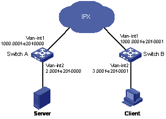
Figure 3-1 IPX network diagram
III. Configuration procedure
1) Configure Switch A.
# Enable IPX.
<H3C> system-view
[H3C] ipx enable
# Assign the network number 2 to VLAN interface 2 and enable IPX on the VLAN interface.
[H3C] interface Vlan-interface 2
[H3C-Vlan-interface2] ipx network 2
# Set the packet encapsulation format to Ethernet_II on VLAN interface 2.
[H3C-Vlan-interface2] ipx encapsulation ethernet-2
[H3C-Vlan-interface2] quit
# Assign the network number 1000 to VLAN interface 1 and enable IPX on the VLAN interface.
[H3C] interface Vlan-interface 1
[H3C-Vlan-interface1] ipx network 1000
# Configure a static route with the destination network number 3.
[H3C-Vlan-interface1] quit
[H3C] ipx route-static 3 1000.000f-e20f-0001 tick 7 hop 2
2) Configure Switch B.
# Enable IPX.
[H3C] ipx enable
# Assign the network number 3 to VLAN interface 2 and enable IPX on the VLAN interface.
[H3C] interface Vlan-interface 2
[H3C-Vlan-interface2] ipx network 3
# Set the packet encapsulation format to Ethernet_SNAP on VLAN interface 2.
[H3C-Vlan-interface2] ipx encapsulation snap
[H3C-Vlan-interface2] quit
# Assign the network number 1000 to VLAN interface 1 and enable IPX on the VLAN interface.
[H3C] interface Vlan-interface 1
[H3C-Vlan-interface1] ipx network 1000
# Configure a static route with the destination network number 2.
[H3C-Vlan-interface1] quit
[H3C] ipx route-static 2 1000.000f-e20f-0000 tick 7 hop 2
# Configure a service information entry, indicating that Server can provide the file service.
[H3C] ipx service 4 fileserver 2.0000-0c91-f61f 451 hop 2
# Configure a service information entry, indicating that the server can provide the printing service.
[H3C] ipx service 7 printserver 2.0000-0c91-f61f 5 hop 2
3.5 Troubleshooting IPX Configuration
I. Troubleshooting IPX forwarding
Symptom 1: A destination address cannot be pinged through.
Solutions:
l Check whether the destination address is correct.
l Use the display ipx interface command to check whether the network number and IPX frame encapsulation format configured on the interface of the switch are consistent with those configured on the connected interface.
l Use the display ipx routing-table command to check whether the destination network is reachable.
l Use the debugging ipx packet command to enable debugging for IPX packets. Check whether IPX packets are correctly received, transmitted, forwarded, and dropped.
Symptom 2: Packets are dropped.
Solutions:
l If the IPX packet debugging information shows that a packet is dropped because ”Packet size is greater than interface MTU!”, perform the following operations: View the MTU setting on the VLAN interface using the display interface command and the RIP/SAP packet size using the display ipx interface command. Check whether the RIP/SAP packet size is smaller than the MTU setting on the VLAN interface.
Symptom 3: The switch cannot receive SAP packets.
Solutions:
l Use the display ipx interface command to check whether SAP is disabled on the VLAN interface.
Symptom 4: An IPX packet of Type 20 cannot be transmitted to other network segments.
Solutions:
l Use the display ipx interface command to check whether the forwarding of type 20 IPX packets is enabled on the input and output interfaces.
l Use the debugging ipx packet command to enable debugging for IPX packets. Check whether there is a prompt message of ”Transport Control field of IPX type-20 packet >= 8!” A Type 20 IPX packet can only be forwarded up to eight times; for the ninth forwarding attempt, the packet is dropped.
II. Troubleshooting IPX RIP
Symptom 1: The switch cannot learn routes from the peer device.
Solutions:
l Use the debugging ipx rip packet verbose command to enable debugging for IPX RIP. Check whether there is an RIP packet with routing information from the peer device to make sure that the underlying connection is available between the two devices.
l If there is an RIP packet with routing information from the peer device, you can use the debugging ipx rip event command to check whether the received routing information is added into the routing table.
Symptom 2: Try to import a static route to IPX RIP, but the static route is not sent out.
Solutions:
l Use the display ipx routing-table command to check whether the static route exists.
l If the static route is not in the routing table, use the display ipx routing-table verbose command to check whether it exists as an inactive route. If the static route exists, check the reason. When the route becomes active, it can be advertised as an RIP route.
l If the configured static route is shown in the routing table, check whether its hop count is smaller than 15. If the hop count is larger than or equal to 15, it is normal that the static route is not advertised successfully.
III. Troubleshooting IPX SAP
Symptom 1: Unable to add static service information into the service information table.
Solutions:
l Use the display ipx service-table inactive command to check whether the service information is in the inactive service information table. If yes, there is no active route to the server.
l Check whether the number of service information entries exceeds the limitation using the display ipx service-table command. IPX can support 10,240 service information entries with up to 5,120 service types and 5,120 static service information entries.
Symptom 2: A service information entry cannot be found in the service information table.
Solutions:
l Use the display ipx service-table inactive command to check whether the service information is in the inactive service information table. If yes, there is no active route to the server.
l Check whether the VLAN interface is UP and SAP is enabled using the display ipx interface command.
l Check whether the hop count of the route to the server is smaller than 16 using the display ipx routing-table command.
l Check whether adequate memory is available for adding the service entry into the service information table. You can try to add it as a static service entry.
Symptom 3: No new dynamic service entry is found in the service information table.
Solutions:
l Check whether the relevant packets are received using the debugging ipx packet and debugging ipx sap packet verbose commands. If the packets are not received, the underlying network connection is abnormal.
l Check whether IPX is disabled. If yes, enable IPX using the ipx enable command.
l Check whether IPX is configured on the VLAN interface using the display ipx interface command.
l Check whether SAP is disabled. If yes, enable SAP using the undo ipx sap disable command.
l Use the display ipx service-table command to check whether the number of SAP service entries is under the limit. IPX can support 10,240 service entries with 5,120 service types.
l Check whether the MTU of SAP packets is less than or equal to the MTU at the physical layer.
Symptom 4: No update packet is received on the VLAN interface.
Solutions:
l Check whether there are update packets using the debugging ipx packet and debugging ipx sap packet verbose commands. All the received/transmitted packets can be displayed through debugging information. If there are no update packets, it indicates that the underlying network connection is abnormal.
l Use the display ipx interface command to check whether SAP is enabled.
l Check whether the hop count of the active route to the server is smaller than 16.
l Use the display current-configuration command to check whether the update interval is too long.
l Use the display current-configuration command to check whether the triggered updates feature is configured on the VLAN interface. Periodical update is disabled when the triggered updates feature applies.
Symptom 5: No update packets are sent out of the VLAN interface.
Solutions:
l Check whether there are update packets using the debugging ipx packet and debugging ipx sap packet verbose commands. Check whether the MTU of the SAP packets is smaller than the MTU of the VLAN interface to guarantee that they are not dropped by the underlying layer.
l Use the display current-configuration command to check whether the triggered-update feature is configured on the VLAN interface. Periodical update is disabled when the triggered-updates feature applies.
l Check whether all service information is learnt from the VLAN interface. Then check whether split-horizon is enabled on the VLAN interface.
Symptom 6: SAP does not respond to GNS requests.
Solutions:
l Use the debugging ipx packet sap command to check whether the switch receives the GNS packets.
l Check whether SAP is enabled on the VLAN interface.
l Use the display ipx interface command to check whether the VLAN interface is enabled to respond to GNS requests. If GNS reply is disabled, use the undo ipx sap gns-disable-reply command to enable the interface to respond to the GNS requests.
l Use the display ipx service table command to check whether the requested service information is available in the service information table.
l If the requested service information is available in the service information table, but SAP still does not give response, you need to check whether the service information is learnt from the interface where the request is received.
Symptom 7: SAP does not respond to a GNS request through Round-Robin.
Solutions:
l Use the display current-configuration command to check whether Round-Robin is enabled.
l If Round-Robin is enabled, check whether multiple equivalent service entries are available for the service request. The service entries are considered equivalent only when they have the same RIP delay, RIP hop count, SAP hop count and SAP preference.
IV. Troubleshooting IPX routing management
Symptom 1: The current switch receives the routing information from a neighbor device, but the route cannot be found on the current switch using the display ipx routing-table verbose command.
Solutions:
l Use the display current-configuration command to view the maximum number of dynamic routes for each destination network number. The corresponding command is ipx route max-reserve-path. The default value is 4.
l Use the display ipx routing-table verbose command to check whether the number of the existing dynamic routes to the destination network is under the limit.
l If the number of dynamic route entries with the destination network number reaches the limit, use the ipx route max-reserve-path command to set a higher limit to accommodate new dynamic route information.