- Table of Contents
-
- H3C S7500 Series Operation Manual(Release 3100 Series)-(V1.04)
- 00-1Cover
- 00-2Overview
- 01-CLI Configuration
- 02-Login Configuration
- 03-Configuration File Management Configuration
- 04-VLAN Configuration
- 05-Extended VLAN Application Configuration
- 06-IP Address-IP Performance-IPX Configuration
- 07-GVRP Configuration
- 08-QinQ Configuration
- 09-Port Basic Configuration
- 10-Link Aggregation Configuration
- 11-Port Isolation Configuration
- 12-Port Binding Configuration
- 13-DLDP Configuration
- 14-MAC Address Table Configuration
- 15-MSTP Configuration
- 16-Routing Protocol Configuration
- 17-Multicast Configuration
- 18-802.1x Configuration
- 19-AAA-RADIUS-HWTACACS-EAD Configuration
- 20-Traffic Accounting Configuration
- 21-VRRP-HA Configuration
- 22-ARP Configuration
- 23-DHCP Configuration
- 24-ACL Configuration
- 25-QoS Configuration
- 26-Mirroring Configuration
- 27-Cluster Configuration
- 28-PoE Configuration
- 29-UDP-Helper Configuration
- 30-SNMP-RMON Configuration
- 31-NTP Configuration
- 32-SSH Terminal Service Configuration
- 33-File System Management Configuration
- 34-FTP and TFTP Configuration
- 35-Information Center Configuration
- 36-DNS Configuration
- 37-System Maintenance and Debugging Configuration
- 38-HWPing Configuration
- 39-RRPP Configuration
- 40-NAT-Netstream-Policy Routing Configuration
- 41-Telnet Protection Configuration
- 42-Hardware-Dependent Software Configuration
- Related Documents
-
| Title | Size | Download |
|---|---|---|
| 24-ACL Configuration | 264 KB |
Table of Contents
1.1.2 Ways to Apply ACL on a Switch
1.1.3 ACLs Based on Time Ranges
1.1.4 Types of ACLs Supported by Ethernet Switches
1.2 Choosing ACL Mode for Traffic Flows
1.3 Specifying the Match Order of ACL Rules
1.5.1 Configuration Prerequisites
1.6.1 Configuration Prerequisites
1.7.1 Configuration Prerequisites
1.8 Defining User-Defined ACLs
1.8.1 Configuration Prerequisites
1.9.1 Configuration Preparation
1.10 Displaying ACL Configuration
1.11 ACL Configuration Examples
1.11.1 Basic ACL Configuration Example
1.11.2 Advanced ACL Configuration Example
1.11.3 Layer 2 ACL Configuration Example
1.11.4 User-Defined ACL Configuration Example
Chapter 1 ACL Configuration
& Note:
Type A line processing units (LPUs) include LS81FT48A, LS81FM24A, LS81FS24A, LS81GB8UA, LS81GT8UA, LS81FT48, LS81FM24, LS81FS24, LS81GB8U and LS81GT8U.
When configuring ACL, go to these sections for information you are interested in:
l Choosing ACL Mode for Traffic Flows
l Specifying the Match Order of ACL Rules
l Displaying ACL Configuration
1.1 ACL Overview
An access control list (ACL) is used primarily to identify traffic flows. In order to filter data packets, a series of match rules must be configured on the network device to identify the packets to be filtered. After the specific packets are identified, and based on the predefined policy, the network device can permit/prohibit the corresponding packets to pass.
ACLs classify packets based on a series of match conditions, which can be the source addresses, destination addresses and port numbers carried in the packets.
The packet match rules defined by ACLs can be referenced by other functions that need to differentiate traffic flows, such as the definition of traffic classification rules in QoS.
According to the application purpose, ACLs fall into the following four types:
l Basic ACL: rules are made based on the Layer 3 source IP addresses only.
l Advanced ACL: rules are made based on the Layer 3 and Layer 4 information such as the source and destination IP addresses of the data packets, the type of protocol over IP, protocol-specific features, and so on.
l Layer 2 ACL: rules are made based on the Layer 2 information such as the source and destination MAC address, VLAN priority, Layer 2 protocol, and so on.
l User-defined ACL: such rules specify a byte in the packet, by its offset from the packet header, as the starting point to perform logical AND operations, and compare the extracted string with the user-defined string to find the matching packets for processing.
1.1.1 ACL Match Order
An ACL may contain a number of rules, which specify different packet ranges. This brings about the issue of match order when these rules are used to filter packets.
An ACL supports the following two types of match orders:
l Configured order: ACL rules are matched according to the configured order.
l Automatic ordering: ACL rules are matched according to the “depth-first” order.
I. IP ACL depth-first order
With the depth-first rule adopted, the rules of an IP ACL (basic and advanced) are matched in the following order:
1) Protocol range of ACL rules. The range of IP protocol is 1 to 255 and those of other protocols over IP are the same as the corresponding protocol numbers. The smaller the protocol range, the higher the priority.
2) Range of source IP address. The smaller the source IP address range (that is, the longer the mask), the higher the priority.
3) Range of destination IP address. The smaller the destination IP address range (that is, the longer the mask), the higher the priority.
4) Range of Layer 4 port number, that is, of TCP/UDP port number. The smaller the range, the higher the priority.
If rule A and rule B are the same in all the four ACEs (access control elements) above, and also in their numbers of other ACEs to be considered in deciding their priority order, weighting principles will be used in deciding their priority order.
The weighting principles work as follows:
l Each ACE is given a fixed weighting value. This weighting value and the value of the ACE itself will jointly decide the final matching order. The weighting values of ACEs rank in the following descending order: DSCP, ToS, ICMP, established, precedence, fragment.
l The weighting value of each ACE of the rule is deducted from a fixed weighting value. The smaller the weighting value left, the higher the priority.
l If the number and type of ACEs are the same for multiple rules, then the sum of ACE values of a rule determines its priority. The smaller the sum, the higher the priority.
II. Layer 2 ACL depth-first order
With the depth-first order adopted, the rules of a Layer 2 ACL are matched in the order of the mask length of the source MAC address and destination MAC address, the longer the mask, the higher the match priority. If two mask lengths are the same, the priority of the match rule configured earlier is higher. For example, the priority of the rule with source MAC address mask FFFF-FFFF-0000 is higher than that of the rule with source MAC address mask FFFF-0000-0000.
1.1.2 Ways to Apply ACL on a Switch
I. ACLs activated directly on the hardware
In a switch, an ACL can be directly activated on the switch hardware for packet filtering and traffic classification in the data forwarding process. You can use the acl order command to specify the match order for the rules in the ACL. For detailed configuration, refer to Specifying the Match Order of ACL Rules.
ACLs are directly activated on the switch hardware in the following situations: the switch references ACLs to implement the QoS functions, and forwards data through ACLs.
II. ACL referenced by the upper-level modules
The switch also uses ACLs to filter packets processed by software and implements traffic classification. In this case, there are two types of match orders for the rules in an ACL: config (user-defined match order) and auto (the system performs automatic ordering, namely according to the “depth-first” order). In this scenario, you can specify the match order for multiple rules in an ACL. You cannot modify the match order for an ACL once you have specified it. You can specify anew the match order only after all the rules are deleted from the ACL.
ACLs can also be referenced by route policies or be used to control login users.
1.1.3 ACLs Based on Time Ranges
A time range-based ACL enables you to implement ACL control over packets by differentiating the time ranges.
A time range can be specified in each rule in an ACL. If the time range specified in a rule is not configured, the system will give a prompt message and allow such a rule to be successfully created. However, the rule does not take effect immediately. It takes effect only when the specified time range is configured and the system time is within the time range. If you remove the time range of an ACL rule, the ACL rule becomes invalid the next time the ACL rule timer refreshes.
1.1.4 Types of ACLs Supported by Ethernet Switches
The following types of ACLs are supported by Ethernet switches:
l User-defined ACL
1.2 Choosing ACL Mode for Traffic Flows
A switch can only choose one ACL mode for traffic flows, Layer 2 ACL mode or Layer 3 ACL mode. In Layer 2 ACL mode, only Layer 2 ACL can be activated or imported by other applications, and Layer 3 ACL mode is similar.
1.2.1 Configuration Procedure
Table 1-1 Choose ACL mode for traffic flows
|
To do… |
Use the command... |
Remarks |
|
Enter system view |
system-view |
— |
|
Choose ACL mode for traffic flows |
acl mode { ip-based | link-based } |
Required By default, a switch chooses ip-based ACL mode for traffic flows, that is, ACL classifies the traffic flows based on Layer 3 information. |
|
Display the ACL mode for traffic flows |
display acl mode |
Optional The display command can be executed in any view |
& Note:
This configuration is only effective on Type A line processing units (LPUs).
1.2.2 Configuration Example
# Configure the ACL mode for traffic flows as link-based.
<H3C> system-view
[H3C] acl mode link-based
[H3C] display acl mode
The current acl mode: link-based.
1.3 Specifying the Match Order of ACL Rules
The acl match-order { config | auto } command is used to set the matching order of ACL rules when they are configured. The acl order command is used to set the matching order of ACL rules in the case that they are applied to a port. The S7500 Switches support three matching orders of ACL rules applied to a port: depth-first, first-config-first-match, and last-config-first match. You can specify one of the three orders.
1.3.1 Configuration Procedure
Table 1-2 Set the matching order of ACL rules sent to a port
|
To do... |
Use the command... |
Remarks |
|
Enter system view |
system-view |
— |
|
Set the matching order of the configured ACL rules sent to a port |
acl order { auto | first-config-first-match | last-config-first-match } |
Required By default, the configured ACL rules sent to a port match in the depth-first order, that is, the auto mode. |
|
Display the traffic flows ACL mode |
display acl order |
Optional The display command can be executed in any view |
1.3.2 Configuration Example
# Specify the matching order of ACL rules applied to a port as first-config-first-match.
<H3C> system-view
[H3C] acl order first-config-first-match
[H3C] display acl order
the current order is first-config-first-match
1.4 Configuring Time Ranges
The time range configuration tasks include configuring periodic time ranges and configuring absolute time ranges. A periodic time range recurs periodically on the day or days of the week, while an absolute time range takes effect only in a period of time (the start time to the end time) and does not recur.
& Note:
An absolute time range on an H3C S5600 switch can be within the range 1970/1/1 00:00 to 2100/12/31 23:59.
1.4.1 Configuration Procedure
Table 1-3 Configure a time range
|
To do... |
Use the command... |
Remarks |
|
Enter system view |
system-view |
— |
|
Create a time range |
time-range time-name { start-time to end-time days-of-the-week [ from start-time start-date ] [ to end-time end-date ] | from start-time start-date [ to end-time end-date ] | to end-time end-date } |
Required |
|
Display a specified time range or all time ranges |
display time-range { all | time-name } |
Optional This command can be executed in any view. |
Note that:
If only a periodic time section is defined in a time range, the time range is active only when the system time within the defined periodic time section. If multiple periodic time sections are defined in a time range, the time range is active only when the system time is within one of the periodic time sections.
If only an absolute time section is defined in a time range, the time range is active only when the system time within the defined absolute time section. If multiple absolute time sections are defined in a time range, the time range is active only when the system time is within one of the absolute time sections.
If both a periodic time section and an absolute time section are defined in a time range, the time range is active only when the periodic time range and the absolute time range are both matched. Assume that a time range contains an absolute time section ranging from 00:00 January 1, 2004 to 23:59 December 31, 2004, and a periodic time section ranging from 12:00 to 14:00 on every Wednesday. This time range is active only when the system time within the range from 12:00 to 14:00 on every Wednesday in 2004.
If the start time is not specified, the time section starts on the earliest date available in the system and ends on the specified end date. If the end date is not specified, the time section starts from the specified start date to 2100/12/31 23:59.
1.4.2 Configuration Example
# Define a periodic time range that will be active from 8:00 to 18:00 on Monday through Friday.
<H3C> system-view
[H3C] time-range test 8:00 to 18:00 working-day
[H3C] display time-range test
Current time is 13:27:32 4/16/2005 Saturday
Time-range : test ( Inactive )
08:00 to 18:00 working-day
# Define an absolute time range from 15:00 1/28/2000 to 15:00 1/28/2004.
<H3C> system-view
[H3C] time-range test from 15:00 1/28/2000 to 15:00 1/28/2004
[H3C] display time-range test
Current time is 13:30:32 4/16/2005 Saturday
Time-range : test ( Inactive )
From 15:00 Jan/28/2000 to 15:00 Jan/28/2004
1.5 Defining Basic ACLs
The value range for basic ACL numbers is 2,000 to 2,999.
1.5.1 Configuration Prerequisites
Before configuring an ACL rule containing time range arguments, you need to define the corresponding time ranges. For the configuration of time ranges, refer to Configuring Time Ranges
The value of the source IP address information in the rule has been defined.
1.5.2 Configuration Procedure
Table 1-4 Define a basic ACL rule
|
To do... |
Use the command... |
Remarks |
|
Enter system view |
system-view |
— |
|
Create or enter basic ACL view |
acl { number acl-number | name acl-name [ advanced | basic | link | user ] } [ match-order { config | auto } ] |
Required By the default, the match order is config. |
|
Define an rule |
rule [ rule-id ] { permit | deny } [ source { source-addr wildcard | any } | fragment | time-range time-name ]* |
Required |
|
Display ACL information |
display acl config { all | acl-number | acl-name } |
Optional This command can be executed in any view. |
In the case that you specify the rule ID when defining a rule:
l If the ACL is created with the config keyword specified and the rule identified by the rule-id argument exists, the settings specified in the rule command overwrite the counterparts of the existing rule (other settings of the rule remain unchanged). If the ACL is created with the auto keyword specified, the rules of the ACL cannot be edited. In this case, the system prompts errors when you execute the rule command.
l If the rule corresponding to the specified rule ID does not exist, you will create and define a new rule.
If you do not specify a rule ID, you will create and define a new rule, and the system will assign an ID for the rule automatically.
1.5.3 Configuration Example
# Configure ACL 2000 to deny packets with source IP address being 1.1.1.1.
<H3C> system-view
[H3C] acl number 2000
[H3C-acl-basic-2000] rule deny source 1.1.1.1 0
[H3C-acl-basic-2000] display acl config 2000
Basic ACL 2000, 1 rule
rule 0 deny source 1.1.1.1 0 (0 times matched)
1.6 Defining Advanced ACLs
Advanced ACLs define classification rules according to the source and destination IP addresses of packets, the type of protocol over IP, and protocol-specific features such as TCP/UDP source and destination ports, ICMP protocol type, code, and so on.
The value range for advanced ACL numbers is 3,000 to 3,999. Note that ACL 3998 and ACL 3999 cannot be configured because they are reserved for the cluster management.
Using advanced ACLs, you can define classification rules that are more accurate, abundant, and flexible than those defined with basic ACLs.
1.6.1 Configuration Prerequisites
Before configuring an ACL rule containing time range arguments, you need to define the corresponding time ranges. For the configuration of time ranges, refer to Configuring Time Ranges.
The values of source and destination IP addresses, the type of the protocols over IP, and protocol-specific features in the rule have been defined.
1.6.2 Configuration Procedure
Table 1-5 Define an advanced ACL rule
|
To do... |
Use the command... |
Remarks |
|
Enter system view |
system-view |
— |
|
Create or enter advanced ACL view |
acl { number acl-number | name acl-name [ advanced | basic | link | user ] } [ match-order { config | auto } ] |
Required By the default, the match order is config. |
|
Define an rule |
rule [ rule-id ] { permit | deny } rule-string |
Required |
|
Display ACL information |
display acl config { all | acl-number | acl-name } |
Optional This command can be executed in any view. |
rule-string: rule information, which can be combination of the parameters described in Table 1-6. You must configure the protocol argument in the rule information before you can configure other arguments.
|
Parameter |
Type |
Function |
Remarks |
|
protocol |
Protocol type |
Type of protocol over IP |
When expressed in numerals, the value range is 1 to 255. When expressed with a name, the value can be GRE, ICMP, IGMP, IP, IPinIP, OSPF, TCP, and UDP. |
|
source { sour-addr sour-wildcard | any } |
Source address information |
Specifies the source address information in the rule |
sour-addr sour-wildcard is used to specify the source address of the packet, expressed in dotted decimal notation. any represents all source addresses. |
|
destination { dest-addr dest-wildcard | any } |
Destination address information |
Specifies the destination address information in the rule |
dest-addr dest-wildcard is used to specify the destination address of the packet, expressed in dotted decimal notation. any represents all destination address. |
|
precedence precedence |
Packet precedence |
IP priority |
Value range: 0 to 7 |
|
tos tos |
Packet precedence |
ToS priority |
Value range: 0 to 15 |
|
dscp dscp |
Packet precedence |
DSCP priority |
Value range: 0 to 63 |
|
fragment |
Fragment information |
Specifies that the ACL rule is effective for non-initial fragment packets |
— |
|
time-range time-name |
Time range information |
Specifies the time range in which the ACL rule is active |
— |
& Note:
sour-wildcard and dest-wildcard represent the wildcard masks of the destination subnet masks, provided in dotted decimal notation. For example, if you want to specify the subnet mask as 255.255.0.0, you need to input 0.0.255.255. The wildcard mask can be 0, representing the host address.
To define DSCP priority, you can directly input a value ranging from 0 to 63, or input a keyword listed in Table 1-7.
Table 1-7 Description of DSCP values
|
Keyword |
DSCP value in decimal |
DSCP value in binary |
|
ef |
46 |
101110 |
|
af11 |
10 |
001010 |
|
af12 |
12 |
001100 |
|
af13 |
14 |
001110 |
|
af21 |
18 |
010010 |
|
af22 |
20 |
010100 |
|
af23 |
22 |
010110 |
|
af31 |
26 |
011010 |
|
af32 |
28 |
011100 |
|
af33 |
30 |
011110 |
|
af41 |
34 |
100010 |
|
af42 |
36 |
100100 |
|
af43 |
38 |
100110 |
|
cs1 |
8 |
001000 |
|
cs2 |
16 |
010000 |
|
cs3 |
24 |
011000 |
|
cs4 |
32 |
100000 |
|
cs5 |
40 |
101000 |
|
cs6 |
48 |
110000 |
|
cs7 |
56 |
111000 |
|
be (default) |
0 |
000000 |
To define the IP precedence, you can directly input a value ranging from 0 to 7, or input a keyword listed in the following table.
Table 1-8 Description of IP precedence value
|
Keyword |
IP Precedence value in decimal |
IP Precedence value in binary |
|
routine |
0 |
000 |
|
priority |
1 |
001 |
|
immediate |
2 |
010 |
|
flash |
3 |
011 |
|
flash-override |
4 |
100 |
|
critical |
5 |
101 |
|
internet |
6 |
110 |
|
network |
7 |
111 |
Table 1-9 Description of ToS value
|
Keyword |
ToS value in decimal |
ToS value in binary |
|
normal |
0 |
0000 |
|
min-monetary-cost |
1 |
0001 |
|
max-reliability |
2 |
0010 |
|
max-throughput |
4 |
0100 |
|
min-delay |
8 |
1000 |
If the protocol type is TCP or UDP, you can also define the following information:
Table 1-10 TCP/UDP-specific rule information
|
Parameter |
Type |
Function |
Remarks |
|
source-port operator port1 [ port2 ] |
Source port(s) |
Defines the source port information of UDP/TCP packets |
The value of operator can be lt (less than), gt (greater than), eq (equal to), neq (not equal to) or range (within the range of). Only the “range” operator requires two port numbers as the operands, and other operators require only one port number as the operand. port1, port2: TCP/UDP port number(s), expressed with name(s) or numerals; when expressed with numerals, the value range is 0 to 65,535 |
|
destination-port operator port1 [ port2 ] |
Destination port(s) |
Defines the destination port information of UDP/TCP packets |
|
|
established |
“TCP connection established” flag |
Specifies that the rule is applicable only to the first SYN segment for establishing a TCP connection |
TCP-specific argument |
& Note:
If the protocol type is ICMP, you can also define the following information:
Table 1-11 ICMP-specific rule information
|
Parameter |
Type |
Function |
Remarks |
|
icmp-type icmp-type icmp-code |
Type and message code information of ICMP packets |
Specifies the type and message code information of ICMP packets in the ACL rule |
icmp-type: ICMP message type, ranging 0 to 255 icmp-code: ICMP message code, ranging 0 to 255 |
|
Name |
ICMP TYPE |
ICMP CODE |
|
echo |
Type=8 |
Code=0 |
|
echo-reply |
Type=0 |
Code=0 |
|
fragmentneed-DFset |
Type=3 |
Code=4 |
|
host-redirect |
Type=5 |
Code=1 |
|
host-tos-redirect |
Type=5 |
Code=3 |
|
host-unreachable |
Type=3 |
Code=1 |
|
information-reply |
Type=16 |
Code=0 |
|
information-request |
Type=15 |
Code=0 |
|
net-redirect |
Type=5 |
Code=0 |
|
net-tos-redirect |
Type=5 |
Code=2 |
|
net-unreachable |
Type=3 |
Code=0 |
|
parameter-problem |
Type=12 |
Code=0 |
|
port-unreachable |
Type=3 |
Code=3 |
|
protocol-unreachable |
Type=3 |
Code=2 |
|
reassembly-timeout |
Type=11 |
Code=1 |
|
source-quench |
Type=4 |
Code=0 |
|
source-route-failed |
Type=3 |
Code=5 |
|
timestamp-reply |
Type=14 |
Code=0 |
|
timestamp-request |
Type=13 |
Code=0 |
|
ttl-exceeded |
Type=11 |
Code=0 |
In the case that you specify the rule ID when defining a rule:
l If the ACL is created with the config keyword specified and the rule identified by the rule-id argument exists, the settings specified in the rule command overwrite the counterparts of the existing rule (other settings of the rule remain unchanged). If the ACL is created the auto keyword specified, the rules of the ACL cannot be edited. In this case, the system will prompt errors when you execute the rule command.
l If the rule corresponding to the specified rule ID does not exist, you will create and define a new rule.
l The content of a modified or newly created rule must not be identical with the content of any existing rule; otherwise the rule modification or creation will be failed, and the system will prompt that the rule already exists.
If you do not specify a rule ID, you will create and define a new rule, and the system will assign an ID for the rule automatically.
1.6.3 Configuration Example
# Configure ACL 3000 to permit TCP packets to pass. The port number of the packets is 80, the source network segment of packets is 129.9.0.0, and the destination network segment is 202.38.160.0
<H3C> system-view
[H3C] acl number 3000
[H3C-acl-adv-3000] rule permit tcp source 129.9.0.0 0.0.255.255 destination 202.38.160.0 0.0.0.255 destination-port eq 80
[H3C-acl-adv-3000] display acl config 3000
Advanced ACL 3000, 1 rule
rule 0 permit tcp source 129.9.0.0 0.0.255.255 destination 202.38.160.0 0.0.0.255 destination-port eq www (0 times matched)
1.7 Defining Layer 2 ACLs
The value range for Layer 2 ACL numbers is 4,000 to 4,999.
1.7.1 Configuration Prerequisites
Before configuring an ACL rule containing time range arguments, you need to define the corresponding time ranges. For the configuration of time ranges, refer to Configuring Time Ranges.
1.7.2 Configuration Procedure
Table 1-13 Create a Layer 2 ACL rule
|
To do... |
Use the command... |
Remarks |
|
Enter system view |
system-view |
— |
|
Create or enter layer 2 ACL view |
acl { number acl-number | name acl-name [ advanced | basic | link | user ] } [ match-order { config | auto } ] |
Required By default, the match order is config. |
|
Define an ACL rule |
rule [ rule-id ] { permit | deny } [ rule-string ] |
Required If you do not specify the rule-string argument, the switch will choose ingress any egress any by default. |
|
Display ACL information |
display acl config { all | acl-number | acl-name } |
Optional This command can be executed in any view. |
rule-string: rule information, which can be combination of the parameters described in Table 1-14.
|
Parameter |
Type |
Function |
Remarks |
|
protocol-type |
Protocol type |
Defines the protocol type over Ethernet frames |
protocol-type: the value can be ip, arp, rarp, ipx, nbx, pppoe-control, or pppoe-data. When the protocol type is arp, the rules cannot match the ARP packets with the destination MAC address as the MAC address of Layer 3 interface or with the destination MAC address being all Fs. |
|
format-type |
Link layer encapsulation type |
Defines the link layer encapsulation type in the rule |
format-type: the value can be 802.3/802.2, 802.3, ether_ii, or snap. |
|
ingress { { source-vlan-id | source-mac-addr [ source-mac-mask ] }* | any } |
Source MAC address information |
Specifies the source MAC address range in the ACL rule |
source-mac-addr: source MAC address, in the format of H-H-H source-mac-mask: source MAC address mask, in the format of H-H-H, defaults to ffff-ffff-ffff. source-vlan-id: source VLAN ID, in the range of 1 to 4,094 any represents all packets received from all ports. |
|
egress { dest-mac-addr [ dest-mac-mask ] | any } |
Destination MAC address information |
Specifies the destination MAC address range in the ACL rule |
dest-mac-addr: destination MAC address, in the format of H-H-H dest-mac-mask: destination MAC address mask, in the format of H-H-H, defaults to ffff-ffff-ffff. any represents all packets forwarded by all ports. |
|
cos cos |
Priority |
Defines the 802.1p priority of the ACL rule |
cos: ranges from 0 to 7 |
|
time-range time-name |
Time range information |
Specifies the time range in which the rule is active |
time-name: name of a time range in which the ACL rule is active; a string of 1 to 32 characters |
& Note:
source-mac-mask and dest-mac-mask represent the MAC address masks. For example, if you want to specify a MAC address range from 0011-0011-0000 to 0011-0011-00ff, you can specify ffff-ffff-ff00 as the MAC address mask. The mask can be all Fs, representing the host address.
Table 1-15 Description of CoS value
|
Keyword |
CoS value in decimal |
CoS value in binary |
|
best-effort |
0 |
000 |
|
background |
1 |
001 |
|
spare |
2 |
010 |
|
excellent-effort |
3 |
011 |
|
controlled-load |
4 |
100 |
|
video |
5 |
101 |
|
voice |
6 |
110 |
|
network-management |
7 |
111 |
In the case that you specify the rule ID when defining a rule:
l If the ACL is created with the config keyword specified and the rule identified by the rule-id argument exists, the settings specified in the rule command overwrite the counterparts of the existing rule (other settings of the rule remain unchanged). If the ACL is created the auto keyword specified, the rules of the ACL cannot be edited. In this case, the system will prompt errors when you execute the rule command.
l If the rule corresponding to the specified rule ID does not exist, you will create and define a new rule.
l The content of a modified or newly created rule must not be identical with the content of any existing rule; otherwise the rule modification or creation will be failed, and the system will prompt that the rule already exists.
1.7.3 Configuration Example
# Configure ACL 4000 to deny packets whose 802.1p priority is 3, source MAC address is 000d-88f5-97ed, and destination MAC address is 011-4301-991e.
<H3C> system-view
[H3C] acl number 4000
[H3C-acl-ethernetframe-4000] rule deny cos 3 source 000d-88f5-97ed ffff-ffff-ffff dest 0011-4301-991e ffff-ffff-ffff
[H3C-acl-ethernetframe-4000] display acl config 4000
Ethernet frame ACL 4000, 1 rule
rule 0 deny cos excellent-effort source 000d-88f5-97ed ffff-ffff-ffff dest 0011-4301-991e ffff-ffff-ffff (0 times matched)
1.8 Defining User-Defined ACLs
Using a byte, which is specified through its offset from the packet header, in the packet as the starting point, user-defined ACLs perform logical AND operations on packets and compare the extracted string with the user-defined string to find the matching packets for processing.
User-defined ACL numbers range from 5,000 to 5,999.
1.8.1 Configuration Prerequisites
To configure a time range-based ACL rule, you need first to define the corresponding time range, as described in Configuring Time Ranges.
1.8.2 Configuration Procedure
Table 1-16 Define a user-defined ACL rule
|
To do... |
Use the command... |
Remarks |
|
Enter system view |
system-view |
— |
|
Create or enter user-defined ACL view |
acl { number acl-number | name acl-name [ advanced | basic | link | user ] } [ match-order { config | auto } ] |
Required By default, the match order is config. |
|
Define an ACL rule |
rule [ rule-id ] { permit | deny } { rule-string rule-mask offset } &<1-8> [ time-range time-name ] |
Required |
|
Display ACL information |
display acl config { all | acl-number | acl-name } |
Optional This command can be executed in any view. |
When you specify the rule ID by using the rule command, note that:
l If the ACL is created with the config keyword specified and the rule identified by the rule-id argument exists, the settings specified in the rule command overwrite the counterparts of the existing rule (other settings of the rule remain unchanged). If the ACL is created the auto keyword specified, the rules of the ACL cannot be edited. In this case, the system will prompt errors when you execute the rule command.
l If the rule corresponding to the specified rule ID does not exist, you will create and define a new rule.
l The content of a modified or newly created rule must not be identical with the content of any existing rule; otherwise the rule modification or creation will be failed, and the system will prompt that the rule already exists.
If you do not specify a rule ID, you will create and define a new rule, and the system will assign an ID for the rule automatically.
& Note:
Only LPUs other than Type A support the user-defined ACL.
1.8.3 Configuration Example
# Configure ACL 5001 to deny all TCP packets.
<H3C> system-view
[H3C] time-range t1 18:00 to 23:00 sat
[H3C] acl number 5001
[H3C-acl-user-5001] rule 25 deny 06 ff 27 time-range t1
[H3C-acl-user-5001] display acl config 5001
User defined ACL 5001, 1 rule
rule 25 deny 06 ff 27 time-range t1 (0 times matched) (Inactive)
1.9 Applying ACLs on Ports
By applying ACLs on ports, you can filter certain packets.
1.9.1 Configuration Preparation
You need to define an ACL before applying it on a port. For operations to define ACLs, refer to Defining Basic ACLs, Defining Advanced ACLs, Defining Layer 2 ACLs, and Defining User-Defined ACLs.
1.9.2 Configuration Procedure
Table 1-17 Apply an ACL on a port
|
To do... |
Use the command... |
Remarks |
|
Enter system view |
system-view |
— |
|
Enter Ethernet port view |
interface interface-type interface-number |
— |
|
Enter QoS view |
qos |
— |
|
Apply an ACL on the port |
packet-filter { inbound | outbound } acl-rule [ system-index ] [ not-care-for-interface ] |
Required This command is supported by Type A LPUs. |
|
packet-filter inbound acl-rule [ system-index ] |
Required This command is supported by LPUs other than Type A. |
|
|
Display information about ACLs applied to a port or all ports. |
display acl running-packet-filter { all | interface interface-type interface-number } |
Optional This command can be executed in any view. |
acl-rule: Applied ACL, which can be a combination of different types of ACL rules. Table 1-18 and Table 1-20 describe the ACL combinations on Type A LPUs and the corresponding parameter description. Table 1-19 and Table 1-20 describe the ACL combinations on LPUs other than Type A and the corresponding parameter description.
Table 1-18 Combined application of ACLs on service Type A LPUs
|
Combination mode |
Form of acl-rule |
|
Apply all rules in an IP type ACL |
ip-group { acl-number | acl-name } |
|
Apply one rule in an IP type ACL |
ip-group { acl-number | acl-name } rule rule-id |
|
Apply all rules in a link type ACL |
link-group { acl-number | acl-name } |
|
Apply one rule in a link type ACL |
link-group { acl-number | acl-name } rule rule-id |
Table 1-19 Combined application of ACLs on LPUs other than Type A.
|
Combination mode |
Form of acl-rule |
|
Apply all rules in an IP type ACL |
ip-group { acl-number | acl-name } |
|
Apply one rule in an IP type ACL |
ip-group { acl-number | acl-name } rule rule-id |
|
Apply all rules in a link type ACL |
link-group { acl-number | acl-name } |
|
Apply one rule in a link type ACL |
link-group { acl-number | acl-name } rule rule-id |
|
Apply all rules in a user-defined ACL |
user-group { acl-number | acl-name } |
|
Apply one rule in a user-defined ACL |
user-group { acl-number | acl-name } rule rule-id |
|
Apply one rule in an IP type ACL and one rule in a link type ACL simultaneously |
ip-group { acl-number | acl-name } rule rule-id link-group { acl-number | acl-name } rule rule-id |
Table 1-20 Parameters description of ACL combinations
|
Parameter |
Remarks |
|
ip-group { acl-number | acl-name } |
Basic and advanced ACL. acl-number: ACL number of basic and advanced ACL, ranging from 2,000 to 3,999. acl-name: ACL name, up to 32 characters long, beginning with an English letter (a to z or A to Z) without space and quotation mark, case insensitive. |
|
link-group { acl-number | acl-name } |
Layer 2 ACL acl-number: ACL number of the Layer 2 ACL, ranging from 4,000 to 4,999. acl-name: ACL name, up to 32 characters long, beginning with an English letter (a to z or A to Z) without space and quotation mark, case insensitive. |
|
user-group { acl-number | acl-name } |
User-defined ACL acl-number: ACL number of the user-defined ACL, ranging from 5,000 to 5,999. acl-name: ACL name, up to 32 characters long, beginning with an English letter (a to z or A to Z) without space and quotation mark, case insensitive. |
|
rule-id |
ACL rule number, ranging from 0 to 127. If this argument is not specified, all rules in the specified ACL will be applied. |
1.9.3 Configuration Example
# Apply ACL 2100 on Ethernet 2/0/1 to filter inbound packets.
<H3C> system-view
[H3C] interface Ethernet 2/0/1
[H3C-Ethernet2/0/1] qos
[H3C-qoss-Ethernet2/0/1] packet-filter inbound ip-group 2100
1.10 Displaying ACL Configuration
|
To do… |
Use the command… |
Remarks |
|
Display a time range or time ranges |
display time-range { all | time-name } |
These commands can be executed in any view. |
|
Display the configured ACL rule(s) |
display acl config { all | acl-number | acl-name } |
|
|
Display the statistics information about the configured ACL rules |
display acl config statistics |
|
|
Display the remain ACL resource of a specified slot |
display acl remaining entry slot slot-number |
|
|
Display the ACL mode of traffic flows |
display acl mode |
|
|
Display information about the ACL rules applied to port(s) |
display acl running-packet-filter { all | interface interface-type interface-number } |
|
|
Display the matching order of the applied ACL rules |
display acl order |
1.11 ACL Configuration Examples
1.11.1 Basic ACL Configuration Example
I. Network requirements
Through basic ACL configuration, packets from the host with the source IP address of 10.1.1.1 (the host is connected to the switch through Ethernet 2/0/1) are to be filtered within the time range from 8:00 to 18:00 everyday.
II. Network diagram
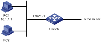
Figure 1-1 Network diagram for basic ACL configuration
III. Configuration procedure
& Note:
Only the commands related to the ACL configuration are listed below.
1) Define the time range
# Define a periodic time range that takes effect from 8:00 to 18:00 everyday.
<H3C> system-view
[H3C] time-range test 8:00 to 18:00 daily
2) Define an ACL for packets with the source IP address of 10.1.1.1.
# Create ACL 2000 and enter ACL 2000 view.
[H3C] acl number 2000
# Define an access rule to deny packets with their source IP addresses being 10.1.1.1.
[H3C-acl-basic-2000] rule 1 deny source 10.1.1.1 0 time-range test
[H3C-acl-basic-2000] quit
3) Apply the ACL on the port
# Apply ACL 2000 on the port.
[H3C] interface Ethernet2/0/1
[H3C-Ethernet2/0/1] qos
[H3C-qoss-Ethernet2/0/1] packet-filter inbound ip-group 2000
1.11.2 Advanced ACL Configuration Example
I. Network requirements
Different departments of an enterprise are interconnected on the intranet through the ports of a switch. The IP address of the wage query server is 192.168.1.2. Devices of the R&D department are connected to Ethernet2/0/1 of the switch. Apply an ACL to deny requests sourced from the R&D department and destined for the wage server during the working hours (8:00 to 18:00) of the working days.
II. Network diagram
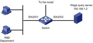
Figure 1-2 Network diagram for advanced ACL configuration
III. Configuration procedure
& Note:
Only the commands related to the ACL configuration are listed below.
1) Define the time range
# Define a periodic time range that takes effect from 8:00 to 18:00 every working day.
<H3C> system-view
[H3C] time-range test 8:00 to 18:00 working-day
2) Define an ACL for filtering requests destined for the wage server.
# Create ACL 3000 and enter ACL 3000 view.
[H3C] acl number 3000
# Define an ACL rule for requests destined for the wage server.
[H3C-acl-adv-3000] rule 1 deny ip destination 192.168.1.2 0 time-range test
[H3C-acl-adv-3000] quit
3) Apply the ACL on a port.
# Apply ACL 3000 on Ethernet 2/0/1.
[H3C] interface Ethernet2/0/1
[H3C-Ethernet2/0/1] qos
[H3C-qoss-Ethernet2/0/1] packet-filter inbound ip-group 3000
1.11.3 Layer 2 ACL Configuration Example
I. Network requirements
Through Layer 2 ACL configuration, packets with the source MAC address of 0011-0011-0101 and destination MAC address of 0011-0011-0303 are to be filtered within the time range from 8:00 to 18:00 everyday. Apply this ACL on Ethernet 2/0/1.
II. Network diagram
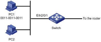
Figure 1-3 Network diagram for Layer 2 ACL configuration
III. Configuration procedure
& Note:
Only the commands related to the ACL configuration are listed below.
1) Define the time range
# Define the periodic time range from 8:00 to 18:00 everyday.
<H3C> system-view
[H3C] time-range test 8:00 to 18:00 daily
2) Define an ACL rule for packets with the source MAC address of 0011-0011-0101 and destination MAC address of 0011-0011-0303.
# Create ACL 4000 and enter ACL 4000 view.
[H3C] acl number 4000
# Define an ACL rule to deny packets with the source MAC address of 0011-0011-0101 and destination MAC address of 0011-0011-0303, specifying the time range named test for the ACL rule.
[H3C-acl-link-4000] rule 1 deny ingress 0011-0011-0101 ffff-ffff-ffff egress 0011-0011-0303 ffff-ffff-ffff time-range test
[H3C-acl-link-4000] quit
3) Apply the ACL on a port.
# Apply ACL 4000 on the Ethernet 2/0/1.
[H3C] interface Ethernet 2/0/1
[H3C-Ethernet2/0/1] qos
[H3C-qoss-Ethernet2/0/1] packet-filter inbound link-group 4000
1.11.4 User-Defined ACL Configuration Example
I. Network requirements
Create a user-defined ACL to deny all TCP packets within the time range from 8:00 to 18:00 everyday. Apply the user-defined ACL on Ethernet 2/0/1.
II. Network diagram
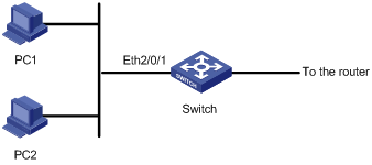
Figure 1-4 Network diagram for user-defined ACL configuration
III. Configuration procedure
& Note:
Only the commands related to the ACL configuration are listed below.
1) Define the time range.
# Define the periodic time range from 8:00 to 18:00 everyday.
[H3C] time-range test 8:00 to 18:00 daily
2) Create an ACL rule to filter TCP packets.
# Create ACL 5000 and enter ACL 5000 view.
[H3C] acl number 5000
# Define a rule for TCP packets.
[H3C-acl-user-5000] rule 1 deny 06 ff 27 time-range test
3) Apply the ACL on a port.
# Apply ACL 5000 on port Ethernet 2/0/1.
[H3C] interface Ethernet2/0/1
[H3C-Ethernet2/0/1] qos
[H3C-qosb-Ethernet2/0/1] packet-filter inbound user-group 5000