- Table of Contents
-
- H3C S7500 Series Operation Manual(Release 3100 Series)-(V1.04)
- 00-1Cover
- 00-2Overview
- 01-CLI Configuration
- 02-Login Configuration
- 03-Configuration File Management Configuration
- 04-VLAN Configuration
- 05-Extended VLAN Application Configuration
- 06-IP Address-IP Performance-IPX Configuration
- 07-GVRP Configuration
- 08-QinQ Configuration
- 09-Port Basic Configuration
- 10-Link Aggregation Configuration
- 11-Port Isolation Configuration
- 12-Port Binding Configuration
- 13-DLDP Configuration
- 14-MAC Address Table Configuration
- 15-MSTP Configuration
- 16-Routing Protocol Configuration
- 17-Multicast Configuration
- 18-802.1x Configuration
- 19-AAA-RADIUS-HWTACACS-EAD Configuration
- 20-Traffic Accounting Configuration
- 21-VRRP-HA Configuration
- 22-ARP Configuration
- 23-DHCP Configuration
- 24-ACL Configuration
- 25-QoS Configuration
- 26-Mirroring Configuration
- 27-Cluster Configuration
- 28-PoE Configuration
- 29-UDP-Helper Configuration
- 30-SNMP-RMON Configuration
- 31-NTP Configuration
- 32-SSH Terminal Service Configuration
- 33-File System Management Configuration
- 34-FTP and TFTP Configuration
- 35-Information Center Configuration
- 36-DNS Configuration
- 37-System Maintenance and Debugging Configuration
- 38-HWPing Configuration
- 39-RRPP Configuration
- 40-NAT-Netstream-Policy Routing Configuration
- 41-Telnet Protection Configuration
- 42-Hardware-Dependent Software Configuration
- Related Documents
-
| Title | Size | Download |
|---|---|---|
| 21-VRRP-HA Configuration | 235 KB |
Table of Contents
1.1.3 Introduction to Backup Group
1.2.1 VRRP Configuration Task List
1.2.2 Configuring a Virtual Router IP Address
1.2.3 Configuring Backup Group-Related Parameters
1.3 Displaying and Maintaining VRRP
1.4 VRRP Configuration Examples
1.4.1 Single-VRRP Backup Group Configuration
1.4.2 VRRP Tracking Interface Configuration
1.4.3 Multiple-VRRP Backup Group Configuration
2.2.1 HA Configuration Overview
2.2.2 Setting the Slave Board Restart Manually
2.2.3 Performing the Master/slave Switchover Manually
2.2.4 Enabling Automatic Synchronization
2.2.5 Synchronizing the Configuration File of the System Manually
Chapter 1 VRRP Configuration
When configuring VRRP, go to these sections for information you are interested in:
l Displaying and Maintaining VRRP
1.1 VRRP Overview
Virtual Router Redundancy Protocol (VRRP) is a fault-tolerant protocol.
As shown in Figure 1-1, in general,
l A default route (for example, the next hop address of the default route is 10.100.10.1, as shown in the following figure) is configured for every host on a network.
l The packets destined for the external network segments and sourced from these hosts go through the default routes to the Layer 3 Switch, implementing communication between these hosts and the external network.
l If Switch fails, all the hosts on this segment taking Switch as the next-hop through the default routes are cut off from the external network.
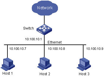
Figure 1-1 LAN networking
VRRP, designed for LANs with multicast and broadcast capabilities (such as Ethernet), settles the problem caused by switch failures.
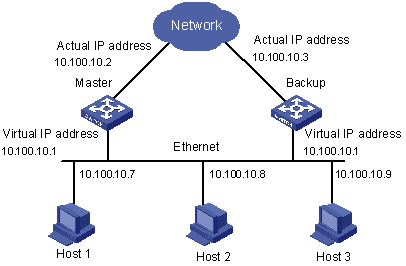
VRRP combines a group of LAN switches, including a master switch and several backup switches, into a virtual router, or a backup group.
The switches in a backup group have the following features:
l This virtual router has its own IP address: 10.100.10.1 (which can be the interface address of a switch within the backup group).
l The switches within the backup group have their own IP addresses (such as 10.100.10.2 for the master switch and 10.100.10.3 for the backup switch).
l Hosts on the LAN only know the IP address of this virtual router, that is, 10.100.10.1, but not the specific IP addresses 10.100.10.2 of the master switch and 10.100.10.3 of the backup switch.
l Hosts in the LAN use the IP address of the virtual router (that is, 10.100.10.1) as their default next-hop IP addresses.
Therefore, hosts within the network will communicate with the other networks through this virtual router.
If the master switch in the backup group goes down, the backup switch with the highest priority functions as the new master switch to guarantee normal communication between the hosts and the external networks. This ensures the communications between the hosts and the external networks.
1.1.1 Virtual Router Overview
After you enable VRRP on the switches of a backup group, a virtual router is formed. You can perform related configuration on the virtual router.
I. Configuring a virtual router IP address
The IP address of the virtual router can be an unassigned IP address of the network segment where the backup group is located or the interface IP address of a member switch in the backup group. Virtual router IP address has the following features:
l You can specify the virtual router IP address as the IP address used by a member switch in the backup group. In this case, the switch is called an IP address owner.
l A backup group is established if it is assigned an IP address for the first time. If you then add other IP addresses to the backup group, the IP addresses are added to the virtual router IP address list of the backup group.
l The virtual router IP address and the IP addresses used by the member switches in a backup group must belong to the same network segment. If not, the backup group will be in the initial state (the state before you configure the VRRP on the switches of the group). In this case, VRRP does not take effect.
l A backup group is removed if all its virtual router IP addresses are removed. In this case, all the configurations performed for the backup group get ruined.
According to the standard VRRP, you will fail to use the ping command to ping the IP address of a virtual router. So the hosts connected to a switch in a backup group cannot judge whether an IP address is used by the backup group with ping command. If the IP address of a host is also used by the virtual router, all packets destined for the network segment will be forwarded to the host. In this case, data in this network segment cannot be forwarded properly.
Before enabling VRRP feature on an S7500 switch, you can enable the switches in a backup group to respond the ping operations destined for the virtual router IP addresses. Therefore the above incident can be avoided. If VRRP is already enabled, the system does not support this configuration.
II. Mapping Virtual IP Addresses to MAC Addresses
An S7500 switch provides the following functions in addition to forwarding data correctly.
l You can map multiple virtual IP addresses of the backup group to a virtual MAC address as needed. You can also map virtual IP addresses to the MAC address of a switch routing interface.
l You need to map the IP addresses of the backup group to the MAC addresses before enabling VRRP feature on an S7500 switch. If VRRP is already enabled, the system does not support this configuration.
By default, virtual router IP addresses are mapped to the virtual MAC address of a backup group.
& Note:
When you map a virtual IP address to the virtual MAC address on an S7500 switch, the number of backup groups that can be configured on a VLAN interface is determined by the chips used. Refer to device specification for detail.
1.1.2 Introduction to Backup Group
I. Configurations available on switches in a backup group
VRRP can group switches in a LAN into a virtual router, which is also known as a backup group.
You can perform the following configuration on an S7500 switch that belongs to a backup group.
Complete these tasks to configure switches in a backup group:
|
Task |
Remarks |
|
Required |
|
|
Required |
|
|
Configuring authentication type and authentication key for a switch in a backup group |
Optional |
|
Required |
|
|
Configuring the VLAN interfaces/Ethernet ports to be tracked for a backup group |
Required |
II. Configuring switch priority
You can configure the priority of a switch in a backup group. VRRP will determine the status of each switch in a backup group according to the priority of the switch. The master switch in a backup group is the one currently with the highest priority.
Switch priority ranges from 0 to 255 (a larger number indicates a higher switch priority) and defaults to 100. Note that only 1 through 254 are available to users. Switch priority of 255 is reserved for IP address owners.
& Note:
The priority of the IP address owner is fixed to 255.
III. Configuring preemptive mode for a switch in a backup group
As long as a switch in the backup group becomes the master switch, other switches, even if they are configured with a higher priority later, do not preempt the master switch unless they operate in preemptive mode. The switch operating in preemptive mode will become the master switch when it finds its priority is higher than that of the current master switch, and the former master switch becomes a backup switch accordingly.
You can configure an S7500 switch to operate in preemptive mode. You can also set the delay period. A backup switch waits for a period of time (the delay period) before becoming a master switch. Setting a delay period aims at:
In an unstable network, backup switches in a backup group possibly cannot receive packets from the master in time due to network congestions even if the master operates properly. This causes the master of the backup group being determined frequently. With the configuration of delay period, the backup switch will wait for a while if it does not receive packets from the master switch in time. A new master is determined only after the backup switches do not receive packets from the master switch after the specified delay time.
IV. Configuring authentication type and authentication key for a switch in a backup group
VRRP provides following authentication types:
l simple: Simple character authentication
l md5: MD5 authentication
In a network under possible security threat, the authentication type can be set to simple. Then the switch adds the authentication key into the VRRP packets before transmitting them. The receiver will compare the authentication key of the packet with the locally configured one. If they are the same, the packet will be taken as a true and legal one. Otherwise it will be regarded as an illegal packet and be discarded. In this case, a simple authentication key should not exceed eight characters.
In a vulnerable network, the authentication type can be set to md5. The switch then uses the authentication type provided by the Authentication Header, and MD5 algorithm to authenticate the VRRP packets. In this case, you need to set an authentication key in plain text comprising up to eight characters or an authentication key of a 24-character encrypted string.
Packets that fail to pass the authentication are discarded. The switch then sends trap packets to the network management system.
V. Configuring VRRP timer
The master switch advertises its normal operation state to the switches within the VRRP backup group by sending VRRP packets once in each specified interval (determined by the adver-interval argument). If the backup switches do not receive VRRP packets from the master after a specific period (determined by the master-down-interval argument), they consider the master is down and initiates the process to determine the master switch.
You can adjust the frequency in which a master sends VRRP packets by setting the corresponding VRRP timers (that is, the adver-interval argument). The master-down-interval argument is usually three times of the adver-interval argument. Excessive network traffic or differences between the timers of different switches will result in master-down-interval timing out and state changing abnormally. Such problems can be solved through prolonging the adver-interval and setting delay time. If you configure the preemption delay for a backup switch, the switch preempts the master after the period specified by the preemption delay if it does not receive a VRRP packet from the master for the period specified by the master-down-interval argument.
VI. Configuring the VLAN interfaces/Ethernet ports to be tracked for a backup group
The VLAN interface/Ethernet port tracking function expands the backup group function. With this function enabled, the backup group function is provided not only when the interface where the backup group resides fails, but also when other interfaces/Ethernet ports are unavailable. By executing the related command you can track an interface/Ethernet port.
When a tracked VLAN interface goes down, the priority of the switch owning the interface will reduce automatically by a specified value (the value-reduced argument). If the switches with their priorities higher than that of the current master switch exist in the backup group, a new master switch will be then determined.
& Note:
l The Ethernet port tracked can be in or out of the VLAN in whose interface the backup group resides.
l If a switch is the IP address owner, the VLAN interface/Ethernet port tracking function can not be enabled for the switch.
l If a tracked VLAN interface/Ethernet port goes down, when it is up again, the priority of the corresponding switch is automatically restored.
l Each backup group can track up to eight VLAN interfaces/Ethernet ports.
1.2 VRRP Configuration
1.2.1 VRRP Configuration Task List
Complete the following tasks to configure VRRP:
|
Task |
Remarks |
|
Required |
|
|
Required |
1.2.2 Configuring a Virtual Router IP Address
The following table lists the operations to configure a virtual router IP address (suppose you have correctly configured the relation between the port and VLAN):
Follow these steps to configure a virtual router IP address:
|
To do… |
Use the command… |
Remarks |
|
Enter system view |
system-view |
— |
|
Configure that the virtual IP address can be pinged |
vrrp ping-enable |
Optional By default, the virtual IP address cannot be pinged. |
|
Map the virtual router IP address to a MAC address |
vrrp method { real-mac | virtual-mac } |
Optional By default, the virtual IP address of a backup group is mapped to a virtual router IP address. |
|
Create a VLAN |
vlan vlan-id |
— This operation creates the VLAN to which the backup group corresponds. The vlan-id argument is the ID of the VLAN. |
|
Return to system view |
quit |
— |
|
Enter VLAN interface view |
interface Vlan-interface vlan-id |
— |
|
Configure a virtual router IP address |
vrrp vrid virtual-router-id virtual-ip virtual-address |
Optional |
1.2.3 Configuring Backup Group-Related Parameters
Follow these steps to configure backup group-related parameters:
|
To do… |
Use the command… |
Remarks |
|
Enter system view |
system-view |
— |
|
Create a VLAN |
vlan vlan-id |
— |
|
Return to system view |
quit |
— |
|
Enter VLAN interface view |
interface Vlan-interface valn-id |
— |
|
Configure the priority of the backup group |
vrrp vrid virtual-router-id priority priority |
Optional By default, the priority of a backup group is 100. |
|
Configure the preemptive mode and delay period for the backup group |
vrrp vrid virtual-router-id preempt-mode [ timer delay delay-value ] |
Optional By default, a backup group operates in the preemptive mode. |
|
Configure the authentication type and authentication key |
vrrp authentication-mode authentication-type authentication-key |
Optional By default, no authentication is configured for a backup group. |
|
Configure the VRRP timer |
vrrp vrid virtual-router-id timer advertise adver-interval |
Optional By default, the interval for the master switch in a backup group to send VRRP packets is 1 second. |
|
Specify the interface/Ethernet port to be tracked |
vrrp vrid virtual-router-id track interface-type interface-number [ reduced value-reduced ] |
Optional value-reduced: Value by which the priority is to be reduced. By default, this value is 10. |
1.3 Displaying and Maintaining VRRP
|
Use the command… |
Remarks |
|
|
Display VRRP state information and statistics information |
display vrrp [ interface vlan-interface vlan-id | statistics [ vlan-interface vlan-id ] ] [ virtual-router-id ] |
Available in any view. |
|
Clear VRRP statistics |
reset vrrp statistics [ vlan-interface vlan-id ] [ virtual-router-id ] |
Available in user view. |
|
Enable VRRP debugging function |
debugging vrrp { state | packet } |
Available in user view. |
1.4 VRRP Configuration Examples
1.4.1 Single-VRRP Backup Group Configuration
I. Network requirements
Host A uses the VRRP virtual router comprising switch A and switch B as its default gateway to visit host B on the Internet.
The information about the VRRP backup group is as follows:
l VRRP backup group ID: 1
l Virtual router IP address: 202.38.160.111
l Master switch: Switch A
l Backup switch: Switch B
l Preemptive mode: enabled
Table 1-1 Network description
|
Switch |
Ethernet port connecting to Host A |
IP address of the VLAN interface |
Switch priority in the backup group |
|
|
LSW-A |
Ethernet 2/0/6 |
202.38.160.1/24 |
110 |
Enabled |
|
LSW-B |
Ethernet 2/0/5 |
202.38.160.2/24 |
100 (default) |
Enabled |
II. Network diagram
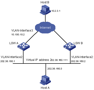
Figure 1-3 Network diagram for single-VRRP backup group configuration
III. Configuration procedure
l Configure Switch A.
# Configure VLAN 2.
<LSW-A> system-view
[LSW-A] vlan 2
[LSW-A-vlan2] port Ethernet 2/0/6
[LSW-A-vlan2] quit
[LSW-A] interface Vlan-interface 2
[LSW-A-Vlan-interface2] ip address 202.38.160.1 255.255.255.0
[LSW-A-Vlan-interface2] quit
# Enable a backup group to respond to ping operations destined for its virtual router IP address.
[LSW-A] vrrp ping-enable
# Create a backup group.
[LSW-A] interface vlan 2
[LSW-A-Vlan-interface2] vrrp vrid 1 virtual-ip 202.38.160.111
# Set the priority for the backup group.
[LSW-A-Vlan-interface2] vrrp vrid 1 priority 110
# Configure the preemptive mode for the backup group.
[LSW-A-Vlan-interface2] vrrp vrid 1 preempt-mode
l Configure Switch B.
# Configure VLAN 2.
<LSW-B> system-view
System View: return to User View with Ctrl+Z.
[LSW-B] vlan 2
[LSW-B-Vlan2] port Ethernet 2/0/5
[LSW-B-vlan2] quit
[LSW-B] interface Vlan-interface 2
[LSW-B-Vlan-interface2] ip address 202.38.160.2 255.255.255.0
[LSW-B-Vlan-interface2] quit
# Enable a backup group to respond to ping operations destined for its virtual router IP address.
[LSW-B] vrrp ping-enable
# Create a backup group.
[LSW-B] interface vlan 2
[LSW-B-Vlan-interface2] vrrp vrid 1 virtual-ip 202.38.160.111
# Configure the preemptive mode for the backup group.
[LSW-B-Vlan-interface2] vrrp vrid 1 preempt-mode
The IP address of the default gateway of Host A can be configured to be 202.38.160.111.
Normally, Switch A functions as the gateway, but when Switch A is turned off or fails, Switch B will function as the gateway instead.
Configure Switch A to operate in preemptive mode, so that it can resume its gateway function as the master switch after recovery.
1.4.2 VRRP Tracking Interface Configuration
I. Network requirements
Even when Switch A is still functioning, Switch B (with another link to connect with the outside) can function as a gateway when Switch A’s interface connecting to Internet does not function properly. This can be implemented by enabling the VLAN interface tracking function.
The VRRP backup group ID is set to 1, with configurations of authorization key and timer.
II. Network diagram
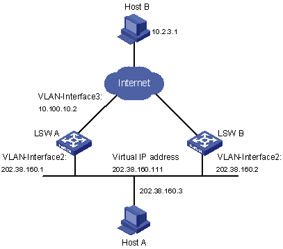
Figure 1-4 Network diagram for interface tracking configuration
III. Configuration procedure
l Configure Switch A.
# Configure VLAN 2.
<LSW-A> system-view
System View: return to User View with Ctrl+Z.
[LSW-A] vlan 2
[LSW-A-vlan2] port Ethernet 2/0/6
[LSW-A-vlan2] quit
[LSW-A] interface Vlan-interface 2
[LSW-A-Vlan-interface2] ip address 202.38.160.1 255.255.255.0
[LSW-A-Vlan-interface2] quit
# Configure that the virtual router can be pinged.
[LSW-A] vrrp ping-enable
# Create a backup group.
[LSW-A] interface Vlan-interface 2
[LSW-A-Vlan-interface2] vrrp vrid 1 virtual-ip 202.38.160.111
# Set the priority for the backup group.
[LSW-A-Vlan-interface2] vrrp vrid 1 priority 110
# Set the authentication type for the backup group to md5, and the password to abc123.
[LSW-A-Vlan-interface2] vrrp authentication-mode md5 abc123
# Configure that the master switch to send VRRP packets once every 5 seconds.
[LSW-A-Vlan-interface2] vrrp vrid 1 timer advertise 5
# Set the tracked VLAN interface.
[LSW-A-Vlan-interface2] vrrp vrid 1 track Vlan-interface 3 reduced 30
l Configure Switch B.
# Configure VLAN 2.
<LSW-B> system-view
System View: return to User View with Ctrl+Z.
[LSW-B] vlan 2
[LSW-B-vlan2] port Ethernet 2/0/5
[LSW-B-vlan2] quit
[LSW-B] interface Vlan-interface 2
[LSW-B-Vlan-interface2] ip address 202.38.160.2 255.255.255.0
[LSW-B-Vlan-interface2] quit
# Configure that the virtual router can be pinged.
[LSW-B] vrrp ping-enable
# Create a backup group.
[LSW-B] interface Vlan-interface 2
[LSW-B-Vlan-interface2] vrrp vrid 1 virtual-ip 202.38.160.111
# Set the authentication key for the backup group.
[LSW-B-Vlan-interface2] vrrp authentication-mode md5 abc123
# Set the master to send VRRP packets once every 5 seconds.
[LSW-B-Vlan-interface2] vrrp vrid 1 timer advertise 5
Normally, Switch A functions as the gateway, but when VLAN-interface 3 on Switch A goes down, its priority will be reduced by 30, lower than that of Switch B so that Switch B will preempt the master for gateway services.
When VLAN-interface 3 recovers, Switch A will resume its gateway function as the master.
1.4.3 Multiple-VRRP Backup Group Configuration
I. Network requirements
A switch can function as backup switches of multiple backup groups.
Multiple-backup group configuration can implement load balancing. For example, Switch A operates as the master switch of backup group 1 and a backup switch in backup group 2. Similarly, Switch B operates as the master switch of backup group 2 and a backup switch in backup group 1. Some hosts in the network take virtual router 1 as the gateway, while others take virtual router 2 as the gateway. In this way, both load balancing and mutual backup are implemented.
II. Network diagram
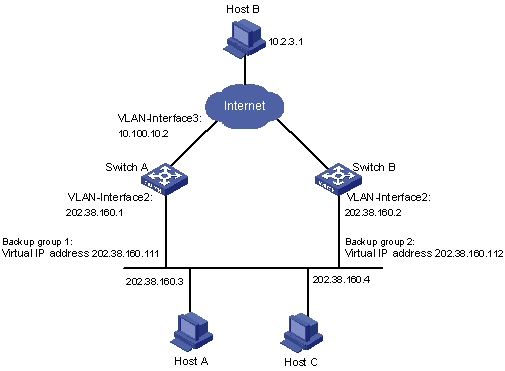
Figure 1-5 Network diagram for multiple-VRRP backup group configuration
III. Configuration procedure
l Configure Switch A.
# Configure VLAN 2.
<LSW-A> system-view
System View: return to User View with Ctrl+Z.
[LSW-A] vlan 2
[LSW-A-vlan2] port Ethernet 2/0/6
[LSW-A-vlan2] quit
[LSW-A] interface Vlan-interface 2
[LSW-A-Vlan-interface2] ip address 202.38.160.1 255.255.255.0
# Create backup group 1.
[LSW-A-Vlan-interface2] vrrp vrid 1 virtual-ip 202.38.160.111
# Set the priority for backup group 1.
[LSW-A-Vlan-interface2] vrrp vrid 1 priority 150
# Create backup group 2.
[LSW-A-Vlan-interface2] vrrp vrid 2 virtual-ip 202.38.160.112
l Configure Switch B.
# Configure VLAN 2.
<LSW-B> system-view
System View: return to User View with Ctrl+Z.
[LSW-B] vlan 2
[LSW-B-vlan2] port Ethernet 2/0/6
[LSW-B-vlan2] quit
[LSW-B] interface vlan-interface 2
[LSW-B-Vlan-interface2] ip address 202.38.160.2 255.255.255.0
# Create backup group 1.
[LSW-B-Vlan-interface2] vrrp vrid 1 virtual-ip 202.38.160.111
# Create backup group 2.
[LSW-B-Vlan-interface2] vrrp vrid 2 virtual-ip 202.38.160.112
# Set the priority for backup group 2.
[LSW-B-Vlan-interface2] vrrp vrid 2 priority 110
& Note:
Normally, multiple backup groups are used in actual networking.
1.5 Troubleshooting VRRP
You can locate VRRP problems through the configuration and debugging information. Here are some possible failures you might meet and the corresponding troubleshooting methods.
I. Symptom 1: Frequent prompts of configuration errors on the console
This indicates that incorrect VRRP packets are received. It may be because of the inconsistent configuration of the switches within the backup group, or the attempt of other devices sending out illegal VRRP packets. The first possible fault can be solved through modifying the configuration. And as the second possibility is caused by the malicious attempt of some devices, non-technical measures should be resorted to.
II. Symptom 2: More than one master existing within a backup group
There are also 2 reasons. One is short time coexistence of many master switches, which is normal and needs no manual intervention. Another is the long time coexistence of many master switches, which may be because the original master switch and other member switches in a backup group cannot receive VRRP packets from each other, or receive some illegal packets.
To solve such a problem, an attempt should be made to ping among these masters and if such an attempt fails, check the connectivity between related devices. If they can be pinged through, check VRRP configuration. For the configuration of a VRRP backup group, complete consistency for the number of virtual IP addresses, each virtual IP address, timer duration and authentication type configured on each member switch must be guaranteed.
III. Symptom 3: VRRP state of a switch changes repeatedly
Such problems occur when the backup group timer duration is too short. They can be solved through prolonging the duration or configuring the preemption delay period.
Chapter 2 HA Configuration
When configuring HA, go to these sections for information you are interested in:
2.1 HA Overview
S7506R supports high availability (HA) feature. This feature is to achieve a high availability of the system and to recover the system quickly in the event of failures so as to shorten the mean time between failure (MTBF).
The functions of HA are mainly implemented by the application running on SRPU board. An S7506R switch has two SRPUs, which are working in the master/slave mode: one board works in master mode as the master board, the other works in slave mode as a backup board. If the master/slave system detects a fault in the master board, a master/slave switchover will be performed automatically. The slave board will try to connect with and control the system bus while the original master board will try to disconnect from the bus. Thus, the master/slave switchover of the active system is completed, and at the same time the original master board is reset to function as the slave board. Therefore, even if the master board fails, the slave board can also take its role to ensure the normal operation of the S7506R switch.
S7506R supports hot swap of SRPUs. The hot swap of master boards will cause master/slave switchover.
S7506R supports manually master/slave switchover. You can change the current board state manually by executing commands.
![]() Caution:
Caution:
The HA feature of the S7506R switches can realize the software upgrade of the two SRPUs with at least one SRPU being active. However, the SRPU and the LPU of the Ethernet switches must be identical in their software version, otherwise they cannot work normally. Therefore, during the upgrade, you are recommended to restart the whole switch after the SRPU executes the boot boot-loader command to ensure normal operating of the switch.
The configuration file of the slave board is copied from the master board in real time, which can ensure that the slave system continues to operate in the same configuration as that of the original active system after the master/slave switchover. S7506R supports automatic synchronization of the configuration file. The active system stores its configuration file and backs up the configuration file to the slave system simultaneously when the master's configuration file is modified, so as to ensure the consistency of the configurations of the active system and slave system. And you can also use command to manually synchronize the configuration file of the master and slave board.
Besides, the system can monitor the power supply and the operating environment of the system and give timely alarms to avoid the escalation of failures and ensure safe operation of the system.
2.2 HA Configuration
2.2.1 HA Configuration Overview
Complete the following tasks to configure HA:
|
Task |
Remarks |
|
Required |
|
|
Required |
|
|
Required |
|
|
Required |
& Note:
l When the S7506R starts, if you log in to the slave board, it will take about 3 minutes before you can see the system prompt. During the 3 minutes, the slave board does not respond to any operation. This is system protective design for avoiding switching shake.
l You cannot execute any command on the slave board until the slave board switches to the master.
l The master board will back up the configuration to slave board step by step as soon as the system is up, which is a quick process. In this process, the system will give a prompt on both master board and slave board if you press the “enter” key on the terminal, at the time, you cannot execute any command on the master board. After the block backup, the master board keeps doing the real-time backup with the slave board and you can execute all commands on the master board.
l You must keep the consistency of the version of the master and slave board.
2.2.2 Setting the Slave Board Restart Manually
When the slave board works normally, you can set the slave system restart manually.
Perform the following operation to set slave board restart manually:
|
To do… |
Use the command… |
Remarks |
|
Set slave board restart manually |
slave restart |
Optional Available in user view |
2.2.3 Performing the Master/slave Switchover Manually
When the slave board is available and the master is in real-time backup state, you can inform the slave board of a master/slave switchover by using a command if you expect the slave board to operate in place of the master board. After the switchover, the slave board will control the system and the original master board will reset automatically.
Follow the following step to perform the master/slave switchover manually:
|
To do… |
Use the command… |
Remarks |
|
Perform the master/slave switchover manually |
slave switchover |
Optional Available in user view |
2.2.4 Enabling Automatic Synchronization
S7506R supports automatic synchronization. The master board stores its configuration file and backups the configuration file to the slave board simultaneously when the master's configuration file is modified, so as to ensure the consistency of the configurations of the master system and slave system.
You can enable/disable automatic synchronization of the S7506R.
Follow these steps to enable automatic synchronization:
|
To do… |
Use the command… |
Remarks |
|
Enter system view |
system-view |
— |
|
Enable automatic synchronization |
slave auto-update config |
Optional |
2.2.5 Synchronizing the Configuration File of the System Manually
The system can synchronize the configuration files on the master and slave boards automatically. If you want to synchronize them, you can do it manually by using the command below.
Follow the step to synchronize the configuration file manually:
|
To do… |
Use the command… |
Remarks |
|
Synchronize the configuration file manually |
slave update configuration |
Optional Available in user view. |
This operation can back up the configuration file to the slave board only when the slave system operates normally. The configuration file will be fully copied at each time the operation is executed.
2.3 Displaying HA
|
To do… |
Use the command… |
Remarks |
|
Display the switchover status of the master/slave board |
display switchover state [ slot-id ] |
Available in any view. |