- Table of Contents
-
- H3C S7500 Series Operation Manual(Release 3100 Series)-(V1.04)
- 00-1Cover
- 00-2Overview
- 01-CLI Configuration
- 02-Login Configuration
- 03-Configuration File Management Configuration
- 04-VLAN Configuration
- 05-Extended VLAN Application Configuration
- 06-IP Address-IP Performance-IPX Configuration
- 07-GVRP Configuration
- 08-QinQ Configuration
- 09-Port Basic Configuration
- 10-Link Aggregation Configuration
- 11-Port Isolation Configuration
- 12-Port Binding Configuration
- 13-DLDP Configuration
- 14-MAC Address Table Configuration
- 15-MSTP Configuration
- 16-Routing Protocol Configuration
- 17-Multicast Configuration
- 18-802.1x Configuration
- 19-AAA-RADIUS-HWTACACS-EAD Configuration
- 20-Traffic Accounting Configuration
- 21-VRRP-HA Configuration
- 22-ARP Configuration
- 23-DHCP Configuration
- 24-ACL Configuration
- 25-QoS Configuration
- 26-Mirroring Configuration
- 27-Cluster Configuration
- 28-PoE Configuration
- 29-UDP-Helper Configuration
- 30-SNMP-RMON Configuration
- 31-NTP Configuration
- 32-SSH Terminal Service Configuration
- 33-File System Management Configuration
- 34-FTP and TFTP Configuration
- 35-Information Center Configuration
- 36-DNS Configuration
- 37-System Maintenance and Debugging Configuration
- 38-HWPing Configuration
- 39-RRPP Configuration
- 40-NAT-Netstream-Policy Routing Configuration
- 41-Telnet Protection Configuration
- 42-Hardware-Dependent Software Configuration
- Related Documents
-
| Title | Size | Download |
|---|---|---|
| 08-QinQ Configuration | 119 KB |
1.2.1 Configuration Prerequisites
1.3 Displaying QinQ Configuration
1.4 QinQ Configuration Example
Chapter 2 Selective QinQ Configuration
2.1.1 Selective QinQ Implementation
2.2 Selective QinQ Configuration
2.2.1 Configuration Prerequisites
2.2.2 Configuring Selective QinQ
2.2.3 Selective QinQ Configuration Example
Chapter 1 QinQ Configuration
1.1 QinQ Overview
1.1.1 Introduction to QinQ
The QinQ function enables packets to be transmitted across the operators’ backbone networks with VLAN tags of private networks encapsulated in those of public networks. In public networks, packets of this type are transmitted by their outer VLAN tags (that is, the VLAN tags of public networks). And those of private networks which are encapsulated in the VLAN tags of public networks are shielded.
Figure 1-1 illustrates the structure of a single-tagged packet.
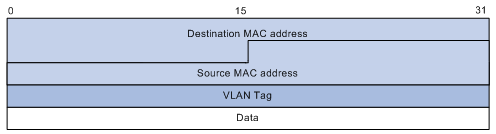
Figure 1-1 Structure of a single-tagged packet
Figure 1-2 illustrates the structure of a double-tagged packet.
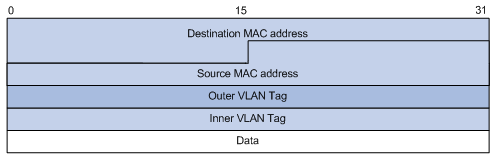
Figure 1-2 Structure of a double-tagged packet
Compared with MPLS-based Layer 2 VPN, QinQ has the following features:
l It provides simpler Layer 2 VPN tunnels.
l QinQ can be implemented through static configurations only, without the support of signaling protocols.
The QinQ function provides you with the following benefits:
l Saves public network VLAN ID resources.
l You can have your private network VLAN IDs independent of public network VLAN IDs.
l Provides simpler Layer 2 VPN solutions for small-sized MANs or intranets.
1.1.2 Implementation of QinQ
QinQ can be implemented by enabling the QinQ function on ports.
With the QinQ function enabled, a received packet is tagged with the default VLAN tag of the receiving port no matter whether or not the packet already carries a VLAN tag. If the packet already carries a VLAN tag, the packet becomes a double-tagged packet. Otherwise, the packet becomes a packet carrying the default VLAN tag of the port.
1.2 QINQ Configuration
1.2.1 Configuration Prerequisites
1.2.2 Configuring QinQ
Follow these steps to configure QinQ:
|
To do… |
Use the command… |
Remarks |
|
Enter system view |
system-view |
— |
|
Enter Ethernet port view |
interface interface-type interface-number |
— |
|
Enable QinQ for the port |
vlan-vpn enable |
Required By default, QinQ is disabled on a port. |
![]() Caution:
Caution:
The LS82GT20 and LS82GP20 LPUs do not support the QinQ feature.
1.3 Displaying QinQ Configuration
|
To do… |
Use the command… |
Remarks |
|
Display the QinQ configuration of all the ports |
display port vlan-vpn |
This command can be executed in any view. |
1.4 QinQ Configuration Example
I. Network Requirements
l Switch A, Switch B, and Switch C are S7500 switches.
l Two user networks are connected to the Ethernet 2/0/1 ports of Switch A and Switch C respectively.
l Switch B only permits the packets of VLAN 10.
l It is required that packets of the VLANs other than VLAN 10 be exchanged between the networks connected to Switch A and Switch C.
II. Network Diagram
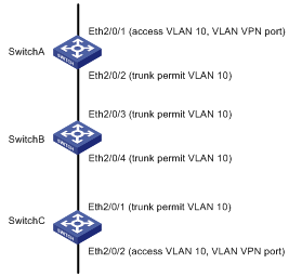
Figure 1-3 Network diagram for QinQ configuration
III. Configuration Procedure
1) Configure Switch A and Switch C.
As the configurations performed on Switch A and Switch C are the same, configurations on Switch C are omitted.
# Configure Ethernet 2/0/2 as a trunk port. Add the port to VLAN 10.
<SwitchA> system-view
[SwitchA] vlan 10
[SwitchA-vlan10] quit
[SwitchA] interface Ethernet2/0/2
[SwitchA-Ethernet2/0/2] port link-type trunk
[SwitchA-Ethernet2/0/2] port trunk permit vlan 10
# Enable QinQ for Ethernet 2/0/1 of Switch A. Add the port to VLAN 10.
[SwitchA-Ethernet2/0/2] quit
[SwitchA] interface Ethernet2/0/1
[SwitchA-Ethernet2/0/1] port access vlan 10
[SwitchA-Ethernet2/0/1] vlan-vpn enable
[SwitchA-Ethernet2/0/1] quit
2) Configure Switch B.
# Configure Ethernet 2/0/3 and Ethernet 2/0/4 of Switch B as trunk ports. Add the two ports to VLAN 10.
<SwitchB> system-view
[SwitchB] vlan 10
[SwitchB-vlan10] quit
[SwitchB] interface Ethernet 2/0/3
[SwitchB-Ethernet2/0/3] port link-type trunk
[SwitchB-Ethernet2/0/3] port trunk permit vlan 10
[SwitchB-Ethernet2/0/3] quit
[SwitchB] interface Ethernet 2/0/4
[SwitchB-Ethernet2/0/4] port link-type trunk
[SwitchB-Ethernet2/0/4] port trunk permit vlan 10
& Note:
The following describes how a packet is forwarded from Switch A to Switch C.
l As QinQ is enabled on Ethernet 2/0/1 of Switch A, when a packet from the user’s private network reaches Ethernet 2/0/1 of Switch A, it is tagged with the default VLAN tag of the port (VLAN 10 tag) and is then forwarded to Ethernet 2/0/2.
l When the packet from Ethernet 2/0/2 of Switch A reaches Ethernet 2/0/4 of Switch B in the public network, it is forwarded to Ethernet 2/0/3 in VLAN 10.
l The packet is forwarded from Ethernet 2/0/3 of Switch B to the user network on the other side and reaches Ethernet 2/0/2 of Switch C. Switch C forwards the packet in VLAN 10 to its Ethernet 2/0/1. As Ethernet 2/0/1 is an access port, the outer VLAN tag of the packet is stripped off and the packet is restored the original one.
It is the same case when a packet travels from Switch C to Switch A.
After the configuration, the networks connecting Switch A and Switch C can receive packets from each other.
Chapter 2 Selective QinQ Configuration
2.1 Selective QinQ Overview
2.1.1 Selective QinQ Implementation
On an S7500 Ethernet switch, QinQ can be implemented in the following ways.
1) Enabling QinQ on ports
In such implementation, QinQ is enabled on ports and a received packet is tagged with the default VLAN tag of the receiving port no matter whether or not the packet already carries a VLAN tag. If the packet already carries a VLAN tag, the packet becomes a double-tagged packet. Otherwise, the packet becomes a packet carrying the default VLAN tag of its receiving port.
2) Enabling QinQ on ports and in VLANs
In such implementation, packets transmitted through the same port are tagged with different outer VLAN tags according to the inner VLAN tags they carry. This is achieved by using the corresponding commands.
& Note:
You can implement traffic-based selective QinQ on an S7500 switch by using ACLs and QoS techniques. Refer to the QoS part of this manual for related commands and operations.
2.2 Selective QinQ Configuration
2.2.1 Configuration Prerequisites
l QinQ is enabled on specific ports.
l The VLANs whose packets are permitted on specific ports are configured.
2.2.2 Configuring Selective QinQ
Follow these steps to configure selective QinQ:
|
Use the command… |
Remarks |
|
|
Enter system view |
system-view |
— |
|
Enter Ethernet port view |
interface interface-type interface-number |
— |
|
Enable QinQ for the port |
vlan-vpn enable |
Required |
|
Configure the outer VLAN tag to be added to a packet and configure the upstream port for this packet |
vlan-vpn vid vlan-id uplink interface-type interface-number [ untagged ] |
Required |
|
Configure to insert the specific outer VLAN tag to packets with the specific inner VLAN tags |
raw-vlan-id inbound vlan-id-list |
Required |
![]() Caution:
Caution:
l You need to execute the vlan-vpn enable command on the inbound ports of packets before implementing the selective QinQ function.
l To have the selective QinQ function take effect, the uplink port specified for packets encapsulated with outer VLAN tags must be added to the VLAN corresponding to the outer VLAN tag.
![]() Caution:
Caution:
l Type A LPUs do not support the selective QinQ feature. Type A LPUs include: LS81FT48A, LS81FM24A, LS81FS24A, LS81GB8UA, LS81GT8UA, iSalience I, Salience I, Salience II.
l The LS82GT20 and LS82GP20 LPUs do not support the selective QinQ feature.
2.2.3 Selective QinQ Configuration Example
I. Network requirements
l Switch A is an S7500 switch.
l Enable QinQ on GigabitEthernet 2/0/1. Set the PVID of the port to 8.
l Insert the tag of VLAN 10 to packets of VLAN 8 through VLAN 15 as the outer VLAN tag. Insert the tag of VLAN 100 to packets of VLAN 20 through VLAN 25 as the outer VLAN tag.
l Specify GigabitEthernet 2/0/2 as the uplink port for packets encapsulated with outer VLAN tags. It is required that: the tag of VLAN 10 be removed from the packets to be forwarded when it is used as the outer VLAN tag; while the other outer VLAN tags be kept.
II. Network diagram
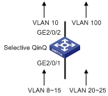
Figure 2-1 Network diagram for selective QinQ configuration
III. Configuration procedure
# Enter system view.
<SwitchA> system-view
[SwitchA]
# Enter GigabitEthernet 2/0/1 port view.
[SwitchA] interface GigabitEthernet 2/0/1
# Configure the port to be a hybrid port.
[SwitchA-GigabitEthernet2/0/1] port link-type hybrid
# Configure the port to permit the packets of all the VLANs.
[SwitchA-GigabitEthernet2/0/1] port hybrid vlan 1 to 4094 tagged
# Set the PVID of the port to 8.
[SwitchA-GigabitEthernet2/0/1] port hybrid pvid vlan 8
# Enable QinQ.
[SwitchA-GigabitEthernet2/0/1] vlan-vpn enable
# Specify the outer VLAN tag to be inserted to packets of VLAN 10, and specify the upstream port of the tag to be GigabitEthernet 2/0/2 which removes the outer VLAN tags of packets when transmitting these packets..
[SwitchA-GigabitEthernet2/0/1] vlan-vpn vid 10 uplink GigabitEthernet 2/0/2 untagged
# Specify the inner VLAN tags. The packets with the specific inner VLAN tags are tagged with the tag of VLAN 10 as the outer VLAN tag.
[SwitchA-GigabitEthernet2/0/1-vid-10] raw-vlan-id inbound 8 to 15
# Specify the outer VLAN tag of VLAN 100 to be inserted to packets, and specify the upstream port of the tag to be GigabitEthernet 2/0/1 which does not remove the outer VLAN tags of packets when transmitting these packets.
[SwitchA-GigabitEthernet2/0/1-vid-10] vlan-vpn vid 100 uplink GigabitEthernet 2/0/2
# Specify the inner VLAN tags. The packets with the specific inner VLAN tags are tagged with the tag of VLAN 100 as the outer VLAN tag.
[SwitchA-GigabitEthernet2/0/1-vid-100] raw-vlan-id inbound 20 to 25
# Return to system view.
[SwitchA-GigabitEthernet2/0/1-vid-100] quit
[SwitchA-GigabitEthernet2/0/1] quit
[SwitchA]
# Enter GigabitEthernet 2/0/2 port view.
[SwitchA] interface GigabitEthernet 2/0/2
[SwitchA-GigabitEthernet2/0/2]
# Configure GigabitEthernet 2/0/1 port as a hybrid port, and then configure the port to remove the outer VLAN tags for the packets with the tag of VLAN 10 as the outer VLAN tags and keep the other outer VLAN tags when packets are forwarded on the port.
[SwitchA-GigabitEthernet2/0/1] port link-type hybrid
[SwitchA-GigabitEthernet2/0/1] port hybrid vlan 1 to 4094 tagged
[SwitchA-GigabitEthernet2/0/1] port hybrid vlan 10 untagged
& Note:
With the configurations above, the packets received on GigabitEthernet 2/0/1 are processed as follows:
l Inserting VLAN 10 tag as the outer VLAN tag to single-tagged packets with their tags being the tags of VLAN 8 through VLAN 15.
l Inserting VLAN 100 tag as the outer VLAN tag to single-tagged packets with their tags being the tags of VLAN 20 through VLAN 25.
l Inserting VLAN 8 tag as the outer VLAN tag to single-tagged packets with their tags being neither the tags of VLAN 8 through VLAN 15 nor the tags of VLAN 20 through VLAN 25.