- Table of Contents
-
- H3C S7500 Series Operation Manual(Release 3100 Series)-(V1.04)
- 00-1Cover
- 00-2Overview
- 01-CLI Configuration
- 02-Login Configuration
- 03-Configuration File Management Configuration
- 04-VLAN Configuration
- 05-Extended VLAN Application Configuration
- 06-IP Address-IP Performance-IPX Configuration
- 07-GVRP Configuration
- 08-QinQ Configuration
- 09-Port Basic Configuration
- 10-Link Aggregation Configuration
- 11-Port Isolation Configuration
- 12-Port Binding Configuration
- 13-DLDP Configuration
- 14-MAC Address Table Configuration
- 15-MSTP Configuration
- 16-Routing Protocol Configuration
- 17-Multicast Configuration
- 18-802.1x Configuration
- 19-AAA-RADIUS-HWTACACS-EAD Configuration
- 20-Traffic Accounting Configuration
- 21-VRRP-HA Configuration
- 22-ARP Configuration
- 23-DHCP Configuration
- 24-ACL Configuration
- 25-QoS Configuration
- 26-Mirroring Configuration
- 27-Cluster Configuration
- 28-PoE Configuration
- 29-UDP-Helper Configuration
- 30-SNMP-RMON Configuration
- 31-NTP Configuration
- 32-SSH Terminal Service Configuration
- 33-File System Management Configuration
- 34-FTP and TFTP Configuration
- 35-Information Center Configuration
- 36-DNS Configuration
- 37-System Maintenance and Debugging Configuration
- 38-HWPing Configuration
- 39-RRPP Configuration
- 40-NAT-Netstream-Policy Routing Configuration
- 41-Telnet Protection Configuration
- 42-Hardware-Dependent Software Configuration
- Related Documents
-
| Title | Size | Download |
|---|---|---|
| 30-SNMP-RMON Configuration | 198 KB |
1.1.1 SNMP Operation Mechanism
1.1.3 MIBs Supported by the Device
1.2 Configuring SNMP Basic Functions
1.3.1 Configuration Prerequisites
1.5 SNMP Configuration Example
1.5.1 SNMP Configuration Example
2.1.1 Working Mechanism of RMON
2.1.2 Commonly Used RMON Groups
2.4 RMON Configuration Example
Chapter 1 SNMP Configuration
When configuring SNMP, go to these sections for information you are interested in:
l Configuring SNMP Basic Functions
1.1 SNMP Overview
By far, the Simple Network Management Protocol (SNMP) has gained the most extensive application in the computer networks. SNMP has been put into use and widely accepted as an industry standard in practice. It is used for ensuring the transmission of the management information between any two nodes in the network. In this way, network administrators can easily retrieve and modify the information on any node in the network. In the meantime, they can locate faults promptly and implement troubleshooting, capacity planning and report generating.
SNMP adopts the polling mechanism and provides the most basic function set. It is most appropriate for small-sized, fast-speed and low-cost environments. SNMP implementation only requires the connectionless transport layer protocol UDP; therefore, SNMP is widely supported by many products.
1.1.1 SNMP Operation Mechanism
SNMP can be divided into two parts, namely, network management station (NMS) and agent:
An NMS is a workstation running client programs. At present, the commonly used NM platforms include QuidView, Sun NetManager and IBM NetView.
Agent is server software running on network devices.
An NMS can send GetRequest, GetNextRequest and SetRequest messages to an agent. Upon receiving a request message from the NMS, the agent will perform Read or Write operation according to the message type, generate and return a Response message to the NMS.
An agent will send Trap messages on its own initiative to the NMS to report events when the device status changes or the device encounters any abnormalities such as restarting the device.
1.1.2 SNMP Versions
Currently an SNMP agent of a device supports SNMPv3, and is compatible with SNMPv1 and SNMPv2c.
SNMPv3 adopts user name and password authentication.
SNMPv1 and SNMPv2c adopt community name authentication. SNMP packets failing to pass community name authentication are discarded. A community name is used to define the relationship between SNMP NMS and SNMP agents. Similar to passwords, a community name can limit access to SNMP agents from the SNMP NMS. You can define the following features relevant to a community name.
l Define a MIB view that a community name can access.
l Assign read-only or read-write access right to MIB objects for the community name. A community name with read-only access right can only query the device information, while a community name with read-write access right can not only query the device information but also configure the device.
l Set the basic ACL specified by the community name.
1.1.3 MIBs Supported by the Device
The management variable in a SNMP packet is used to describe a management object of a device. To uniquely identify a management object of a device in an SNMP packet, SNMP adopts the hierarchical naming scheme to identify managed objects. The hierarchical architecture is like a tree, and each tree node represents a managed object, as shown in Figure 1-1. In this way, an object can be identified through a unique path starting from the root.
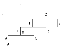
Figure 1-1 Architecture of the MIB tree
The Management Information Base (MIB) is used to describe the hierarchical architecture of the tree and it is the set defined by the standard variables of the monitored network devices. In Figure 1-1, the managed object B can be uniquely identified by a string of numbers {1.2.1.1}. The number string is the object identifier of the managed object B.
Common MIBs supported by the system are listed in Table 1-1.
|
MIB attribute |
MIB content |
References |
|
Public MIB |
MIB II based on TCP/IP network devices |
RFC1213 |
|
BRIDGE MIB |
RFC1493 |
|
|
RFC2675 |
||
|
RIP MIB |
RFC1724 |
|
|
RMON MIB |
RFC2819 |
|
|
Ethernet MIB |
RFC2665 |
|
|
OSPF MIB |
RFC1253 |
|
|
IF MIB |
RFC1573 |
|
|
Private MIB |
DHCP MIB |
— |
|
QACL MIB |
— |
|
|
ADBM MIB |
— |
|
|
RSTP MIB |
— |
|
|
VLAN MIB |
— |
|
|
Device management |
— |
|
|
Interface management |
— |
1.2 Configuring SNMP Basic Functions
The configuration of SNMPv3 is different from that of SNMPv1 and SNMPv2c, so SNMP basic function configurations for different versions are introduced respectively. For specific configurations, refer to the following two tables.
Follow these steps to configure SNMP basic functions for SNMPv1 and SNMPv2c:
|
To do… |
Use the command… |
Remarks |
||
|
Enter system view |
system-view |
— |
||
|
Enable SNMP agent |
snmp-agent |
Optional By default, SNMP agent is disabled To enable SNMP agent, you can execute this command or those commands used to configure SNMP agent features |
||
|
Set system information |
snmp-agent sys-info { contact sys-contact | location sys-location | version { { v1 | v2c | v3 }* | all } } |
Required By default, the contact information for system maintenance is "Hangzhou H3C Technologies Co., Ltd. ", the physical location is "Hangzhou China", and the SNMP version is SNMPv3. |
||
|
Set a community name and access right |
Direct configuration |
Set a community name |
snmp-agent community { read | write } community-name [ acl acl-number | mib-view view-name ]* |
Required l In direct configuration, SNMPv1 and SNMPv2c community names are set directly. l In indirect configuration, SNMPv3 syntax is adopted, and the added user is equal to the community name for SNMPV1 and SNMPV2C. l You can choose either of them as required. |
|
Indirect configuration |
Set an SNMP group |
snmp-agent group { v1 | v2c } group-name [ read-view read-view ] [ write-view write-view ] [ notify-view notify-view ] [ acl acl-number ] |
||
|
Add a new user to an SNMP group |
snmp-agent usm-user { v1 | v2c } user-name group-name [ acl acl-number ] |
|||
|
Set the maximum size of a SNMP packet that the agent can send/receive |
snmp-agent packet max-size byte-count |
Optional By default, it is 2,000 bytes. |
||
|
Set the device engine ID |
snmp-agent local-engineid engineid |
Optional By default, the device engine ID is "enterprise number + device information". |
||
|
Create or update the view information |
snmp-agent mib-view { included | excluded } view-name oid-tree |
Optional By default, the view name is ViewDefault and OID is 1. |
||
Follow these steps to configure SNMP basic functions (SNMPv3):
|
To do… |
Use the command… |
Remarks |
|
Enter system view |
system-view |
— |
|
Enable SNMP agent |
snmp-agent |
Required By default, SNMP agent is disabled. You can enable SNMP agent by executing this command or any configuration command of snmp-agent |
|
Set system information |
snmp-agent sys-info { contact sys-contact | location sys-location | version { { v1 | v2c | v3 }* | all } } |
Optional By default, the contact information for system maintenance is "Hangzhou H3C Technologies Co., Ltd. ", the physical location is "Hangzhou China", and the SNMP version is SNMPv3. |
|
Set an SNMP group |
snmp-agent group v3 group-name [ authentication | privacy ] [ read-view read-view ] [ write-view write-view ] [ notify-view notify-view ] [ acl acl-number ] |
Required |
|
Add a new user to an SNMP group |
snmp-agent usm-user v3 user-name group-name [ authentication-mode { md5 | sha } auth-password [ privacy-mode des56 priv-password ] ] [ acl acl-number ] |
Required |
|
Set the size of a SNMP packet that the agent can send/receive |
snmp-agent packet max-size byte-count |
Optional By default, it is 2,000 bytes. |
|
Set the device engine ID |
snmp-agent local-engineid engineid |
Optional By default, the device engine ID is "enterprise number + device information". |
|
Create or update the view information |
snmp-agent mib-view { included | excluded } view-name oid-tree |
Optional By default, the view name is ViewDefault and OID is 1. |
1.3 Configuring Trap Message
Trap message is the information that the managed device unsolicited sends to the NMS. Trap message is used to report some urgent and important events (e.g., the managed device is rebooted).
1.3.1 Configuration Prerequisites
Complete SNMP basic configuration.
1.3.2 Configuration Procedure
Follow these steps to configure trap message:
1.4 Displaying SNMP
|
To do… |
Use the command… |
Remarks |
|
Display system information of the current SNMP device |
display snmp-agent sys-info [ contact | location | version ]* |
Available in any view |
|
Display statistics on SNMP packets |
display snmp-agent statistics |
|
|
Display the engine ID of the current device |
display snmp-agent { local-engineid | remote-engineid } |
|
|
Display group information about the device |
display snmp-agent group [ group-name ] |
|
|
Display SNMP user information |
display snmp-agent usm-user [ engineid engineid | username user-name | group group-name ] |
|
|
Display the currently configured community name |
display snmp-agent community [ read | write ] |
|
|
Display the currently configured MIB view |
display snmp-agent mib-view [ exclude | include | viewname view-name ] |
1.5 SNMP Configuration Example
1.5.1 SNMP Configuration Example
I. Network requirements
l An NMS and Switch A are connected through the Ethernet. The IP address of the NMS is 10.10.10.1 and that of the VLAN interface on Switch A is 10.10.10.2.
l Perform the following configuration on Switch A: setting the community name and access right, administrator ID, contact and switch location, and enabling the switch to sent trap messages.
II. Network diagram
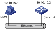
Figure 1-2 Network diagram for SNMP
III. Network procedure
# Set the community name, group name and user.
<H3C> system-view
[H3C] snmp-agent
[H3C] snmp-agent sys-info version all
[H3C] snmp-agent community write public
[H3C] snmp-agent mib-view include internet 1.3.6.1
[H3C] snmp-agent group v3 managev3group write-view internet
[H3C] snmp-agent usm-user v3 managev3user managev3group
# Set VLAN-interface 2 as the interface used by the NMS. Add Ethernet 2/0/2 to VLAN 2. This port will be used for network management. Set the IP address of VLAN-interface 2 as 10.10.10.2.
[H3C] vlan 2
[H3C-vlan2] port Ethernet 2/0/2
[H3C-vlan2] quit
[H3C] interface Vlan-interface 2
[H3C-Vlan-interface2] ip address 10.10.10.2 255.255.255.0
[H3C-Vlan-interface2] quit
# Enable the SNMP agent to send trap messages to the NMS whose IP address is 10.10.10.1. The SNMP community name is public.
[H3C] snmp-agent trap enable standard authentication
[H3C] snmp-agent trap enable standard coldstart
[H3C] snmp-agent trap enable standard linkup
[H3C] snmp-agent trap enable standard linkdown
[H3C] snmp-agent target-host trap address udp-domain 10.10.10.1 udp-port 5000 params securityname public
IV. Configuring NMS
The S7500 series switches support H3C’s QuidView NMS. SNMPv3 adopts user name and password authentication. In [Quidview Authentication Parameter], you need to set a user name, choose security level, and set authorization mode, authorization password, encryption mode, and encryption password respectively according to different security levels. In addition, you must set timeout time and retry times.
You can query and configure Ethernet switches through the NMS. For more information, refer to the manuals of H3C’s NMS products.
& Note:
Authentication configuration on the NMS must be consistent with that on a device; otherwise, the NMS cannot manage the device.
Chapter 2 RMON Configuration
When configuring RMON, go to these sections for information you are interested in:
2.1 RMON Overview
Remote monitoring (RMON) is a kind of Management Information Base (MIB) defined by Internet Engineering Task Force (IETF) and is a most important enhancement made to MIB II standards. RMON is mainly used to monitor the data traffic across a network segment or even the entire network, and is currently a commonly used network management standard.
An RMON system comprises of two parts: the network management station (NMS) and the agents running on network devices. RMON agents operate on network monitors or network probes to collect and keep track of the statistics on the traffic across the network segments to which their ports connect such as the total number of the packets on a network segment in a specific period of time and the total number of packets that are sent to a specific host successfully.
RMON is fully based on Simple Network Management Protocol (SNMP) architecture. It is compatible with the current SNMP, so that you can implement RMON without modifying SNMP. RMON enables SNMP to monitor remote network devices more effectively and actively, thus providing a satisfactory means of monitoring the operation of the subnet. With RMON, the communication traffic between NMS and agents is reduced, thus facilitating the management of large-scale internetworks.
2.1.1 Working Mechanism of RMON
RMON allows multiple monitors. It collects data in one of the following two ways:
l Using the dedicated RMON probe. When an RMON system operates in this way, the NMS directly obtains management information from the RMON probes and controls the network resources. In this case, all information in the RMON MIB can be obtained.
l Embedding RMON agents into network devices (such as routers, switches and hubs) directly to make the latter capable of RMON probe functions. When an RMON system operates in this way, the NMS collects network management information by exchanging information with the SNMP agents using the basic SNMP commands. However, this way depends on device resources heavily and an NMS operating in this way can only obtain information about four groups (instead of all the information in the RMON MIB). The four groups are alarm group, event group, history group and statistics group.
An S7500 switch implements RMON in the second way. With the embedded RMON agent, the S7500 series switch can serve as a network device with the RMON probe function. Through the RMON-capable SNMP agents running on the Ethernet switch, an NMS can obtain the information on the total traffic, error statistics and performance statistics of the network segments to which the ports of the managed network devices are connected. Thus, the NMS can further manage the networks.
2.1.2 Commonly Used RMON Groups
I. Event group
The event group is used to define event indexes and the processing methods for the events. The events defined in an event group are mainly used in alarm group and extended alarm group to trigger alarms.
You can specify a network device to act in one of the following ways in response to an event:
l Logging the event
l Sending trap messages to the NMS
l Logging the event and sending trap messages to the NMS
l No processing
II. Alarm group
RMON alarm management enables monitors on specific alarm variables (such as the statistics of a port). When the value of a monitored variable exceeds the upper threshold or lower threshold, an alarm event is generated, which triggers the network device to act in the set way. Events are defined in event groups.
With an alarm entry defined in an alarm group, a network device performs the following operations accordingly:
l Sampling the defined alarm variables (alarm-variable) once in each specified period (sampling-time)
l Comparing the sampled value with the set threshold and triggering the corresponding events if the sampled value exceeds the threshold
III. Extended alarm group
With extended alarm entries, you can perform operations on the samples of an alarm variable and then compare the operation result with the set threshold, thus implementing more flexible alarm functions.
With an extended alarm entry defined in an extended alarm group, the network devices perform the following operations accordingly:
l Sampling the alarm variables referenced in the defined extended alarm expressions once in each specified period
l Performing operations on sampled values according to the defined operation formulas
l Comparing the operation result with the set threshold and triggering corresponding events if the operation result exceeds the threshold.
IV. History group
After a history group is configured, the Ethernet switch collects network statistics information periodically and stores the statistics information temporarily for later retrieval. A history group can provide the history data of the statistics on network segment traffic, error packets, broadcast packets, and bandwidth utilization.
With the history data management function, you can configure network devices, such as collecting history data, collecting the data of a specific port periodically and saving them.
V. Statistics group
A statistics group contains the statistics of each monitored port on a network device. An entry in a statistics group is an accumulated value counting from the time when the statistics group is created.
The statistics include the number of the following items: collisions, cyclic redundancy check (CRC) error packets, undersized (or oversized) packets, broadcast packets, multicast packets, and received bytes and packets.
With the RMON statistics management function, you can monitor the usage of a port and make statistics on the errors occurring when the ports are being used.
2.2 RMON Configuration
2.2.1 Prerequisites
Before performing RMON configuration, make sure the SNMP agents are correctly configured. For the information about SNMP agent configuration, refer to the “Configuring Basic SNMP Functions” part in SNMP Configuration Operation Manual.
2.2.2 Configuring RMON
|
Use the command… |
Remarks |
|
|
Enter system view |
system-view |
— |
|
Add an event entry |
rmon event event-entry [ description string ] { log | trap trap-community | log-trap log-trapcommunity | none } [ owner text ] |
Optional |
|
Add an alarm entry |
rmon alarm entry-number alarm-variable sampling-time { delta | absolute } rising threshold threshold-value1 event-entry1 falling threshold threshold-value2 event-entry2 [ owner text ] |
Optional Before adding an alarm entry, you need to use the rmon event command to define the event referenced by the alarm entry. |
|
Add an extended alarm entry |
rmon prialarm entry-number prialarm-formula prialarm-des sampling-timer { delta | absolute | changeratio } rising_threshold threshold-value1 event-entry1 falling_threshold threshold-value2 event-entry2 entrytype { forever | cycle cycle-period } [ owner text ] |
Optional Before adding an extended alarm entry, you need to use the rmon event command to define the event referenced by the extended alarm entry. |
|
Enter Ethernet port view |
interface interface-type interface-number |
— |
|
Add a history entry |
rmon history entry-number buckets number interval sampling-interval [ owner text ] |
Optional |
|
Add a statistics entry |
rmon statistics entry-number [ owner text ] |
Optional |
& Note:
l The rmon alarm and rmon prialarm commands take effect on existing nodes only.
l For each port, only one RMON statistics entry can be created. That is, if an RMON statistics entry is already created for a given port, creation of another entry with a different index for the same port will not succeed.
2.3 Displaying RMON
|
To do… |
Use the command… |
Remarks |
|
Display RMON statistics |
display rmon statistics [ interface-type interface-number ] |
Available in any view |
|
Display RMON history information |
display rmon history [ interface-type interface-number ] |
|
|
Display RMON alarm information |
display rmon alarm [ entry-number ] |
|
|
Display extended RMON alarm information |
display rmon prialarm [ prialarm-entry-number ] |
|
|
Display RMON events |
display rmon event [ event-entry ] |
|
|
Display RMON event logs |
display rmon eventlog [ event-entry ] |
2.4 RMON Configuration Example
I. Network requirements
l Ensure that the SNMP agents are correctly configured before performing RMON configuration.
l The switch to be tested has a configuration terminal connected to its console port and is connected to a remote NMS through Internet. Create an entry in the Ethernet statistics table to make statistics on the Ethernet port performance for network administrator’s retrieval.
II. Network diagram
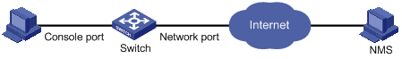
Figure 2-1 Network diagram for RMON configuration
III. Configuration procedures
# Configure RMON.
<H3C> system-view
[H3C] interface Ethernet2/0/1
[H3C-Ethernet2/0/1] rmon statistics 1 owner user1-rmon
# View RMON configuration.
[H3C-Ethernet2/0/1] display rmon statistics Ethernet2/0/1
Statistics entry 1 owned by user1-rmon is VALID.
Interface : Ethernet2/0/1<ifIndex.4227626>
etherStatsOctets : 0 , etherStatsPkts : 0
etherStatsBroadcastPkts : 0 , etherStatsMulticastPkts : 0
etherStatsUndersizePkts : 0 , etherStatsOversizePkts : 0
etherStatsFragments : 0 , etherStatsJabbers : 0
etherStatsCRCAlignErrors : 0 , etherStatsCollisions : 0
etherStatsDropEvents (insufficient resources): 0
Packets received according to length (etherStatsPktsXXXtoYYYOctets):
64 : 0 , 65-127 : 0 , 128-255 : 0
256-511: 0 , 512-1023: 0 , 1024-max: 0