- Table of Contents
-
- H3C S7500 Series Operation Manual(Release 3100 Series)-(V1.04)
- 00-1Cover
- 00-2Overview
- 01-CLI Configuration
- 02-Login Configuration
- 03-Configuration File Management Configuration
- 04-VLAN Configuration
- 05-Extended VLAN Application Configuration
- 06-IP Address-IP Performance-IPX Configuration
- 07-GVRP Configuration
- 08-QinQ Configuration
- 09-Port Basic Configuration
- 10-Link Aggregation Configuration
- 11-Port Isolation Configuration
- 12-Port Binding Configuration
- 13-DLDP Configuration
- 14-MAC Address Table Configuration
- 15-MSTP Configuration
- 16-Routing Protocol Configuration
- 17-Multicast Configuration
- 18-802.1x Configuration
- 19-AAA-RADIUS-HWTACACS-EAD Configuration
- 20-Traffic Accounting Configuration
- 21-VRRP-HA Configuration
- 22-ARP Configuration
- 23-DHCP Configuration
- 24-ACL Configuration
- 25-QoS Configuration
- 26-Mirroring Configuration
- 27-Cluster Configuration
- 28-PoE Configuration
- 29-UDP-Helper Configuration
- 30-SNMP-RMON Configuration
- 31-NTP Configuration
- 32-SSH Terminal Service Configuration
- 33-File System Management Configuration
- 34-FTP and TFTP Configuration
- 35-Information Center Configuration
- 36-DNS Configuration
- 37-System Maintenance and Debugging Configuration
- 38-HWPing Configuration
- 39-RRPP Configuration
- 40-NAT-Netstream-Policy Routing Configuration
- 41-Telnet Protection Configuration
- 42-Hardware-Dependent Software Configuration
- Related Documents
-
| Title | Size | Download |
|---|---|---|
| 13-DLDP Configuration | 151 KB |
Chapter 1 DLDP Configuration
When configuring Device Link Detection Protocol (DLDP), go to these sections for information you are interested in:
l Overview
1.1 Overview
1.1.1 Introduction
You may have encountered unidirectional links in networking. When a unidirectional link occurs, the local device can receive packets from the peer device through the link layer, but the peer device cannot receive packets from the local device. Unidirectional link can cause problems such as Spanning Tree Protocol (STP) loops.
Unidirectional links can be caused by
l Fiber cross-connection, as shown in Figure 1-1
l Fibers that are not connected or disconnected, as shown in Figure 1-2, the hollow lines in which refer to fibers that are not connected or disconnected.
DLDP can detect the link status of an optical fiber cable or copper twisted pair (such as super category 5 twisted pair). If DLDP finds a unidirectional link, it disables the related port automatically or prompts you to disable it manually according to the configurations, to avoid network problems.

Figure 1-1 Fiber cross-connection
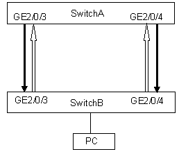
Figure 1-2 Fiber broken or not connected
DLDP provides the following features:
l As a link layer protocol, it works together with the physical layer protocols to monitor the link status of a device.
l The auto-negotiation mechanism at the physical layer detects physical signals and faults. DLDP identifies peer devices and unidirectional links, and disables unreachable ports.
l Even if both ends of links can work normally at the physical layer, DLDP can detect whether these links are connected correctly and whether packets can be exchanged normally at both ends. However, the auto-negotiation mechanism cannot implement this detection.
& Note:
l In order for DLDP to detect fiber disconnection in one direction, you need to configure the port to work in mandatory full duplex mode at a mandatory rate.
l When the port determines the duplex mode and speed through auto-negotiation, even if DLDP is enabled, it does not take effect when the fiber in one direction is disconnected. In this case, the port is considered down.
1.2 DLDP Fundamentals
1.2.1 DLDP Implementation
DLDP detects link status by exchanging the following types of packets.
Table 1-1 DLDP packet types
|
DLDP packet type |
Function |
|
Advertisement |
Notifies the neighbor devices of the existence of the local device. An advertisement packet carries only the local port information, and it does not require response from the peer end. |
|
RSY-Advertisement packets (referred to as RSY packets hereafter) |
Advertisement packet with the RSY flag set to 1. RSY advertisement packets are sent to request synchronizing the neighbor information when neighbor information is not locally available or a neighbor information entry ages out. |
|
Flush-Advertisement packets (referred to as flush packets hereafter) |
Advertisement packet with the flush flag set to 1. A flush packet carries only the local port information (instead of the neighbor information) and is used to trigger neighbors to remove the information about the local device. |
|
Probe |
Probe packets are used to probe the existence of a neighbor. Echo packets are required from the corresponding neighbor. Probe packets carry the local port information. Neighbor information is optional for probe packets. A probe packet carrying neighbor information probes the specified neighbors; A probe packet carrying no neighbor information probes all the neighbors. |
|
Echo |
Response to probe packets. An echo packet carries the information about the response port and the neighbor information it maintains. Upon receiving an echo packet, a port checks whether the neighbor information carried in the echo packet is consistent with that of itself. If yes, the link between the local port and the neighbor is regarded as bidirectional. |
|
Disable |
Disable packets are used to notify the peer end that the local end is in the disable state. Disable packets carry only the local port information instead of the neighbor information. When a port detects a unidirectional link and enters the disable state, the port sends disable packets to the neighbor. A port enters the disable state upon receiving a disable packet. |
|
LinkDown |
Linkdown packets are used to notify unidirectional link emergencies (a unidirectional link emergency occurs when the local port is down and the peer port is up). Linkdown packets carry only the local port information instead of the neighbor information. In some conditions, a port is considered to be physically down if the link connecting to the port is physically abnormal (for example, the Rx line of the fiber on the port is disconnected, while the Tx line operates properly). But for the peer end, as Rx signals can still be received on the physical layer, the port is still considered to be normal. Such a situation is known as unidirectional link emergency. When a unidirectional link emergency occurs, DLDP sends linkdown packets immediately to inform the peer of the link abnormality. Without linkdown packets, the peer can detect the link abnormality only after a period when the corresponding neighbor information maintained on the neighbor device ages out, which is three times the advertisement interval. Upon receiving a linkdown packet, if the peer end operates in the enhanced mode, it enters the disable state, and sets the receiving port to the DLDP down state (auto shutdown mode) or gives an alarm to the user (manual shutdown mode). |
|
Recover Probe |
Recover probe packets are used to detect whether a link recovers to implement the port auto-recovery mechanism. Recover probe packets carry only the local port information instead of the neighbor information. They request for recover echo packets as the response. A port in the DLDP down state sends a recover probe packet every two seconds. |
|
Recover Echo |
Recover echo packets are response to recover probe packets in the port auto-recovery mechanism. A link is considered to restore to the bidirectional state if a port on one end sends a recover probe packet, receives a recover echo packet, and the neighbor information contained in the recover echo packet is consistent with that of the local port. |
1) If the DLDP-enabled link is up, DLDP sends DLDP packets to the peer device, and analyzes/processes the DLDP packets received from the peer device. DLDP packets sent in different DLDP states are of different types.
Table 1-2 DLDP state and DLDP packet type
|
DLDP state |
Type of the DLDP packets sent |
|
Active |
Advertisement packets, with the RSY flag set or not set. |
|
Advertisement |
Advertisement packets |
|
Probe |
Probe packets |
2) A DLDP packet received is processed as follows:
l In authentication mode, the DLDP packet is authenticated and is then dropped if it fails the authentication.
l The packet is further processed, as described in Table 1-3.
Table 1-3 The procedure to process a received DLDP packet
|
Packet type |
Processing procedure |
||||
|
Advertisement packet |
Extracts neighbor information |
If the corresponding neighbor entry does not exist on the local device, DLDP creates the neighbor entry, triggers the entry aging timer, and switches to the probe state. |
|||
|
If the corresponding neighbor entry already exists on the local device, DLDP resets the aging timer of the entry. |
|||||
|
Flush packet |
Removes the neighbor entry from the local device |
||||
|
Probe packet |
Sends echo packets containing both neighbor and its own information to the peer |
Creates the neighbor entry if it does not exist on the local device. |
|||
|
Resets the aging timer of the entry if the neighbor entry already exists on the local device. |
|||||
|
Echo packet |
Checks to see if the local device is in the probe state |
No |
Drops the echo packet |
||
|
Yes |
Checks to see if the neighbor information contained in the packet is the same as that on the local device |
No |
Drops the echo packet |
||
|
Yes |
Sets the flag bit of the neighbor to bidirectional link |
||||
|
If all neighbors are in the bidirectional link state, DLDP switches from the probe state to the advertisement state, and sets the echo waiting timer to 0. |
|||||
3) If no echo packet is received from the neighbor, DLDP performs the following processing:
Table 1-4 Processing procedure when no echo packet is received from the neighbor
|
No echo packet received from the neighbor |
Processing procedure |
|
In normal mode, no echo packet is received when the echo waiting timer expires. |
DLDP switches to the disable state, outputs log and tracking information, and sends flush packets. Depending on the user-defined DLDP down mode, DLDP disables the local port automatically or prompts you to disable the port manually. DLDP sends RSY messages and removes the corresponding neighbor entries. |
|
In enhanced mode, no echo packet is received when the enhanced timer expires |
1.2.2 DLDP Status
A link can be in one of these DLDP states: initial, inactive, active, advertisement, probe, disable, and delaydown.
|
Status |
Description |
|
Initial |
Initial status before DLDP is enabled. |
|
Inactive |
DLDP is enabled but the corresponding link is down |
|
Active |
DLDP is enabled, and the link is up or an neighbor entry is cleared |
|
Advertisement |
All neighbors communicate normally in both directions, or DLDP remains in active state for more than five seconds and enters this status. It is a stable state where no unidirectional link is found |
|
Probe |
DHCP sends packets to check whether the link is a unidirectional. It enables the probe sending timer and an echo waiting timer for each target neighbor. |
|
Disable |
DLDP detects a unidirectional link, or finds (in enhanced mode) that a neighbor disappears. In this case, DLDP sends and receives only recover probe packets and recover echo packets. |
|
DelayDown |
When a device in the active, advertisement, or probe DLDP state receives a port down message, it does not removes the corresponding neighbor immediately, neither does it changes to the inactive state. Instead, it changes to the delaydown state first. When a device changes to the delaydown state, the related DLDP neighbor information remains, and the DelayDown timer is triggered. After the DelayDown timer expires, the DLDP neighbor information is removed. |
1.2.3 DLDP Timers
|
Timer |
Description |
|
Advertisement sending timer |
Interval between sending advertisement packets, which can be configured on a command line interface. By default, the timer length is 5 seconds. |
|
Probe sending timer |
The interval is 0.5 seconds. In the probe state, DLDP sends two probe packets in a second. |
|
Echo waiting timer |
It is enabled when DLDP enters the probe state. The echo waiting timer length is 10 seconds. If no echo packet is received from the neighbor when the Echo waiting timer expires, the state of the local end is set to unidirectional link (one-way audio) and the state machine turns into the disable state. DLDP outputs log and tracking information, sends flush packets. Depending on the user-defined DLDP down mode, DLDP disables the local port automatically or prompts you to disable the port manually. At the same time, DLDP deletes the neighbor entry. |
|
Entry aging timer |
When a new neighbor joins, a neighbor entry is created and the corresponding entry aging timer is enabled When an advertisement packet is received from a neighbor, the neighbor entry is updated and the corresponding entry aging timer is updated In the normal mode, if no packet is received from the neighbor when the entry aging timer expires, DLDP sends an advertisement packet with an RSY tag, and deletes the neighbor entry. In the enhanced mode, if no packet is received from the neighbor when the entry aging timer expires, DLDP enables the enhanced timer The entry aging timer length is three times the advertisement timer length. |
|
Enhanced timer |
In the enhanced mode, if no packet is received from the neighbor when the entry aging timer expires, DLDP enables the enhanced timer for the neighbor. The enhanced timer length is 10 seconds The enhanced timer then sends one probe packet every second and eight packets successively to the neighbor. If no echo packet is received from the neighbor when the enhanced timer expires, the state of the local end is set to unidirectional communication state and the state machine turns into the disable state. DLDP outputs log and tracking information and sends flush packets. Depending on the user-defined DLDP down mode, DLDP disables the local port automatically or prompts you to disable the port manually. Meanwhile, DLDP deletes the neighbor entry. |
|
DelayDown timer |
When a device in the active, advertisement, or probe DLDP state receives a port down message, it does not removes the corresponding neighbor immediately, neither does it changes to the inactive state. Instead, it changes to the delaydown state first. When a device changes to the delaydown state, the related DLDP neighbor information remains, and the DelayDown timer is triggered. The DelayDown timer is configurable and ranges from 1 to 5 seconds. A device in the delaydown state only responds to port up messages. A device in the delaydown state resumes its original DLDP state if it receives a port up message before the delaydown timer expires. Otherwise, it removes the DLDP neighbor information and changes to the inactive state. |
1.2.4 DLDP Operating Mode
DLDP can operate in two modes: normal and enhanced.
Table 1-7 DLDP operating mode and neighbor entry aging
|
DLDP operating mode |
DLDP detects whether neighbors exist or not when neighbor tables are aging |
The entry aging timer is enabled or not during neighbor entry aging |
The enhanced timer is enabled or not when the entry aging timer expires |
|
Normal mode |
No |
Yes (The neighbor entry ages out after the entry aging timer expires) |
No |
|
Enhanced mode |
Yes |
Yes (The enhanced timer is enabled after the entry aging timer expires) |
Yes (When the enhanced timer expires, the state of the local end is set to unidirectional link, and the neighbor entry is aged out.) |
1.2.5 DLDP Neighbor State
A DLDP neighbor can be in one of these two states: two way and unknown. You can check the state of a DLDP neighbor by using the display dldp command.
Table 1-8 Description on the two DLDP neighbor states
|
DLDP neighbor state |
Description |
|
two way |
The link to the neighbor operates properly. |
|
unknown |
The device is detecting the neighbor and the neighbor state is unknown. |
1.2.6 Link Auto-recovery Mechanism
If the shutdown mode of a port is set to auto shutdown, the port is set to the DLDP down state when DLDP detects the link connecting to the port is a unidirectional link. A port in DLDP down state does not forward service packets or receive/send protocol packets except DLDPDUs.
A port in the DLDP down state recovers when the corresponding link recovers. A port in the DLDP down state sends recover probe packets periodically. On receiving a correct recover echo packet (which means that the unidirectional link is restored to a bidirectional link), it is brought up by DLDP. The detailed process is as follows.
1) A port in the DLDP down state sends a recover probe packet every 2 seconds. Recover probe packets carry only the local port information.
2) Upon receiving a recover probe packet, the peer end responds with a recover echo packet.
3) Upon receiving a recover echo packet, the local end checks to see if the neighbor information carried in the recover echo packet is consistent with that of the local port. If yes, the link between the local port and the neighbor is considered to be recovered to bidirectional, the port changes from the disable state to the active state, and neighboring relationship is reestablished between the local port and the neighbor.
& Note:
Only ports in the DLDP down state can send and process recover probe packets and recover echo packets. The auto-recovery mechanism does apply to ports that are shut down manually.
1.3 DLDP Configuration
1.3.1 Configuring DLDP
& Note:
For a port with DLDP enabled, you are not recommended to execute the port monitor last command on the port. If it is necessary, the value argument in this command must be less than 10.
Follow these steps to configure DLDP:
|
Use the command… |
Remarks |
|||
|
Enter system view |
system-view |
— |
||
|
Enable DLDP |
Enable DLDP globally |
dldp enable |
Required. Enable DLDP globally and then enable DLDP on the specified port. |
|
|
Enable DLDP on a port |
Enter Ethernet port view |
interface interface-type interface-number |
||
|
Enable DLDP on a port |
dldp enable |
|||
|
Set the authentication mode and password |
dldp authentication-mode { none | simple simple-password | md5 md5-password } |
Optional By default, the authentication mode is none, that is, authentication is not performed. |
||
|
Set the interval of sending DLDP packets |
dldp interval value |
Optional. By default, the interval of sending DLDP packets is 5 seconds. |
||
|
Set the delaydown timer |
dldp delaydown-timer delaydown-time |
Optional By default, the delaydown timer expires after 1 second it is triggered. |
||
|
Set the DLDP handling mode when an unidirectional link is detected |
dldp unidirectional-shutdown { auto | manual } |
Optional By default, the handling mode is auto |
||
|
Set the operating mode of DLDP |
dldp work-mode { enhance | normal } |
Optional By default, DLDP works in normal mode. |
||
|
Enter Ethernet port view |
interface interface-type interface-number |
— |
||
|
Force the duplex attribute |
duplex full |
Required If you want to use DLDP to detect which fiber of the two fibers is not connected or fails, you must configure the ports to work in the mandatory full duplex mode. |
||
|
Force the speed value |
speed speed-value |
Required |
||
|
Display the configuration information about the DLDP-enabled ports |
display dldp [ interface-type interface-number ] |
— |
||
& Note:
l When you use the dldp enable/dldp disable command in system view to enable/disable DLDP globally on all optical ports of the switch, this command is only valid for existing optical ports on the device, however, it is not valid for those added subsequently.
l DLDP can operate normally only when the same authentication mode and password are set for local and peer ports.
l When the DLDP protocol works in normal mode, the system can identify only one type of unidirectional links: cross-connected fibers.
l When the DLDP protocol works in enhanced mode, the system can identify two types of unidirectional links: the first type is the cross-connected fiber, and the second type is one of the two fibers is not connected or fails.
l When the device is busy with services and the CPU utilization is high, DLDP may issue mistaken reports. You are recommended to configure the operating mode of DLDP as manual after unidirectional links are discovered.
l For the dldp interval integer command, make sure that the same interval for transmitting advertisement packets is set on the ports used to connected both devices; otherwise DLDP will not operate properly.
1.3.2 Resetting DLDP Status
& Note:
Only after the ports are DLDP down due to the detection of unidirectional links can you use the dldp reset command to reset the DLDP status of these ports to retrieve DLDP probes.
Follow these steps to reset DLDP status:
|
Use the command… |
Remarks |
||
|
Enter system view |
system-view |
— |
|
|
Reset the status of DLDP globally |
dldp reset |
Optional |
|
|
Reset the status of DLDP on a port |
Enter Ethernet port view |
interface interface-type interface-number |
— |
|
Reset the status of DLDP on 100 M Ethernet ports |
dldp reset |
Optional |
|
|
Reset the status of DLDP on Gigabit Ethernet ports |
dldp reset |
||
![]() Caution:
Caution:
l This command only applies to the ports in DLDP down status.
l If a port is DLDP down, it can return to the up state automatically. You do not need to reset DLDP on the port.
1.3.3 Precautions During DLDP Configuration
l DLDP does not work on a port where you configure duplex and rate forcibly, such as 10 GE port.
l DLDP works only when the link is up.
l To insure that DLDP neighbors can be established properly and unidirectional links can be detected, you must make sure: DLDP is enabled on both ends, and the interval of sending DLDP advertisement packets, authentication mode and password are consistent on both ends.
l You can adjust the interval of sending DLDP advertisement packets (which is 5 seconds by default and in the range of 1 seconds to 100 seconds) in different network circumstances, so that DLDP can respond rapidly to link failure. The interval must be shorter than one-third of the STP convergence time, which is generally 30 seconds. If too long an interval is set, an STP loop may occur before DLDP shut down unidirectional links. On the contrary, if too short an interval is set, network traffic increases, and port bandwidth is reduced.
l DLDP is also applicable to STP Discarding ports. Ports discarded by STP can set up normal DLDP neighbors and detect unidirectional links.
l DLDP does not process any LACP event, and treats each link in the aggregation group as independent.
l The mandatory duplex mode must be enabled on both ends of the DLDP link. In this way, unidirectional links will be reported and the ports can be shut down as required; if the auto-negotiation duplex mode is configured on both ends, unidirectional links will not be reported and ports will not be shut down, while only the state of DLDP neighbors changes.
l If DLDP is enabled after unidirectional links appear, DLDP cannot detect unidirectional links.
l DLDP cannot be used together with similar protocols of other companies, that is, you cannot enable DLDP on one end and enable one of the similar protocols of other companies.
For XGbus products, pay attention to the following points:
l When interface boards are hot swapped, if the plugged interface board is of the same type as the pulled interface board, DLDP restores automatically.
l When active/standby switchover is performed on an SRPU, the standby SRPU detects unidirectional links instead of the SRPU. DLDP parameters remain the same and unidirectional links are detected again on each port.
1.4 DLDP Network Example
I. Network requirements
As shown in Figure 1-3:
l Switch A and Switch B are connected through two pairs of fibers. Both of them support DLDP;
l Suppose the fibers between Switch A and Switch B are cross-connected. DLDP disconnects the unidirectional links after detecting them;
l When the network administrator connects the fiber correctly, the ports taken down by DLDP are restored.
II. Network diagram
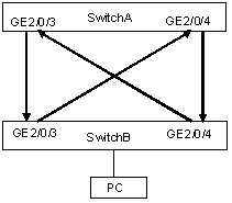
Figure 1-3 Fiber cross-connection
III. Configuration procedure
1) Configure Switch A
# Configure the ports to work in mandatory full duplex mode at the speed of 1000 Mbps.
<H3CA> system-view
[H3CA] interface gigabitethernet 2/0/3
[H3CA-GigabitEthernet2/0/3] duplex full
[H3CA-GigabitEthernet2/0/3] speed 1000
[H3CA-GigabitEthernet2/0/3] quit
[H3CA] interface gigabitethernet 2/0/4
[H3CA-GigabitEthernet2/0/4] duplex full
[H3CA-GigabitEthernet2/0/4] speed 1000
[H3CA-GigabitEthernet2/0/4] quit
# Enable DLDP globally
[H3CA] dldp enable
# Set the interval of sending DLDP packets to 15 seconds
[H3CA] dldp interval 15
# Configure DLDP to work in enhanced mode
[H3CA] dldp work-mode enhance
# Set the DLDP handling mode to auto after unidirectional links are detected
[H3CA] dldp unidirectional-shutdown auto
# Display the DLDP status
[H3CA] display dldp
& Note:
If the fibers are correctly connected between the two switches, the system displays the connections with the neighbor as bidirectional links.
When the fibers are not correctly connected:
l When the fibers are cross-connected, both ends are unidirectional links and the two ends are displayed as in Disable status;
l When one end is correctly connected and the other end is not connected, one end is in Advertisement status and the other is in Inactive status.
# Restore the ports taken down by DLDP
[H3CA] dldp reset
2) Configure Switch B
The configuration of Switch B is the same to that of Switch A.
& Note:
Suppose the port works in the mandatory full duplex mode and the connection at both ends of the link is normal. After DLDP is enabled, if the optical fiber in one end is not connected, DLDP will report that the link is a unidirectional link.