- Table of Contents
-
- H3C S7500 Series Operation Manual(Release 3100 Series)-(V1.04)
- 00-1Cover
- 00-2Overview
- 01-CLI Configuration
- 02-Login Configuration
- 03-Configuration File Management Configuration
- 04-VLAN Configuration
- 05-Extended VLAN Application Configuration
- 06-IP Address-IP Performance-IPX Configuration
- 07-GVRP Configuration
- 08-QinQ Configuration
- 09-Port Basic Configuration
- 10-Link Aggregation Configuration
- 11-Port Isolation Configuration
- 12-Port Binding Configuration
- 13-DLDP Configuration
- 14-MAC Address Table Configuration
- 15-MSTP Configuration
- 16-Routing Protocol Configuration
- 17-Multicast Configuration
- 18-802.1x Configuration
- 19-AAA-RADIUS-HWTACACS-EAD Configuration
- 20-Traffic Accounting Configuration
- 21-VRRP-HA Configuration
- 22-ARP Configuration
- 23-DHCP Configuration
- 24-ACL Configuration
- 25-QoS Configuration
- 26-Mirroring Configuration
- 27-Cluster Configuration
- 28-PoE Configuration
- 29-UDP-Helper Configuration
- 30-SNMP-RMON Configuration
- 31-NTP Configuration
- 32-SSH Terminal Service Configuration
- 33-File System Management Configuration
- 34-FTP and TFTP Configuration
- 35-Information Center Configuration
- 36-DNS Configuration
- 37-System Maintenance and Debugging Configuration
- 38-HWPing Configuration
- 39-RRPP Configuration
- 40-NAT-Netstream-Policy Routing Configuration
- 41-Telnet Protection Configuration
- 42-Hardware-Dependent Software Configuration
- Related Documents
-
| Title | Size | Download |
|---|---|---|
| 17-Multicast Configuration | 1 MB |
1.1.1 Information Transmission in the Unicast Mode
1.1.2 Information Transmission in the Broadcast Mode
1.1.3 Information Transmission in the Multicast Mode
1.1.4 Advantages and Applications of Multicast
1.3 Forwarding Mechanism of Multicast Packets
2.2.2 Enabling GMRP on the Port
2.3 Displaying and Maintaining GMRP
2.4 GMRP Configuration Example
Chapter 3 IGMP Snooping Configuration
3.1.1 IGMP Snooping Fundamentals
3.1.2 IGMP Snooping Implementation
3.2 IGMP Snooping Configuration
3.2.3 Enabling IGMP Fast Leave
3.2.4 Configuring IGMP Snooping Filtering ACLs
3.2.5 Configuring to Limit the Number of Multicast Groups on a Port
3.2.6 Configuring Suppression on IGMP Report Messages
3.2.7 Configuring Multicast VLAN
3.3 Displaying and Maintaining IGMP Snooping
3.4 IGMP Snooping Configuration Examples
3.5 Troubleshooting IGMP Snooping
Chapter 4 Common Multicast Configuration
4.2 Common Multicast Configuration
4.2.1 Enabling Multicast and Configuring Limit on the Number of Route Entries
4.2.2 Configuring Suppression on the Multicast Source Port
4.2.3 Configuring Suppression on Multicast Wrongif Packets
4.2.4 Configuring Static Router Ports
4.2.5 Clearing Multicast Related Entries
4.3 Displaying and Maintaining Common Multicast Configuration
Chapter 5 Multicast MAC Address Entry Configuration
5.2 Configuring a Multicast MAC Address Entry
5.3 Displaying and Maintaining Multicast MAC Address
6.1.3 Working Procedure of IGMP
6.2.1 Configuring IGMP Version
6.2.2 Configuring IGMP Query Messages
6.2.3 Configuring IGMP Multicast Groups on the Interface
6.2.4 Configuring Router Ports to Join the Specified Multicast Group
6.2.6 Configuring Suppression on IGMP Report Messages
6.2.7 Removing the Joined IGMP Groups from the Interface
6.3 Displaying and Maintaining IGMP
7.1.2 Work Mechanism of PIM-DM
7.1.4 Work Mechanism of PIM-SM
7.2.1 Enabling PIM-DM (PIM-SM) on the Interface
7.2.2 Configuring the Interval of Sending Hello Messages
7.2.3 Configuring PIM Neighbors
7.2.4 Clearing PIM Relevant Entries
7.3.1 Configuring Filtering Policies for Multicast Source/Group
7.4.1 Configuring Filtering Policies for Multicast Source/Group
7.4.3 Configuring PIM-SM Domain Boundary
7.4.4 Configuring the RP to Filter Register Messages from the DR
7.5 Displaying and Maintaining PIM
7.6 PIM Configuration Examples
7.6.1 PIM-DM Configuration Example
7.6.2 PIM-SM Configuration Example
Chapter 1 Multicast Overview
1.1 Multicast Overview
With development of networks on the Internet, more and more interaction services such as data, voice, and video services are running on the networks. In addition, services highly dependent on bandwidth and real-time data interaction, such as e-commerce, web conference, online auction, video on demand (VoD), and tele-education have come into being. These services have higher requirements for information security, legal use of paid services, and network bandwidth.
1.1.1 Information Transmission in the Unicast Mode
In unicast, the system establishes a separate data transmission channel for each user requiring this information, and sends separate copy information to the user, as shown in Figure 1-1:
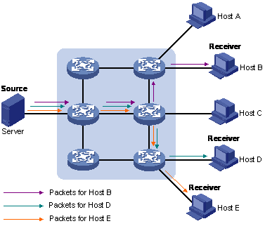
Figure 1-1 Information transmission in the unicast mode
Assume that users B, D and E need this information. The source server establishes transmission channels for the devices of these users respectively. As the transmitted traffic over the network is proportional to the number of users that receive this information, when a large number of users need this information, the server must send many pieces of information with the same content to the users. Therefore, the limited bandwidth becomes the bottleneck in information transmission. This shows that unicast is not good for the transmission of a great deal of information.
1.1.2 Information Transmission in the Broadcast Mode
When you adopt broadcast, the system transmits information to all users on a network. Any user on the network can receive the information, no matter the information is needed or not. Figure 1-2 shows information transmission in broadcast mode.
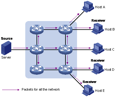
Figure 1-2 Information transmission in the broadcast mode
Assume that users B, D, and E need the information. The source server broadcasts this information through routers, and users A and C on the network also receive this information. The security and payment of the information cannot be guaranteed.
As we can see from the information transmission process, the security and legal use of paid service cannot be guaranteed. In addition, when only a small number of users on the same network need the information, the utilization ratio of the network resources is very low and the bandwidth resources are greatly wasted.
1.1.3 Information Transmission in the Multicast Mode
As described in the previous sections, unicast is suitable for networks with sparsely distributed users, whereas broadcast is suitable for networks with densely distributed users. When the number of users requiring information is not certain, unicast and broadcast are both of low efficiency.
Multicast solves this problem. When some users on a network require specified information, the multicast information sender (namely, the multicast source) sends the information only once. With tree-type routes established for multicast data packets through a multicast routing protocol, the packets are duplicated and distributed at the nearest nodes to the destination as shown in Figure 1-3:

Figure 1-3 Information transmission in the multicast mode
Assume that users B, D and E need the information. To transmit the information to the right users, it is necessary to group users B, D and E into a receiver set. The routers on the network duplicate and distribute the information based on the distribution of the receivers in this set. Finally, the information is correctly delivered to users B, D, and E.
The advantages of multicast over unicast are as follows:
l No matter how many receivers exist, there is only one copy of the same multicast data flow on each link.
l With the multicast mode used to transmit information, an increase in the number of users does not add to the network load significantly.
The advantages of multicast over broadcast are as follows:
l A multicast data flow can be sent only to the receiver that requires the data.
l Multicast brings no waste of network resources and makes proper use of bandwidth.
In the multicast mode, network components can be divided in to the following roles:
l An information sender is referred to as a multicast source.
l Multiple receivers receiving the same information form a multicast group. Multicast group is not limited by physical area.
l Each receiver receiving multicast information is a multicast group member.
l A router providing multicast routing is a multicast router. The multicast router can be a member of one or multiple multicast groups, and it can also manage members of the multicast groups.
For a better understanding of the multicast concepts, you can assimilate a multicast group to a TV channel. A TV station is a multicast source. It sends data to the channel. The audience are the receivers. After turning on a TV set (a computer), they can select a channel to receive a program (namely join in a group) and then watch the program. Therefore, a multicast group should be an agreement between the sender and the receivers, like the frequency of a channel.
![]() Caution:
Caution:
A multicast source does not necessarily belong to a multicast group. A multicast source sends data to a multicast group, and it is not necessarily a receiver. Multiple multicast sources can send packets to the same multicast group at the same time.
1.1.4 Advantages and Applications of Multicast
I. Advantages of multicast
Advantages of multicast include:
l Enhanced efficiency: Multicast decreases network traffic and reduces server load and CPU load.
l Optimal performance: Multicast reduces redundant traffic.
l Distributive application: Multicast makes multiple-point application possible.
II. Application of multicast
The multicast technology effectively addresses the issue of point-to-multipoint data transmission. By enabling high-efficiency point-to-multipoint data transmission, over an IP network, multicast greatly saves network bandwidth and reduces network load.
Multicast provides the following applications:
l Applications of multimedia and flow media, such as Web TV, Web radio, and real-time video/audio conferencing.
l Communication for training and cooperative operations, such as remote education.
l Database and financial applications (stock), and so on.
l Any point-to-multiple-point data application.
1.2 Multicast Architecture
IP multicast is designed to transmit information from a multicast source to receivers in the multicast mode and to satisfy information requirements of receivers. You should be concerned about:
l Host registration: What receivers reside on the network?
l Multicast source discovery: Which multicast source should the receivers receive information from?
l Multicast addressing mechanism: Where should the multicast source transmit information to?
l Multicast routing: How is information transmitted?
IP multicast is a kind of peer-to-peer service. Based on the protocol layer sequence from bottom to top, the multicast mechanism contains addressing mechanism, host registration, multicast routing, and multicast application.
l Addressing mechanism: Information is sent from a multicast source to a group of receivers through multicast addresses.
l Host registration: A receiving host joins and leaves a multicast group dynamically to implement multicast membership registration.
l Multicast routing: A router or switch establishes a packet distribution tree and transmits packets from a multicast source to receivers.
1.2.1 Multicast Address
As receivers are multiple hosts in a multicast group, you should be concerned about the following questions:
l What destination should the information source send the information to in the multicast mode?
l How to select the destination address, that is, how does the information source know who the user is?
These questions are about multicast addressing. To enable the communication between the information source and members of a multicast group (a group of information receivers), network-layer multicast addresses, namely, IP multicast addresses are required. In addition, a technology must be available to map IP multicast addresses to link-layer MAC multicast addresses. The following sections describe these two types of multicast addresses:
I. IP multicast address
Internet Assigned Numbers Authority (IANA) categorizes IP addresses into five classes: A, B, C, D, and E. Unicast packets use IP addresses of Class A, B, and C based on network scales. Class D IP addresses are used as destination addresses of multicast packets. Class D addresses must not appear in the source IP address field of an IP packets. Class E IP addresses are reserved for future use.
In unicast data transmission, a data packet is transmitted hop by hop from the source address to the destination address. In an IP multicast environment, the destination address of a packet is a multicast group address identifying a multicast group. All the receivers join a group. Once they join the group, the data sent to this group of addresses starts to be transmitted to the receivers. All the members in this group can receive the data packets. This group is a multicast group.
A multicast group has the following characteristics:
l The membership of a group is dynamic. A host can join and leave a multicast group at any time.
l A multicast group can be either permanent or temporary.
l A multicast group whose addresses are assigned by IANA is a permanent multicast group. It is also called reserved multicast group.
Note that:
l The IP address of a permanent multicast group keeps unchanged, while the members of the group can be changed.
l There can be any number of, or even zero, members in a permanent multicast group.
l Those IP multicast addresses not assigned to permanent multicast groups can be used by temporary multicast groups.
Class D IP addresses range from 224.0.0.0 to 239.255.255.255. For details, see Table 1-1.
Table 1-1 Range and description of Class D IP addresses
|
Description |
|
|
224.0.0.0 to 224.0.0.255 |
Reserved multicast addresses (IP addresses for permanent multicast groups). The IP address 224.0.0.0 is reserved. Other IP addresses can be used by routing protocols. |
|
224.0.1.0 to 231.255.255.255 233.0.0.0 to 238.255.255.255 |
Available any-source multicast (ASM) multicast addresses (IP addresses of temporary groups). They are valid for the entire network. |
|
232.0.0.0 to 232.255.255.255 |
Available source-specific multicast (SSM) multicast group addresses. |
|
239.0.0.0 to 239.255.255.255 |
Local management multicast addresses, which are available in the specific local scope only. |
As specified by IANA, the IP addresses ranging from 224.0.0.0 to 224.0.0.255 are reserved for routing protocols on local networks. The following table lists commonly used reserved IP multicast addresses:
Table 1-2 Reserved IP multicast addresses
|
Class D address range |
Description |
|
224.0.0.1 |
Address of all hosts |
|
224.0.0.2 |
Address of all multicast routers |
|
224.0.0.3 |
Unassigned |
|
224.0.0.4 |
Distance vector multicast routing protocol (DVMRP) routers |
|
224.0.0.5 |
Open shortest path first (OSPF) routers |
|
224.0.0.6 |
Open shortest path first designated routers (OSPF DR) |
|
224.0.0.7 |
Shared tree routers |
|
224.0.0.8 |
Shared tree hosts |
|
224.0.0.9 |
RIP-2 routers |
|
224.0.0.11 |
Mobile agents |
|
224.0.0.12 |
DHCP server / relay agent |
|
224.0.0.13 |
All protocol independent multicast (PIM) routers |
|
224.0.0.14 |
Resource reservation protocol (RSVP) encapsulation |
|
224.0.0.15 |
All core-based tree (CBT) routers |
|
224.0.0.16 |
The specified subnetwork bandwidth management (SBM) |
|
224.0.0.17 |
All SBMS |
|
224.0.0.18 |
Virtual router redundancy protocol (VRRP) |
|
224.0.0.19– 224.0.0.255 |
Other protocols |
& Note:
Like having reserved the private network segment 10.0.0.0/8 for unicast, IANA has also reserved the network segments ranging from 239.0.0.0 to 239.255.255.255 for multicast. These are administratively scoped addresses. With the administratively scoped addresses, you can define the range of multicast domains flexibly to isolate IP addresses between different multicast domains, so that the same multicast address can be used in different multicast domains without causing collisions.
II. Ethernet multicast MAC address
When a unicast IP packet is transmitted in an Ethernet network, the destination MAC address is the MAC address of the receiver. When a multicast packet is transmitted in an Ethernet network, a multicast MAC address is used as the destination address because the destination is a group with an uncertain number of members.
As stipulated by IANA, the high-order 24 bits of a multicast MAC address are 0x01005e, while the low-order 23 bits of a MAC address are the low-order 23 bits of the multicast IP address. Figure 1-4 describes the mapping relationship:
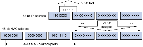
Figure 1-4 Mapping relationship between multicast IP address and multicast MAC address
The high-order four bits of the IP multicast address are 1110, representing the multicast ID. Only 23 bits of the low-order 28 bits are mapped to a MAC address Thus five bits of the multicast IP address are lost. As a result, 32 IP multicast addresses are mapped to the same MAC address.
1.2.2 IP Multicast Protocols
IP multicast protocols include multicast group management protocols and multicast routing protocols. Figure 1-5 describes the positions of multicast-relevant protocols in the network.
Figure 1-5 Positions of multicast-relevant protocols
I. Multicast group management protocol
Internet group management protocol (IGMP) runs between hosts and multicast routers. This protocol defines the mechanism of establishing and maintaining group membership between hosts and routers.
II. Multicast routing protocols
A multicast routing protocol operates between multicast routers to establish and maintain multicast routes and forward multicast packets accurately and effectively. A multicast route establishes a loop-free data transmission path from a data source to multiple receivers. The multicast routing protocol is designed to establish a distribution tree. Multicast routers can establish the data transmission path (namely, distribution tree) in many ways.
Like unicast routes, multicast routes come in intra-domain routes and inter-domain routes. Intra-domain multicast routes are quite mature now. Protocol independent multicast (PIM) is the most commonly used protocol currently. It can cooperate with any unicast routing protocol.
1.3 Forwarding Mechanism of Multicast Packets
In a multicast model, a multicast source transmits information to the multicast group, which is identified by the multicast group address in the destination address field of an IP data packet. Unlike a unicast model, a multicast model must forward data packets to multiple external interfaces so that all receivers can receive the packets. Therefore the forwarding process of multicast is more complicated than unicast.
Based on the source address, a multicast router judges whether a multicast packet comes from the specified interface, that is, RPF check determines whether the inbound interface is correct by comparing the interface receiving the packet with the interface that must receive the packet. If the router resides on a shortest path tree (SPT), the interface that must receive the multicast packet points to the multicast source. If the router resides on a rendezvous point tree (RPT), the interface that must receive the multicast packet points to the rendezvous point (RP). When a multicast data packet reaches the router, if RPF check passes, the router forwards the data packet based on its multicast forwarding entry; otherwise, the data packet is dropped.
Chapter 2 GMRP Configuration
2.1 GMRP Overview
GMRP (GARP Multicast Registration Protocol), based on GARP, is used for maintaining multicast registration information of the switch. All GMRP-capable switches can receive multicast registration information from other switches, dynamically update local multicast registration information, and send their own local multicast registration information to other switches. This information switching mechanism keeps consistency of the multicast information maintained by every GMRP-supporting device in the same switching network.
A host sends a GMRP Join message, if it is interested in joining a multicast group. After receiving the message, the switch adds the port on which the message was received to the multicast group, and broadcasts the message throughout the VLAN where the receiving port resides. In this way, the multicast source in the VLAN gets aware of the existence of the multicast group member. When the multicast source sends multicast packets to a group, the switch only forwards the packets to ports connected to the members of that group, thereby implementing Layer 2 multicast in the VLAN.
2.2 Configuring GMRP
The main tasks in GMRP configuration include:
l Enable GMRP globally
l Enable GMRP on a port
GMRP must be enabled globally before it is enabled on a port.
2.2.1 Enabling GMRP Globally
Follow these steps to enable GMRP globally:
|
To do... |
Use the command... |
Remarks |
|
Enter system view |
system-view |
— |
|
Enable GMRP globally. |
gmrp |
Required Disabled by default. |
2.2.2 Enabling GMRP on the Port
Perform the following configuration to enable/disable GMRP on the port in Ethernet port view:
|
To do... |
Use the command... |
Remarks |
|
Enter system view |
system-view |
— |
|
Enter Ethernet port view |
interface interface-type interface-number |
— |
|
Enable GMRP on the port |
gmrp |
Required Disabled by default. |
2.3 Displaying and Maintaining GMRP
|
To do... |
Use the command... |
Remarks |
|
Display the GMRP statistics information |
display gmrp statistics [ interface interface-list ] |
Available in any view |
|
Display the GMRP global status |
display gmrp status |
2.4 GMRP Configuration Example
2.4.1 Enabling GMRP
I. Network requirements
Implement dynamic registration and update of multicast information between switches.
II. Network diagram
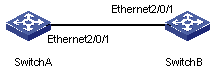
Figure 2-1 Networking diagram for GMRP configuration
III. Configuration procedure
# Enable GMRP globally.
<H3C> system-view
[H3C] gmrp
GMRP is enabled globally.
# Enable GMRP on the port.
[H3C] interface Ethernet2/0/1
[H3C-Ethernet2/0/1] gmrp
GMRP is enabled on port Ethernet2/0/1.
Configure SwitchB:
# Enable GMRP globally.
<H3C> system-view
[H3C] gmrp
GMRP is enabled globally.
# Enable GMRP on the port.
[H3C] interface Ethernet2/0/1
[H3C-Ethernet2/0/1] gmrp
GMRP is enabled on port Ethernet2/0/1.
Chapter 3 IGMP Snooping Configuration
3.1 Overview
3.1.1 IGMP Snooping Fundamentals
Internet group management protocol snooping (IGMP Snooping) is a multicast control mechanism running on Layer 2 Ethernet switches. It is used to manage and control multicast groups.
When the IGMP messages transferred between the hosts and the router pass through a Layer 2 Ethernet switch, the switch uses IGMP Snooping to analyze and process the IGMP messages, as shown in Table 3-1.
Table 3-1 IGMP message processing on the switch
|
Received message type |
Sender |
Receiver |
Switch processing |
|
IGMP host report message |
Host |
Switch |
Add the host to the corresponding multicast group. |
|
IGMP leave message |
Host |
Switch |
Remove the host from the multicast group. |
By listening to IGMP messages, the switch establishes and maintains a MAC multicast address table at data link layer, and uses the table to forward the multicast packets delivered from the router.
As shown in Figure 3-1, multicast packets are broadcasted at Layer 2 when IGMP Snooping is disabled and multicast (not broadcasted) at Layer 2 when IGMP Snooping is enabled.
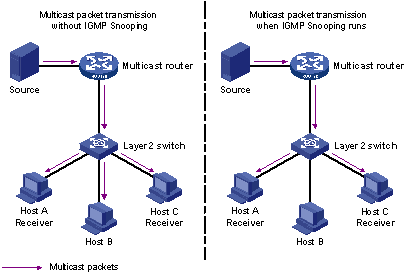
Figure 3-1 Multicast packet transmission with or without IGMP Snooping being enabled
3.1.2 IGMP Snooping Implementation
I. IGMP Snooping terminologies
Before going on, we first describe the following IGMP Snooping related terms:
l Router port: the switch port directly connected to the multicast router.
l Multicast member port: a switch port connected to a multicast group member (a host in a multicast group).
l MAC multicast group: a multicast group identified by a MAC multicast address and maintained by the switch.
The following three timers are closely associated with IGMP snooping.
Table 3-2 IGMP Snooping timers
|
Timer |
Setting |
Packet normally received before timeout |
Timeout action on the switch |
|
Router port aging timer |
Aging time of the router port |
IGMP general query message/PIM message/DVMRP probe message |
Consider that this port is not a router port any more. |
|
Multicast group member port aging timer |
Aging time of the multicast group member ports |
IGMP message |
Send an IGMP group-specific query message to the multicast member port. |
|
Query response timer |
Query response timeout time |
IGMP report message |
Remove the port from the member port list of the multicast group. |
II. Layer 2 multicast with IGMP Snooping
The switch runs IGMP Snooping to listen to IGMP messages and establish mapping among the host, the port corresponding to the host, and the corresponding multicast MAC address.
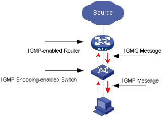
Figure 3-2 IGMP Snooping implementation
To implement Layer 2 multicast, the switch processes four different types of IGMP messages it received, as shown in Table 3-3.
Table 3-3 IGMP Snooping messages
|
Message |
Sender |
Receiver |
Purpose |
Action of the multicast member switch |
|||||
|
IGMP general query message |
Multicast router and multicast switch |
Multicast member switch and host |
Query if the multicast groups contain any member |
Check if the message comes from the original router port |
If yes, reset the aging timer of the router port |
||||
|
If not, notify all the members of the multicast router to join a specific multicast group and start the aging timer for the router port |
|||||||||
|
IGMP group-specific query message |
Multicast router and multicast switch |
Multicast member switch and host |
Query if a specific IGMP multicast group contains any member |
Send an IGMP group-specific query message to the IP multicast group being queried. |
|||||
|
IGMP host report message |
Host |
Multicast router and multicast switch |
Apply for joining a multicast group, or respond to an IGMP query message |
Check if the IP multicast group has a corresponding MAC multicast group |
If yes, check if the port exists in the MAC multicast group |
If yes, add the IP multicast group address to the MAC multicast group table. |
|||
|
If not, add the port to the MAC multicast group, reset the aging timer of the port and check if the corresponding IP multicast group exists. |
If yes, add the port to the IP multicast group. |
||||||||
|
If not, create an IP multicast group and add the port to it. |
|||||||||
|
If not: l Create a MAC multicast group and notify the multicast router that a member is ready to join the multicast group. l Add the port to the MAC multicast group and start the aging timer of the port. l Add all router ports in the VLAN owning this port to the MAC multicast group. l Add the port to the new IP multicast group. |
|||||||||
|
IGMP leave message |
Host |
Multicast router and multicast switch |
Notify the multicast router and multicast switch that the host is leaving its multicast group. |
Multicast router and multicast switch send IGMP specific group query message(s) to the multicast group whose member host sends leave messages to check if the multicast group has any member and enable the corresponding query timer. |
The switch checks whether the port is the last host port in the corresponding MAC multicast group. l If yes, remove the corresponding MAC multicast group and IP multicast group l If not, remove only those entries corresponding to this port in the MAC multicast group, and remove the corresponding entries in the IP multicast group |
||||
|
If no response is received from the multicast group before the timer times out, notify the router to remove this multicast group node from the multicast tree |
|||||||||
![]() Caution:
Caution:
An IGMP Snooping-enabled S7500 Ethernet switch judges whether the multicast group exists when it receives an IGMP leave message sent by a host in a multicast group. If this multicast group does not exist, the switch will drop the IGMP leave message instead of forwarding it.
3.2 IGMP Snooping Configuration
Complete the following tasks to configure IGMP Snooping:
|
Task |
Remarks |
|
Required |
|
|
Optional |
|
|
Optional |
|
|
Optional |
|
|
Configuring to Limit the Number of Multicast Groups on a Port |
Optional |
|
Optional |
|
|
Optional |
3.2.1 Enabling IGMP Snooping
You can use the command here to enable IGMP Snooping so that it can establish and maintain forwarding tables for MAC multicast groups at layer 2.
Follow these steps to enable IGMP Snooping:
|
To do... |
Use the command... |
Remarks |
|
Enter system view |
system-view |
— |
|
Enable IGMP Snooping globally |
igmp-snooping enable |
Required By default, IGMP Snooping is disabled globally. |
|
Enter VLAN view |
vlan vlan-id |
— |
|
Enable IGMP Snooping in the VLAN |
igmp-snooping enable |
Required By default, IGMP Snooping is disabled in the VLAN. |
![]() Caution:
Caution:
l Although both Layer 2 and Layer 3 multicast protocols can run on the same switch simultaneously, they cannot run simultaneously in a VLAN or its corresponding virtual interface.
l Before enabling IGMP Snooping in VLAN view, you must enable IGMP Snooping globally in system view. Otherwise, the IGMP Snooping feature cannot be enabled in VLAN view.
3.2.2 Configuring Timers
This configuration task is to manually configure the aging timer of the router port, the aging timer of the multicast member ports, and the query response timer.
l If the switch receives no IGMP general query message from a router within the aging time of the router port, the switch removes the router port from the port member lists of all MAC multicast groups.
l If the switch receives no IGMP host report message, it sends an IGMP group-specific query message to the port and triggers the query response timer of the IP multicast group.
l If the switch receives no IGMP host report message within the aging time of the member port, it sends an IGMP group-specific query message to the port and triggers the query response timer of the IP multicast group.
Follow these steps to configure timers:
|
To do... |
Use the command... |
Remarks |
|
Enter system view |
system-view |
— |
|
Configure the aging timer of the router port |
igmp-snooping router-aging-time seconds |
Optional By default, the aging time of the router port is 105 seconds. |
|
Configure the query response timer |
igmp-snooping max-response-time seconds |
Optional By default, the query response timeout time is 10 seconds. |
|
Configure the aging timer of the multicast member port |
igmp-snooping host-aging-time seconds |
Optional By default, the aging time of multicast member ports is 260 seconds. |
3.2.3 Enabling IGMP Fast Leave
Normally, when receiving an IGMP Leave message, the IGMP Snooping-enabled switch does not immediately remove the port from the multicast group, but sends an IGMP group-specific query message. If no response is received in a given period, it then removes the port from the multicast group.
If the IGMP fast leave feature is enabled, when receiving an IGMP Leave message, the IGMP Snooping-enabled switch immediately removes the port from the multicast group. When a port has only one user, enabling the IGMP fast leave feature on the port can save bandwidth.
I. Enable the IGMP fast leave feature for all ports globally
Follow these steps to enable the IGMP fast leave feature for all ports globally:
|
To do... |
Use the command... |
Remarks |
|
Enter system view |
system-view |
— |
|
Enable the fast leave feature from the multicast group of the specific VLAN for all port |
igmp-snooping fast-leave [ vlan vlan-list ] |
Optional By default, the fast leave feature from a multicast group for all ports is disabled. |
II. Enable the fast leave feature for a port
Follow these steps to enable the fast leave feature for a port:
|
To do... |
Use the command... |
Remarks |
|
Enter system view |
system-view |
— |
|
Enter Ethernet port view |
interface interface-type interface-number |
— |
|
Enable the port to fast leave from the multicast group(s) of the specific VLAN(s) |
igmp-snooping fast-leave [ vlan vlan-list ] |
Optional By default, the fast leave feature is disabled. |
3.2.4 Configuring IGMP Snooping Filtering ACLs
You can configure multicast filtering ACLs on the switch ports connected to users so as to use the IGMP Snooping filtering feature to limit the multicast streams that the users can access. With this feature, you can treat different VoD users in different ways by allowing them to access the multicast streams in different multicast groups.
In practice, when a user orders a multicast program, an IGMP report message is generated. When the message is received on a switch, the switch checks the multicast filtering ACL configuration on the receiving port to determine whether the port can join the corresponding multicast group. If yes, it adds the port to the forwarding port list of the multicast group. If not, it drops the IGMP report message and does not forward the corresponding data streams to the port. In this way, you can control the multicast streams that users can access.
Make sure that ACL rules have been configured before configuring this feature.
Follow these steps to configure IGMP Snooping filtering ACLs:
|
To do... |
Use the command... |
Remarks |
|
Enter system view |
system-view |
— |
|
Enable the IGMP Snooping filtering feature in system view |
igmp-snooping group-policy acl-number [ vlan vlan-list ] |
Optional l You can configure the ACL to filter the IP addresses of corresponding multicast groups. l By default, the multicast filtering feature is disabled. |
|
Enter Ethernet port view |
interface interface-type interface-number |
— |
|
Configure the multicast filtering feature on the port |
igmp-snooping group-policy acl-number [ vlan vlan-list ] |
Optional l You can configure the ACL to filter the IP addresses of the corresponding multicast group. l By default, the multicast filtering feature is disabled. |
& Note:
l One port can belong to multiple VLANs. Only one ACL rule can be configured in each of the VLANs to which the port belongs.
l If the port does not belong to the VLAN where the command is configured, the configured ACL rule does not take effect.
l If no ACL rule is configured in the command, the multicast packets of all the multicast groups are rejected.
l Most devices broadcast unknown multicast packets. In order that multicast packets are not sent to filtered ports as unknown multicast packets, this feature is generally used together with the unknown multicast drop function.
3.2.5 Configuring to Limit the Number of Multicast Groups on a Port
With limit imposed on the number of multicast groups on a switch port, users can no longer have as many multicast groups as they want when demanding programs in multicast groups. Thereby, the bandwidth on the port is controlled.
Follow these steps to configure to limit number of multicast groups on a port:
|
To do... |
Use the command... |
Remarks |
|
Enter system view |
system-view |
— |
|
Enter Ethernet port view |
interface interface-type interface-number |
— |
|
Limit the number of multicast groups on a port |
igmp-snooping group-limit limit [ vlan vlan-list [ overflow-replace ] | overflow-replace] |
Optional The number of multicast groups on a port is not limited by default. |
3.2.6 Configuring Suppression on IGMP Report Messages
When a Layer 2 switch receives IGMP report messages from a host in a multicast group, the switch will forward the packets to the port of a Layer 3 switch that is connected to it. In this way, a Layer 3 switch will receive the same IGMP report messages from multiple hosts in a multicast group when there are multiple hosts in this multicast group.
When suppression on IGMP report messages is enabled, in a query interval, the Layer 2 switch will forward only the first IGMP report message from a multicast group to the Layer 3 switch, and drop the other IGMP report messages from the same multicast group.
Follow these steps to configure suppression on IGMP report messages:
|
To do... |
Use the command... |
Remarks |
|
Enter system view |
system-view |
— |
|
Configure suppression on IGMP report messages |
report-aggregation |
Required By default, suppression on IGMP report messages is disabled. |
3.2.7 Configuring Multicast VLAN
In the current multicast mode, when users in different VLANs order the same stream, the multicast stream is copied to each of the VLANs. This mode wastes a lot of bandwidth.
By configuring a multicast VLAN, adding switch ports to the multicast VLAN and enabling IGMP Snooping, you can make users in different VLANs share the same multicast VLAN. This saves bandwidth because multicast streams are transmitted only within the multicast VLAN and also guarantees security because the multicast VLAN is isolated from user VLANs completely. Therefore, multicast information streams can be transmitted to users continuously if multicast VLAN is configured.
Perform the following configurations to configure multicast VLAN.
Follow these steps to configure multicast VLAN:
|
To do... |
Use the command... |
Remarks |
|
Enter system view |
system-view |
— |
|
Enable the IGMP snooping feature globally |
igmp-snooping enable |
Required |
|
Enter VLAN view |
vlan vlan-id |
— |
|
Enable the IGMP snooping feature in VLAN view |
igmp-snooping enable |
Required |
|
Enable the multicast VLAN feature in VLAN view |
multicast-vlan enable |
Required |
|
Quit VLAN view |
quit |
— |
|
Configure the mapping relationship between multicast VLAN and multicast sub-VLANs |
multicast-vlan vlan-id subvlan vlan-list |
Required |
![]() Caution:
Caution:
l A multicast VLAN cannot be configured as a multicast sub-VLAN.
l A multicast sub-VLAN cannot be configured as a multicast VLAN.
l A multicast sub-VLAN cannot be configured as the sub-VLAN of another multicast VLAN.
l A multicast sub-VLAN corresponds to only one multicast VLAN.
l If multicast routing is enabled on a VLAN interface by using the multicast routing-enable command, the corresponding VLAN cannot be configured as a multicast VLAN.
l Every Ethernet switch supports up to 5 multicast VLANs,
3.3 Displaying and Maintaining IGMP Snooping
|
Use the command... |
Remarks |
|
|
Display the current IGMP Snooping configuration |
display igmp-snooping configuration |
Available in any view |
|
Display IGMP Snooping message statistics |
display igmp-snooping statistics |
|
|
Display information about IP and MAC multicast groups in one or all VLANs |
display igmp-snooping group [ vlan vlanid ] |
|
|
Display the configuration of the multicast VLAN |
display multicast-vlan [ vlan-id ] |
|
|
Clear IGMP Snooping statistics |
reset igmp-snooping statistics |
Available in user view |
3.4 IGMP Snooping Configuration Examples
3.4.1 Example 1
Implement IGMP Snooping on a switch.
I. Network requirements
Connect the router port on the switch to the router, and other non-router ports belonging to VLAN 10 to user PCs. Enable IGMP Snooping on the switch.
II. Network diagram
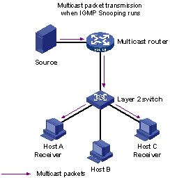
Figure 3-3 Network diagram for IGMP Snooping configuration
III. Configuration procedure
# Enable IGMP Snooping in system view globally.
<H3C> system-view
[H3C] igmp-snooping enable
# Enable IGMP Snooping in VLAN 10 where no Layer 3 multicast protocol is enabled.
[H3C] vlan 10
[H3C-vlan10] igmp-snooping enable
3.4.2 Example 2
Implement multicast VLAN on switches.
I. Network requirements
Table 3-4 lists all the devices in the network. Assume that port type configuration, VLAN division configuration, and IP address configuration for VLAN interfaces are completed.
Table 3-4 List of network device configurations
|
Device ID |
Device type |
Port |
Device connected to the port |
Description |
|
Router A |
Router |
GigabitEthernet0/0/0 |
Switch B |
GigabitEthernet0/0/0 belongs to VLAN1024, where the PIM-SM and IGMP protocols are enabled. |
|
Switch B |
Layer 3 switch |
GigabitEthernet2/0/1 GigabitEthernet2/0/2 GigabitEthernet2/0/3 |
Router A Switch C Switch D |
GigabitEthernet2/0/1 belongs to VLAN1024. GigabitEthernet2/0/2 is a trunk port belonging to VLAN 2 through VLAN 4. GigabitEthernet2/0/3 is a trunk port belonging to VLAN 5 through VLAN 7. |
|
Switch C |
Layer 2 switch |
The port connecting to the upper-layer switch is configured as a trunk port. |
— |
Switch C is connected to users belonging to VLAN 2 through VLAN 4 where the IGMP snooping feature is enabled. |
|
Switch D |
Layer 2 switch |
The port connecting to the upper-layer switch is configured as a trunk port. |
— |
Switch C is connected to users belonging to VLAN 5 through VLAN 7 where the IGMP snooping feature is enabled. |
Configure VLAN 1024 as a multicast VLAN and configure VLAN 2 through VLAN 7 as multicast sub-VLANs.
II. Network diagram
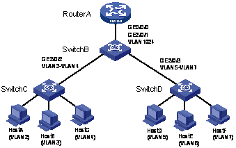
Figure 3-4 Network diagram for multicast VLAN configuration
III. Configuration procedure
# Configure Router A.
<Router-A> system-view
[Router-A] multicast routing-enable
[Router-A] interface GigabitEthernet0/0/0
[Router-A-GigabitEthernet0/0/0] pim sm
[Router-A-GigabitEthernet0/0/0] igmp enable
[Router-A-GigabitEthernet0/0/0] quit
[Router-A]
# Configure Switch B.
<H3C> system-view
[H3C] igmp-snooping enable
[H3C] vlan 1024
[H3C-vlan1024]igmp-snooping enable
[H3C-vlan1024] multicast-vlan enable
[H3C-vlan1024] quit
[H3C] multicast-vlan 1024 subvlan 2 to 7
3.5 Troubleshooting IGMP Snooping
Symptom: Multicast does not work on the switch.
Solution:
The reason may be:
1) IGMP Snooping is not enabled.
l Use the display current-configuration command to check the status of IGMP Snooping.
l If IGMP Snooping is disabled, check whether it is disabled globally or in the corresponding VLAN. If it is disabled globally, use the igmp-snooping enable command in both system view and VLAN view to enable it both globally and in the corresponding VLAN at the same time. If it is only disabled in the corresponding VLAN, use the igmp-snooping enable command in VLAN view only to enable it in the corresponding VLAN.
2) Multicast forwarding tables set up by IGMP Snooping are wrong.
l Use the display igmp-snooping group command to check if the multicast groups are expected ones.
l If the multicast group set up by IGMP Snooping is not correct, contact your technical support personnel.
l Continue with solution 3) if the second step does not work.
If it is not the reason, the possible reason may be:
3) MAC multicast forwarding tables set up by IGMP Snooping are wrong.
l If they are not consistent, contact your technical support personnel.
Chapter 4 Common Multicast Configuration
4.1 Overview
Common multicast configuration tasks are the common contents of the multicast group management protocol and the multicast routing protocol. You must enable the common multicast configuration on the switch before enabling the two protocols.
Common multicast configuration includes:
l Configuring limit on the number of route entries: when the multicast routing protocol is configured on a switch, plenty of multicast route entries will be sent to upstream Layer 3 switches or routers. In order to prevent plenty of multicast route entries from consuming all the memory of the Layer 3 switches or routers, you can configure limit on the number of route entries to prevent too many route entries from being sent to Layer 3 switches or routers.
l Configuring suppression on the multicast source port: In the network, some users may set up multicast servers privately, which results in the shortage of multicast network resources and affects the multicast bandwidth and the transmission of valid information in the network. You can configure suppression on the multicast source port to filter multicast packets on the unauthorized multicast source port, so as to prevent the users connected to the port from setting up multicast servers privately.
l Clearing the related multicast entries: through clearing the related multicast entries, you can clear the multicast route entries saved in the memory of the Layer 3 switches or routers to release the system memory.
4.2 Common Multicast Configuration
Complete the following tasks to perform common multicast configuration:
|
Task |
Remarks |
|
Enabling Multicast and Configuring Limit on the Number of Route Entries |
Required |
|
Optional |
|
|
Optional |
|
|
Optional |
|
|
Optional |
4.2.1 Enabling Multicast and Configuring Limit on the Number of Route Entries
Follow these steps to enable multicast and configure limit on the number of route entries:
|
To do... |
Use the command... |
Remarks |
|
Enter system view |
system-view |
— |
|
Enable multicast |
multicast routing-enable |
Required Multicast must be enabled before the multicast group management protocol and the multicast routing protocol are enabled. |
|
Configure limit on the number of multicast route entries |
multicast route-limit limit |
Required By default, the limit on the number of multicast route entries is 1,024. |
![]() Caution:
Caution:
The other multicast configurations do not take effect until multicast is enabled.
4.2.2 Configuring Suppression on the Multicast Source Port
I. Configure suppression on the multicast source port in system view
Follow these steps to configure suppression on the multicast source port in system view:
|
To do... |
Use the command... |
Remarks |
|
Enter system view |
system-view |
— |
|
Configure suppression on the multicast source port |
multicast-source-deny enable [ interface interface-list ] |
Required Suppression on the multicast source port is disabled by default. |
II. Configure suppression on the multicast source port in Ethernet port view
Follow these steps to configure suppression on the multicast source port in Ethernet port view:
|
To do... |
Use the command... |
Remarks |
|
Enter system view |
system-view |
— |
|
Enter Ethernet port view |
interface interface-type interface-number |
— |
|
Configure suppression on the multicast source port in Ethernet port view |
multicast-source-deny enable |
Optional Suppression on the multicast source port is disabled on all ports of the switch by default. |
4.2.3 Configuring Suppression on Multicast Wrongif Packets
I. Introduction
When the switch receives a multicast packet, the switch will search the multicast forwarding entry according to the source address and destination address of the packet. If the matching forwarding entry is found and the packet is received on the right incoming interface of the forwarding entry, the packet will be forwarded according to the forwarding entry. If the packet is not received on the right incoming interface of the forwarding entry, the packet is regarded as a wrongif packet. The wrongif packet will be reported to the CPU.
In some network, many wrongif packets will be reported to the CPU of the switch, thus aggravating the workload of the switch. In this case, you can configure suppression on the holdtime of wrongif packets, so that the wrongif packets will be dropped instead of being forwarded to the CPU of the switch, and the CPU will be prevented from being stricken by too many packets.
II. Suppression on the holdtime of multicast wrongif packets
Follow these steps to configure suppression on the holdtime of multicast wrongif packets:
|
To do... |
Use the command... |
Remarks |
|
Enter system view |
system-view |
— |
|
Configure suppression on the holdtime of multicast wrongif packets |
multicast wrongif-holdtime seconds |
Required By default, the holdtime of multicast wrongif packets is 15 seconds. |
![]() Caution:
Caution:
l During the configuration, if the seconds argument is less than 15, the system sets the holdtime to 15; if the seconds argument is more than 15, the system sets the holdtime to the multiples of 15 according to the user-defined range. For example, if you set the seconds argument to 14, the system sets the holdtime to 15; if you set the seconds argument to 16, the system sets the holdtime to 30; if you set the seconds argument to 31, the system sets the holdtime to 45, and so on.
l When the holdtime is set to 0, the report of CPU packets to the CPU is not suppressed.
4.2.4 Configuring Static Router Ports
I. Introduction
In a ring network or a network with double uplinks, users usually configure both primary and secondary links over a connection in order to avoid communication interruption due to link failure. When the primary link fails, the secondary link can replace it immediately to avoid communication interruption.
On a link with a multicast protocol (such as PIM or IGMP) enabled, the switch cannot restore multicast data transmission after switchover until the switch receives multicast messages (such as PIM Hello messages and IGMP general group query messages) and adds the static router port to the corresponding multicast entry. The process will cause temporary interruption of multicast data transmission. For real-time services such as IPTV, the delay will cause some undesirable problems such as picture jitter.
You can configure a port as a static router port to solve this problem. When the link state switches, the multicast data can be switched from the primary link to the secondary link immediately, so that the switch need not wait for multicast protocol messages and the multicast data transmission delay is avoided. Additionally, a static port never times out except when a link fails or the configuration is removed.
II. Configuring static router ports
Configure static router ports as follows:
l Enable IGMP snooping globally
l Enable multicast routing globally
l Allocate an Ethernet port to the corresponding VLAN
l Configure an IP address for the VLAN
l Enable the multicast routing protocol on the VLAN interface
l Bring the Ethernet port to the up state
Follow these steps to configure static router ports:
|
To do... |
Use the command... |
Remarks |
|
Enter system view |
system-view |
— |
|
Enter Ethernet port view |
interface interface-type interface-number |
— |
|
Configure static router ports |
multicast static-router-port vlan vlan-id |
Required |
|
Exit port view |
quit |
— |
|
Enter VLAN view |
vlan vlan-id |
— |
|
Configure static router ports |
multicast static-router-port interface interface-type interface-number |
Required |
![]() Caution:
Caution:
You can configure static router ports in Ethernet port view or VLAN view, but you can view the related configuration information in Ethernet port view only.
III. Configuration example
# Configure Ethernet2/0/1 in VLAN 2 as a static router port.
<H3C> system-view
[H3C] interface Ethernet 2/0/1
[H3C-Ethernet2/0/1] multicast static-router-port vlan 2
4.2.5 Clearing Multicast Related Entries
Use the reset command in user view to clear the related statistics information about the common multicast configuration.
Follow these steps to clear multicast related entries:
|
To do... |
Use the command... |
Remarks |
|
Clear the forwarding entries in the multicast forwarding cache (MFC) or the statistics information about the forwarding entries in the MFC |
reset multicast forwarding-table [ statistics ] { all | { group-address [ mask { group-mask | group-mask-length } ] | source-address [ mask { source-mask | source-mask-length } ] | incoming-interface interface-type interface-number } * } |
Clear the related forwarding entries in the MFC |
|
Clear the route entries in the core multicast routing table |
reset multicast routing-table { all | { group-address [ mask { group-mask | group-mask-length } ] | source-address [ mask { source-mask | source-mask-length } ] | { incoming-interface interface-type interface-number } } * } |
Clear the route entries in the core multicast routing table |
4.3 Displaying and Maintaining Common Multicast Configuration
|
Use the command... |
Remarks |
|
|
Display the statistics information about suppression on the multicast source port |
display multicast-source-deny [ interface interface-type [ interface-number ] ] |
Available any view. l If neither the port type nor the port number is specified, the statistics information about the suppression on all the multicast source ports on the switch is displayed. l If only the port type is specified, the statistics information about the suppression on the multicast source ports of the type is displayed. l If both the port type and the port number are specified, the statistics information about the suppression on the specified multicast source port is displayed. |
|
Display the information about the multicast routing table |
display multicast routing-table [ group-address [ mask { group-mask | mask-length } ] | source-address [ mask { group-mask | mask-length } ] | incoming-interface { interface-type interface-number | register } ]* |
Available in any view |
|
Display the information about the multicast forwarding table |
display multicast forwarding-table [ group-address [ mask { group-mask | mask-length } ] | source-address [ mask { group-mask | mask-length } ] | incoming-interface { interface-type interface-number ] register } ]* |
|
|
Display the information about the multicast forwarding tables containing port information |
display mpm forwarding-table [ group-address ] |
|
|
Display the information about IP multicast groups and MAC multicast groups in one VLAN or all the VLANs on the switch |
display mpm group [ vlan vlan-id ] |
Three kinds of tables affect data transmission. The correlations of them are:
l Each multicast routing protocol has its own multicast routing table.
l The multicast routing information of all multicast routing protocols is integrated to form the core multicast routing table.
l The core multicast routing table is consistent with the multicast forwarding table, which is in really in charge of multicast packet forwarding.
Chapter 5 Multicast MAC Address Entry Configuration
5.1 Overview
In Layer 2 multicast, the system can create multicast forwarding entries dynamically through Layer 2 multicast protocol. However, you can also statically bind a port to a multicast address entry by configuring a multicast MAC address entry manually.
Generally, when receiving a multicast packet whose multicast address has not yet been registered on the switch, the switch will broadcast the packet in the VLAN to which the port belongs. However, you can configure a static multicast MAC address entry to avoid this case.
5.2 Configuring a Multicast MAC Address Entry
You can configure multicast MAC address entries in system view.
Follow these steps to configure a multicast MAC address entry in system view:
|
To do... |
Use the command... |
Remarks |
|
Enter system view |
system-view |
— |
|
Create a multicast MAC address entry |
mac-address multicast mac-address interface interface-list vlan vlan-id |
Required l The mac-address argument must be a multicast MAC address l The vlan-id argument is the ID of the VLAN to which the port belongs |
& Note:
l If the multicast MAC address entry to be created already exists, the system gives you a prompt.
l If a multicast MAC address is added manually, the switch will not learn this multicast MAC address again through IGMP Snooping. The undo mac-address multicast command is used to remove the multicast MAC address entries created by the mac-address multicast command manually, however, it cannot be used to remove the multicast MAC address entries learned by the switch.
l If you want to add a port to a multicast MAC address entry created through the mac-address multicast command, you must remove this entry first, create this entry again, and then add the specified port to the forwarding ports of this entry.
l You cannot enable link aggregation on a port where you have configured a multicast MAC address; and you cannot configure a multicast MAC address on an aggregation port.
5.3 Displaying and Maintaining Multicast MAC Address
|
To do... |
Use the command... |
Remarks |
|
Display the multicast MAC address entry/entries manually configured |
display mac-address multicast [ count ] |
Available in any view. |
Chapter 6 IGMP Configuration
6.1 Overview
6.1.1 Introduction to IGMP
Internet group management protocol (IGMP) is responsible for the management of IP multicast members. It is used to establish and maintain membership between IP hosts and their directly connected neighboring multicast routers.
However, the IGMP feature does not transmit and maintain the membership information between multicast routers. This task is completed by multicast routing protocols. All multicast host must have IGMP enabled.
IGMP is divided into two function parts:
l Host side: an IP multicast host can join or exit a multicast group anywhere and anytime, without being restricted by the total number of group members.
l Router side: through the IGMP protocol, a multicast router checks the network segment connected with each interface to see whether there are receivers of a multicast group, namely, group members.
A multicast router need not and cannot save the membership information of all the hosts. However, a host must save the information about the multicast groups it joins in.
IGMP is asymmetric between the host and the router. The host needs to use IGMP report messages to respond to the IGMP query messages of the multicast routers. The multicast router sends IGMP general query messages periodically and determines whether any host of a specified group joins in its subnet based on the received response messages. When the router receives IGMP leave messages, it will send IGMPv2 group-specific query messages to find out whether the specified group still has any member.
6.1.2 IGMP Version
IGMP has three versions until now, including: IGMPv1 defined by RFC1112, IGMPv2 defined by RFC2236 and IGMPv3. IGMPv2 is the most widely used currently.
Compared with IGMPv1, the advantages of IGMPv2 are:
I. Multicast router election mechanism on a shared network segment
A shared network segment is a network segment with multiple multicast routers. In this case, all routers running IGMP on this network segment can receive the membership report messages from hosts. Therefore, only one router is necessary to send membership query messages. In this case, the querier selection mechanism is required to specify a router as the querier.
In IGMPv1, the multicast routing protocol selects the querier. In IGMPv2, it is defined that the multicast router with the lowest IP address is selected as the querier when there are multiple multicast routers in a network segment.
II. Leave group mechanism
In IGMPv1, hosts leave the multicast group quietly without informing any multicast router. Only when a query message times out can the multicast router know that a host has left the group. In IGMPv2, when a host replying to the last membership query message decides to leave a multicast group, it will send a leave group message to the multicast router.
III. Group-specific query
In IGMPv1, a multicast query message of the multicast router aims at all the multicast groups in the network segment. This query is called general query.
IGMPv2 adds group-specific query, where the IP address of a multicast group is taken as the destination IP address and the group address field of the query message, to prevent the member hosts of other groups from responding to this message.
IV. Maximum response time
The Maximum Response Time field is added in IGMPv2. It is used to dynamically adjust the maximum time for a host to respond to the membership query message.
6.1.3 Working Procedure of IGMP
The working procedure of IGMP is as follows:
l The receiver host reports the membership to its shared network.
l A querier (IGMPv2) is selected from all the IGMP-enabled routers in the same network segment.
l The querier periodically sends query messages to the shared network segment.
l The receiver host responds to the received query message to report the group membership.
l The querier refreshes the presence information of the group members according to the received responses.
IGMP must be enabled on all the multicast receiver hosts. An IP multicast host can join in or exit a multicast group anywhere and anytime, without being restricted by the total number of group members.
The multicast router need not and cannot save the membership information of all the hosts. It just checks the network segment connected with each interface by IGMP to see whether there are receivers of a multicast group, namely, group members. While each host saves only the information about the multicast groups it joins.
I. Working mechanism of IGMPv1
Comware implements the IGMPv1 protocol according to RFC1112. IGMPv1 manages the multicast groups based on the query/response mechanism. With the help of Layer 3 routing protocols, IGMP selects the designated router (DR) as the querier responsible for sending query messages. Figure 6-1 describes the IGMPv1 message interaction in the network:
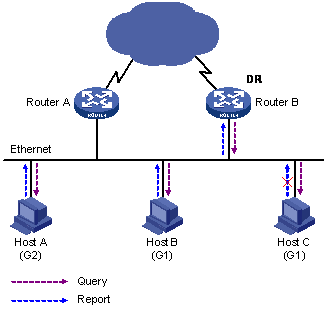
Figure 6-1 Working mechanism of IGMPv1
A host joins in the multicast group in the following procedure:
l The IGMP querier (such as DR) periodically multicasts IGMP general group query messages to all the hosts in the shared network segment whose address is 224.0.0.1.
l All hosts in the network receive the query messages. If some hosts (such as Host B and Host C) are interested in multicast group G1, Host B and Host C will multicast IGMP report messages (carrying the address of multicast group G1) to declare that they will join in multicast group G1.
l All the hosts and routers in the network receive the IGMP report messages and get to know the address of multicast group G1. In this case, if other hosts in the network want to join in multicast group G1, they will not send IGMP report messages about G1. If some hosts in the network want to join in another multicast group G2, they will send IGMP report messages about G2 to respond to the query messages.
l After the query/response process, the IGMP routers get to know that receivers of multicast group G1 exist in the network, and generate the (*, G1) multicast forwarding entries, according to which multicast data is forwarded.
l The data from the multicast source reaches the IGMP router over the multicast routes. If there are receivers in the network connected to the IGMP router, the data will be forwarded to this network segment and the receiver hosts receive the data.
IGMP leave messages are not defined in IGMPv1. When a host leaves a multicast group, the multicast router knows that a host has left the group only when the query message times out.
When all the hosts in a network segment have left the multicast group, the branch corresponding to the related network segment is pruned from the multicast tree.
6.1.4 IGMP Proxy
A lot of leaf networks (leaf domains) are involved in the application of a multicast routing protocol (PIM-DM for example) over a large-scaled network. It is a hard work to configure and manage these leaf networks.
To reduce the workload of configuration and management without affecting the multicast connection of leaf networks, you can configure an IGMP Proxy in a Layer 3 switch in the leaf network (Switch B in the figure). The Layer 3 switch will then forward IGMP join or IGMP leave messages sent by the connected hosts. After the configuration of IGMP Proxy, the leaf switch is no longer a PIM neighbor but a host for the external network. Only when the Layer 3 switch has directly connected members, can it receive the multicast data of corresponding groups.
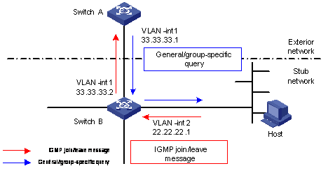
Figure 6-2 Diagram for IGMP Proxy
Figure 6-2 is an IGMP Proxy diagram for a leaf network.
Configure Switch B as follows:
l Enable multicast routing on VLAN interface 1 and VLAN interface 2, and then configure the PIM protocol on it. And configure the IGMP protocol on VLAN-interface 1 at the same time.
l On VLAN interface 2, configure VLAN interface 1 as the outbound IGMP Proxy interface to external networks. You must enable the IGMP protocol on the interface first, and then configure the igmp proxy command.
Configure Switch A as follows:
l Enable multicast routing and configure the IGMP protocol on VLAN interface 1.
l Configure the pim neighbor-policy command to filter PIM neighbors in the network segment 33.33.33.0/24. That is, Switch A does not consider Switch B as its PIM neighbor.
In this case, when VLAN interface 2 of Switch B of the leaf network receives an IGMP join or IGMP leave message sent by the host, it will change the source address of the IGMP message into the address of VLAN interface 1 (33.33.33.2) and send the information to VLAN interface 1 of Switch A. For Switch A, this works as if there is a host directly connected to VLAN interface 1.
Similarly, when Switch B receives an IGMP general group or group-specific query message from the Layer 3 Switch A, it will also change the source address of the query message into the IP address of VLAN interface 2 (22.22.22.1) and send the message from VLAN interface 2.
In Figure 6-2, VLAN interface 2 of Switch B is called the client interface and VLAN interface 1 of Switch B is called the proxy interface.
6.2 IGMP Configuration
Complete the following tasks to configure IGMP:
|
Task |
Remarks |
|
Optional |
|
|
Optional |
|
|
Optional |
|
|
Configuring Router Ports to Join the Specified Multicast Group |
Optional |
|
Optional |
|
|
Optional |
|
|
Optional |
6.2.1 Configuring IGMP Version
Follow these steps to configure IGMP version:
|
To do... |
Use the command... |
Remarks |
|
Enter system view |
system-view |
— |
|
Enable the multicast routing protocol |
multicast routing-enable |
Enable the multicast routing protocol. |
|
Enter VLAN interface view |
interface Vlan-interface interface-number |
— |
|
Enable IGMP on the current interface |
igmp enable |
Required By default, if IP multicast routing is enabled globally, IGMP is enabled on all the layer-3 interfaces automatically. |
|
Configure the IGMP version for the Layer 3 switch (router) |
igmp version { 1 | 2 } |
Optional IGMPv2 is used by default. |
![]() Caution:
Caution:
An IGMP version cannot be switched to other versions automatically. So all the Layer 3 switches on a subnet must be configured to use the same IGMP version.
6.2.2 Configuring IGMP Query Messages
I. IGMP general query messages
The Layer 3 switch sends IGMP general query messages to the connected network segment periodically to get to know which multicast groups in the network segment have members according to the returned IGMP report messages. The multicast router also sends query messages periodically. When it receives the IGMP report message of a group member, it will refresh the membership information of the network segment.
II. IGMP group-specific messages
The query router (querier for short) maintains the IGMP report messages on interfaces of the shared network. After the related features are configured, the IGMP querier will send IGMP group-specific query messages at the user-defined interval for the user-defined times when it receives the IGMP leave messages from the host.
Suppose a host in a multicast group decides to leave the multicast group. The detailed procedures are as follows:
l The host sends an IGMP leave message.
l When the IGMP querier receives the message, it will send IGMP group-specific query messages at the interval configured by the igmp lastmember-queryinterval command (the interval is 1 second by default) for the robust-value times (the robust-value argument is configured by the igmp robust-count command and it is 2 by default).
l If other hosts are interested in the group after receiving the IGMP group-specific query message from the querier, they will send IGMP report messages in the maximum response time specified in the message.
l If the IGMP querier receives IGMP join messages from other hosts within the robust-value x seconds time, it will maintain the membership of the group.
l If the IGMP querier does not receive IGMP report messages from other hosts after the robust-value x seconds time, it considers the group times out and will not maintain the membership of the group.
The procedures are only applicable to the occasion where IGMP queriers run IGMPv2.
If the host runs IGMPv1, it does not send IGMP leave messages when leaving a group, so the conditions will not be the same as described in the procedures above.
III. IGMP querier substitution rules
The lifetime of an IGMP querier is limited. If the former querier does not send query messages in the specified time, another router will replace the IGMP querier.
IV. The maximum query time of IGMP messages
When the host receives a query message, it will set a timer for each of its multicast groups. The timer value is selected from 0 to the maximum response time at random. When the value of a timer decreases to 0, the host will send the membership information of the multicast group.
Through configuring the reasonable maximum response time, you can enable the host to respond to the query messages quickly and enable the Layer 3 switch to know the membership information of each multicast group quickly.
Follow these steps to configure IGMP query messages:
|
To do... |
Use the command... |
Remarks |
|
Enter system view |
system-view |
— |
|
Enable the multicast routing protocol |
multicast routing-enable |
Enable the multicast routing protocol. |
|
Enter VLAN interface view |
interface Vlan-interface interface-number |
— |
|
Enable IGMP on the current interface |
igmp enable |
Required By default, if the IP multicast routing protocol is enabled globally, IGMP is enabled on all the layer-3 interfaces automatically. |
|
Configure the query interval |
igmp timer query seconds |
Optional The query interval is 60 seconds by default. |
|
Configuring the interval of sending IGMP group-specific query messages |
igmp lastmember-queryinterval seconds |
Optional By default, the interval of sending IGMP group-specific query messages is 1 second. |
|
Configuring the times of sending IGMP group-specific query messages |
igmp robust-count robust-value |
Optional By default, the times of sending IGMP group-specific query messages is 2. |
|
Configure the maximum lifetime of an IGMP querier |
igmp timer other-querier-present seconds |
Optional l The lifetime of an IGMP querier is 120 seconds by default. l If the Layer 3 switch does not receive query messages in two times of the interval specified by the igmp timer query command, the former querier is considered as ineffective. |
|
Configure the maximum IGMP query response time |
igmp max-response-time seconds |
Optional The maximum IGMP query response time is 10 seconds. |
![]() Caution:
Caution:
When there are multiple multicast routers in a network segment, the querier is responsible for sending IGMP query messages to all the hosts in the network segment.
6.2.3 Configuring IGMP Multicast Groups on the Interface
You can perform the following configurations on the interface for the IGMP multicast groups:
l Limit the number of multicast groups on the interface
l Limit the range of multicast groups that the interface serves
I. Limit the number of multicast groups on the interface
If the number of IGMP groups on the multicast routing interface of the switch is not limited, the memory of the switch may be used out and the routing interface of the switch may fail when plenty of multicast groups join in the routing interface.
You can configure limit on the number of IGMP multicast groups on the interface of the switch. Thus, when users are ordering the programs of multicast groups, the network bandwidth can be controlled because the number of multicast groups is limited.
II. Limit the range of multicast groups that the interface serves
The Layer 3 switch determines the membership of the network segment through translating the received IGMP join messages. You can configure a filter for each interface to limit the range of multicast groups that the interface serves.
Follow these steps to configure IGMP multicast groups on the interface:
|
To do... |
Use the command... |
Remarks |
|
Enter system view |
system-view |
— |
|
Enable the multicast routing protocol |
multicast routing-enable |
Enable the multicast routing protocol. |
|
Enter VLAN interface view |
interface Vlan-interface interface-number |
— |
|
Enable IGMP on the current interface |
igmp enable |
By default, if the IP multicast routing protocol is enabled globally, IGMP is enabled on all the layer-3 interfaces automatically. |
|
Configure limit on the number of IGMP groups on the interface |
igmp group-limit limit |
Required By default, the number of multicast groups joining a VLAN interface is 256. |
|
Limit the range of multicast groups that the interface serves |
igmp group-policy acl-number [ 1 | 2 | port interface-type interface-number [ to interface-type interface-number ] ] |
Optional l By default, the filter is not configured, that is, any multicast group is permitted on an interface. l If the port keyword is specified, the specified port must belong to the VLAN of the VLAN interface. l You can configure to filter the IP addresses of some multicast groups in ACL. l 1 and 2 are the IGMP version numbers. IGMPv2 is used by default. |
|
Quit interface view. |
quit |
— |
|
Enter Ethernet port view |
interface interface-type interface-number |
— |
|
Limit the range of multicast groups that the interface serves |
igmp group-policy acl-number vlan vlan-id |
Optional l By default, the filter is not configured, that is, any multicast group is permitted on the interface. l The port must belong to the IGMP-enabled VLAN specified in the command. Otherwise, the command does not take effect. |
![]() Caution:
Caution:
l If the number of multicast groups on the interface exceeds the user-defined limit, new groups are not allowed to join any more.
l If the number of existing IGMP multicast groups has exceeded the configured limit on the number of multicast groups on the interface, the system will remove some existing multicast groups automatically until the number of multicast groups on the interface is conforming to the configured limit.
6.2.4 Configuring Router Ports to Join the Specified Multicast Group
Generally, the host running IGMP will respond to the IGMP query messages of the multicast switch. If the host cannot respond for some reasons, the multicast switch may think that there is no members of the multicast group in this network segment and then remove the corresponding paths.
In order to avoid such cases, you must configure a port of the VLAN interface of the switch as a router port to add it to the multicast group. When the port receives IGMP query messages, the multicast switch will respond to it. As a result, the network segment that the Layer 3 interfaces reside can continue to receive multicast packets.
Follow these steps to configure router ports to join the specified multicast group:
|
To do... |
Use the command... |
Remarks |
|
Enter system view |
system-view |
— |
|
Enable the multicast routing protocol |
multicast routing-enable |
Required |
|
Enter VLAN interface view |
interface Vlan-interface interface-number |
— |
|
Enable IGMP on the current interface |
igmp enable |
Required IGMP is disabled on the interface by default. |
|
Configure router ports to join a multicast group |
igmp host-join group-address port interface-list |
Optional By default, the router port does not join in any multicast group. |
|
Quit VLAN interface view. |
quit |
— |
|
Enter Ethernet port view |
interface interface-type interface-number |
— |
|
Configure router ports to join a multicast group |
igmp host-join group-address vlan vlan-id |
Optional By default, the router port does not join in any multicast group. |
6.2.5 Configuring IGMP Proxy
I. Configure IGMP Proxy
You can configure IGMP proxy to reduce the workload of configuration and management of leaf networks without affecting the multicast connections of the leaf network.
Follow these steps to configure IGMP Proxy:
|
To do... |
Use the command... |
Remarks |
|
Enter system view |
system-view |
— |
|
Enable the multicast routing protocol |
multicast routing-enable |
Required |
|
Enter VLAN interface (which is connected to the external network) view |
interface Vlan-interface interface-number |
— |
|
Enable the IGMP protocol |
igmp enable |
Required By default, if the IP multicast routing protocol is enabled globally, IGMP is enabled on all the layer-3 interfaces automatically. |
|
Configure IGMP Proxy |
igmp proxy Vlan-interface interface-number |
Required |
The IGMP Proxy feature is disabled by default.
![]() Caution:
Caution:
l Both the multicast routing protocol and the IGMP protocol must be enabled on the proxy interface.
l You must enable the PIM protocol on the interface before configuring the igmp proxy command. Otherwise, the IGMP Proxy feature does not take effect.
l Only one IGMP proxy interface can be configured for one interface.
6.2.6 Configuring Suppression on IGMP Report Messages
When a Layer 2 switch receives an IGMP report message from a host in a multicast group, the switch will forward the message to the Layer 3 switch port connecting to it. If there are multiple hosts in a multicast group, the Layer 3 switch will receive the same IGMP report messages from multiple hosts in a multicast group.
When the suppression on IGMP report messages is enabled, the Layer 3 switch will receive only the first IGMP report message from the hosts in a multicast group and drop the other IGMP report messages from the multicast group.
Follow these steps to configure suppression on IGMP report messages:
|
To do... |
Use the command... |
Remarks |
|
Enter system view |
system-view |
— |
|
Configure suppression on IGMP report messages |
igmp report-aggregation |
Required By default, the suppression on IGMP report messages is disabled. |
6.2.7 Removing the Joined IGMP Groups from the Interface
You can remove all the joined IGMP groups on all ports of the router or all the joined IGMP groups on the specified interfaces, or remove a specified IGMP group address or group address network segment on the specified interface.
Perform the following configuration in user view.
Follow these steps to remove the joined IGMP groups from the interface:
|
To do... |
Use the command... |
Remarks |
|
Remove the joined IGMP groups from the interface |
reset igmp group { all | interface interface-type interface-number { all | group-address [ group-mask ] } } |
Optional |
![]() Caution:
Caution:
When an IGMP group is removed from an interface, the IGMP group can join the interface again.
6.3 Displaying and Maintaining IGMP
|
To do... |
Use the command... |
Remarks |
|
Display the membership information of the IGMP multicast group |
display igmp group [ group-address | interface interface-type interface-number ] |
Available in any view |
|
Display the IGMP configuration and running information of the interface |
display igmp interface [ interface-type interface-number ] |
Chapter 7 PIM Configuration
7.1 PIM Overview
Protocol independent multicast (PIM) means that the unicast routing protocols providing routes for IP multicast could be static routes, RIP, OSPF, IS-IS, or BGP. The multicast routing protocol is independent of unicast routing protocols only if unicast routing protocols can generate route entries.
7.1.1 Introduction to PIM-DM
Protocol independent multicast dense mode (PIM-DM) is a dense mode multicast protocol. It is suitable for small networks.
The features of such networks are:
l Members in a multicast group are densely distributed.
l PIM-DM assumes that in each subnet of the network there is at least one receiver interested in the multicast source.
l Multicast packets are flooded to all the nodes in the network, and the related resources (bandwidth and the CPU of the router) are consumed at the same time.
In order to reduce the network resource consumption, PIM-DM prunes the branches which do not forward multicast data and keeps only the branches including receivers. In order that the pruned branches which are demanded to forward multicast data can receive multicast data flows again, the pruned branches can be restored to the forwarding status periodically.
In order to reduce the delay time for a pruned branch to resume the forwarding status, PIM-DM uses the graft mechanism to resume multicast packet forwarding automatically. Such periodical floods and prunes are the features of PIM-DM, which is suitable for small LANs only. The flood-prune technology adopted in PIM-DM is unacceptable in WAN.
7.1.2 Work Mechanism of PIM-DM
The working procedure of PIM-DM is summarized as follows:
l Neighbor discovery
l SPT establishing
l Graft
l RPF check
l Assert mechanism
I. Neighbor discovery
In a PIM-DM network, the multicast router needs to use Hello messages to perform neighbor discovery and maintain the neighbor relation when it is started. All routers keep in touch with each other through sending Hello messages periodically, and thus SPT is established and maintained.
II. SPT establishment
The procedure of establishing SPT is also called Flooding&Prune.
The procedure is as follows:
l PIM-DM assumes that all hosts on the network are ready to receive multicast data.
l When a multicast router receives a multicast packet from a multicast source "S" to a multicast group "G", it begins with RPF check according to the unicast routing table.
l If the RPF check passes, the router will create a (S, G) entry and forward the packet to all the downstream PIM-DM nodes. That is the process of flooding.
l If not, that is, the router considers that the multicast packets travel into the router through incorrect interfaces, the router just discards the packets.
After this process, the router will create a (S, G) entry for every host in the PIM-DM domain.
If there is no multicast group member in the downstream nodes, the router will send a prune message to the upstream node to inform them not to forward data to the branch any more. The upstream node, as informed, will remove the relative interface from the outgoing interface list corresponding to the multicast forwarding entry (S, G). The pruning process continues until there are only necessary branches left in the PIM-DM domain. In this way, an SPT rooted at source S is established.
The pruning process is initiated by leaf routers. As shown in Figure 7-1, the routers without receivers (such as the router connected to Host A) initiate the pruning process actively.

Figure 7-1 Diagram for SPT establishment in PIM-DM
The process above is called "Flooding and Pruning". Every pruned node also provides a timeout mechanism. If the pruning behavior times out, the router will initiate another flooding and pruning process. This process is performed periodically for PIM-DM.
III. Graft
When a pruned downstream node needs to resume the forwarding state, it will send a graft message to inform the upstream node. As shown in Figure 7-1, if user A wants to receive multicast data again, graft messages will be sent hop by hop to the multicast source S. The intermediate nodes will return acknowledgements when receiving Graft messages. Thus, the pruned branches are restored to the information transmission state.
IV. RPF check
PIM-DM adopts the RPF check mechanism to establish a multicast forwarding tree from the data source S based on the existing unicast routing table, static multicast routing table, and MBGP routing table.
The procedure is as follows:
l When a multicast packet arrives, the router first checks its path.
l If the interface this packet reaches is the one along the unicast route towards the multicast source, the path is considered as correct.
l Otherwise, the multicast packet will be discarded as a redundant one.
The unicast routing information on which the RPF check is based can be of any unicast routing protocol such as RIP or OSPF. It is independent of the specified unicast routing protocol. The static multicast routing table needs to be configured manually, and the MBGP routing table is provided by the MBGP protocol.
V. Assert mechanism
In the shared network such as Ethernet, the same packets may be sent repeatedly. For example, the LAN network segment contains many multicast routers, A, B, and C. They each have their own receiving path to the multicast source S. As shown in Figure 7-2:
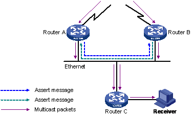
Figure 7-2 Diagram for assert mechanism
When Router A and Router B receive a multicast packet sent from the multicast source S, they will all forward the multicast packet to the Ethernet. In this case, the downstream node Router C will receive two copies of the same multicast packet.
7.1.3 Introduction to PIM-SM
Protocol independent multicast sparse mode (PIM-SM) is a sparse mode multicast protocol. It is generally used in the following occasions where:
l Group members are sparsely distributed
l The range is wide
l Large scaled networks
In PIM-SM, all hosts do not receive multicast packets by default. Multicast packets are forwarded to the hosts which need multicast packets explicitly.
In order that the receiver can receive the multicast data streams of the specific IGMP groups, PIM-SM adopts rendezvous points (RP) to forward multicast information to all PIM-SM routers with receivers. RP is adopted in multicast forwarding. As a result, the network bandwidth that the data packets and control messages occupy is reduced, and the processing overhead of the router is also reduced.
In the receiving end, the router connected to the receiver sends a join message to the RP corresponding to the multicast group. The join message reaches the root (namely, RP) after passing each router. The passed paths become the branches of the rendezvous point tree (RPT).
If the sending end wants to send data to a multicast group, the first hop router will send a register message to the RP. When the register message reaches RP, the source tree establishing is triggered. Then the multicast source sends the data to RP. When the data reaches RP, the multicast packets are replicated and sent to the receiver over the RPT. Replication happens only in the branch of the RPT. The procedure is repeated automatically until the multicast packets reach the receiver.
7.1.4 Work Mechanism of PIM-SM
The working procedure of PIM-SM is:
l Neighbor discovery
l DR election
l RP discovery
l RPT establishing
l Multicast source registration
l RPT-to-SPT switchover
I. Neighbor discovery
The neighbor discovery mechanism is the same as described in PIM-DM. It is also implemented through Hello messages sent between each router.
II. DR election
With the help of Hello messages, DR can be elected for the shared network, such as Ethernet. DR will be the unique multicast information forwarder in the network. In either the network connected to the multicast source S or the network connected to the receiver, DR must be elected only if the network is a shared network. The DR in the receiving end sends join messages to RP and the DR in the multicast source side sends register messages to the RP, as shown in Figure 7-3:
Figure 7-3 Diagram for DR election
Each router on the shared network sends Hello messages with the DR priority option to each other. The router with the highest DR priority is elected as the DR in the network. If the priority is the same, the router with the highest IP address is elected as the DR. When the DR fails, the received Hello messages will time out. A new DR election procedure will be triggered among neighboring routers.
& Note:
In a PIM-SM network, the DR mainly serves as the querier of IGMPv1.
III. RP discovery
The RP is the core router in a PIM-SM domain. The shared tree established based on the multicast routing information is rooted in RP. There is a mapping relationship between the multicast group and RP. One multicast group is mapped to only one RP, and multiple multicast groups can be mapped to the same RP.
In a small and simple network, there is only little multicast information. One RP is enough for information forwarding. In this case, you can statically specify the position of RP in each router in the SM domain.
However, a PIM-SM network is of very large scale generally. The RP forwards a lot of multicast information. In order to reduce the workload of the RP and optimize the topology of the shared tree, different multicast groups must have different RPs. In this case, RPs must be elected dynamically through the Bootstrap mechanism and Bootstrap router (BSR) must be configured.
The BSR is the core management device in a PIM-SM network. The BSR is responsible for:
l Collecting the Advertisement messages sent by the Candidate-RP (C-RP) in the network.
l Selecting part of the C-RP information to constitute the RP-set, namely, the mapping database between the multicast group and RP.
l Advertising the RP-set to the whole network in order that all the routers (including the DR) in the network know the position of the RP.
One or more candidate BSRs must be configured in a PIM domain. Through the auto-election, the candidate BSRs elect a BSR which is responsible for collecting and advertising RP information. The auto-election among candidate BSRs is described in the following section:
l Specify a PIM-SM-enabled interface when configuring a router as a candidate BSR.
l Each candidate BSR considers itself as the BSR of the PIM-SM network and uses the IP address of the specified interface as the BSR address to send Bootstrap messages.
l When the candidate BSR receives Bootstrap messages from other routers, it will compare the BSR address in each received Bootstrap message with its own BSR address in priority and IP address. When the priority is the same, the candidate BSR with a higher IP address is considered to be better. If the former is better, the candidate BSR will replace its own BSR address with the new BSR address and does not consider itself as BSR any more. Otherwise, the candidate BSR will keep its own BSR address and continue to consider itself as BSR.
The positions of RPs and BSRs in the network are as shown in Figure 7-4:
Figure 7-4 Diagram for the communication between RPs and BSRs
Only one BSR can be elected in a network or management domain, while multiple candidate BSRs (C-BSR) can be configured. In this case, once the BSR fails, other C-BSRs can elect a new BSR through auto-election. Thus, the service is prevented from being interrupted.
In the same way, multiple C-RPs can be configured in a PIM-SM domain, the RP corresponding to each multicast group is figured out through the BSR mechanism.
IV. RPT establishing
Assume the receiver hosts are User B, and User C. When a receiver host joins in a multicast group G, it will inform the leaf router directly connected to the host through IGMP messages. Thus the leaf router masters the receiver information of the multicast group G, and then the leaf router will send join messages to the upstream nodes in the direction of RP, as shown in Figure 7-5:
Figure 7-5 Diagram for RPT establishing in PIM-SM
Each router on the path from the leaf router to the RP will generate (*, G) entries in the forwarding table. The routers on the path form a branch of the RPT. A (*, G) entry represents the information from any source to the multicast group G. The RP is the root of the RPT and the receivers are leaves of the RPT.
When the packet from the multicast source S to the multicast group G passes by the RP, the packet will reach the leaf router and receiver host over the established path in the RPT.
When the receiver is not interested in the multicast information any more, the multicast router nearest to the receiver will send a prune messages to the RP hop by hop in the direction reverse to the RPT. When the first upstream router receives the prune message, it will remove the links to the downstream router from the interface list and check whether it has the receivers interested in the multicast information. If not, the upstream router will continue to forward the prune message to upstream routers.
V. Multicast source registration
In order to inform the RP about the existence of multicast source S, when multicast source S sends a multicast packet to the multicast group G, the router directly connected to S will encapsulate the received packet into a register message and unicast it to the corresponding RP, as shown in Figure 7-6:
Figure 7-6 Diagram for SPT establishing in PIM-SM
When the RP receives the register message from S, it will decapsulate the register message and forward the multicast data to the receiver over the RPT, and on the other hand, it will send a (S, G) join message to S hop by hop. The passed routers constitute a branch of the SPT. The multicast source S is the root of the SPT and the RP is the destination of the SPT.
The multicast data sent by the multicast source S will reach the RP over the established SPT, and then the RP will forward the multicast data along the established RPT.
VI. RPT-to-SPT switchover
When the multicast router nearest to the receiver detects that the rate of multicast packets from the RP to the multicast group G exceeds the threshold value, it will send an (S, G) join message to the upper-layer router in the direction of the multicast source S. The join message reaches the router nearest to the multicast source (namely, the first hop router) hop by hop and all the passed routers have the (S, G) entry. As a result, a branch of the SPT is established.
Then, the last hop router sends a prune message with the RP bit to the RP hop by hop. When the RP receives the message, it will reversely forward the prune message to the multicast source. Thus, the multicast data stream is switched from the RPT to the SPT.
After the RPT-to-SPT switchover, the multicast data will be sent from the multicast source S to the receiver directly. Through the RPT-to-SPT switchover, the PIM-SM can establish an SPT in a more economical way than PIM-DM.
The related threshold value is not set on S7500 series Ethernet switches. When the switch receives multicast data forwarded over the RPT, it will update the incoming interface automatically and sends a prune message to the RP.
7.2 Common PIM Configuration
Complete the following tasks to configure PIM:
|
Task |
Remarks |
|
Required |
|
|
Optional |
|
|
Optional |
|
|
Optional |
7.2.1 Enabling PIM-DM (PIM-SM) on the Interface
Follow these steps to enable PIM-DM (PIM-SM) on the interface:
|
To do... |
Use the command... |
Remarks |
|
Enter system view |
system-view |
— |
|
Enable the multicast routing protocol |
multicast routing-enable |
Required |
|
Enter VLAN interface view |
interface Vlan-interface interface-number |
— |
|
Enable PIM-DM/PIM-SM |
pim dm / pim sm |
Optional Configure the PIM protocol type on the interface. |
7.2.2 Configuring the Interval of Sending Hello Messages
PIM-DM must be enabled on each interface. After the configuration, PIM-DM will send PIM Hello messages periodically and process protocol messages that the PIM neighbors send.
Follow these steps to configure the interval of sending Hello messages:
|
To do... |
Use the command... |
Remarks |
|
Enter system view |
system-view |
— |
|
Enable the multicast routing protocol |
multicast routing-enable |
Required |
|
Enter VLAN interface view |
interface Vlan-interface interface-number |
— |
|
Enable PIM-DM/PIM-SM |
pim dm / pim sm |
Required Configure the PIM protocol type on the interface. |
|
Configure the interval of sending Hello messages |
pim timer hello seconds |
Required The interval of sending Hello messages is 30 seconds. |
![]() Caution:
Caution:
l When PIM-DM is enabled on an interface, PIM-SM cannot be enabled on the interface any more, and vice versa.
l When PIM-DM is enabled on an interface of the switch, only PIM-DM can be enabled on the other interfaces of the switch, and vice versa.
7.2.3 Configuring PIM Neighbors
In order to prevent plenty of PIM neighbors from using out the memory of the router, which may result in router failure, you can limit the number of PIM neighbors on the router interface. However, the total number of PIM neighbors of a router is defined by the system, and you cannot modify it by using commands.
You can configure basic ACL 2000 to 2999 (refer to the part about ACL in this manual). Only the filtered Layer 3 switches (routers) cam serve as the PIM neighbors of the current interface.
Follow these steps to configure PIM neighbors:
|
To do... |
Use the command... |
Remarks |
|
Enter system view |
system-view |
— |
|
Enable the multicast routing protocol |
multicast routing-enable |
Required |
|
Enter VLAN interface view |
interface Vlan-interface interface-number |
— |
|
Enable PIM-DM/PIM-SM |
pim dm / pim sm |
Required Configure the PIM protocol type on the interface. |
|
Configure limit on the number of PIM neighbors |
pim neighbor-limit limit |
Optional By default, the upper limit on the number of PIM neighbors on an interface is 128. |
|
Configure the filtering policy for PIM neighbors |
pim neighbor-policy acl-number |
Optional l You can configure to filter the IP addresses of some multicast groups in ACL. l By default, the filtering policy for neighbors cannot be enabled on an interface. |
![]() Caution:
Caution:
If the number of existing PIM neighbors exceeds the user-defined limit, the existing PIM neighbors will not be removed.
7.2.4 Clearing PIM Relevant Entries
You can execute the reset command in user view to clear the related statistics about multicast PIM.
Follow these steps to clear PIM relevant entries:
|
To do... |
Use the command... |
Remarks |
|
Clear the PIM route entries |
reset pim routing-table { all | { group-address [ mask group-mask | mask-length group-mask-length ] | source-address [ mask source-mask | mask-length source-mask-length ] | { incoming-interface { interface-type interface-number | null } } } * } |
Perform the configuration in user view. |
|
Clear PIM neighbors |
reset pim neighbor { all | { neighbor-address | interface interface-type interface-number } * } |
Perform the configuration in user view. |
7.3 PIM-DM Configuration
Perform the following configuration to configure PIM-DM. When the router runs in a PIM-DM domain, you are recommended to enable PIM-DM on all the interfaces of non-boarder routers.
7.3.1 Configuring Filtering Policies for Multicast Source/Group
Follow these steps to configure filtering policies for multicast source/group:
|
To do... |
Use the command... |
Remarks |
|
Enter system view |
system-view |
— |
|
Enable the multicast routing protocol |
multicast routing-enable |
Required |
|
Enter PIM view |
pim |
— |
|
Perform source/group filter on the received multicast packets |
source-policy acl-number |
Optional You can configure to filter the IP addresses of some multicast groups in an ACL. |
![]() Caution:
Caution:
l If you configure basic ACLs, the source address match is performed on all the received multicast packets. The packets failing to match are discarded.
l If you configure advanced ACLs, the source address and group address match are performed on all the received multicast packets. The packets failing to match are discarded.
7.4 PIM-SM Configuration
Complete the following tasks to configure PIM-SM:
|
Task |
Remarks |
|
Optional |
|
|
Optional |
|
|
Optional |
|
|
Optional |
7.4.1 Configuring Filtering Policies for Multicast Source/Group
For the configuration of filtering policies for multicast source/group, refer to Configuring Filtering Policies for Multicast Source/Group.
7.4.2 Configuring BSR/RP
Follow these steps to configure BSR/RP:
|
To do... |
Use the command... |
Remarks |
|
Enter system view |
system-view |
— |
|
Enable the multicast routing protocol |
multicast routing-enable |
Required |
|
Enter PIM view |
pim |
— |
|
Configure candidate BSRs |
c-bsr interface-type interface-number hash-mask-len [ priority ] |
Optional By default, candidate BSRs are not set for the switch and the value of priority is 0. |
|
Configure candidate RPs |
c-rp interface-type interface-number [ group-policy acl-number | priority priority ]* |
Optional l You can configure to filter the IP addresses of some multicast groups in an ACL. l By default, candidate RPs are not set for the switch and the value of priority is 0. |
|
Configure static RPs |
static-rp rp-address [ acl-number ] |
Optional l You can configure to filter the IP addresses of some multicast groups in ACL. l By default, static RPs are not set for the switch. |
|
Limit the range of valid BSRs |
bsr-policy acl-number |
Optional l You can configure to filter the IP addresses of some multicast groups in an ACL. l By default, the range of valid BSRs is not set for the switch. |
|
Limit the range of valid C-RPs |
crp-policy acl-number |
Optional l You can configure to filter the IP addresses of some multicast groups in an ACL. l By default, the range of valid C-RPs is not set for the switch. |
![]() Caution:
Caution:
l Only one candidate BSR can be configured on a Layer 3 switch. The BSR configuration on another interface will replace the former configuration.
l You are recommended to configure both the candidate BSR and candidate RPs on a Layer 3 switch in the backbone network.
l If the range of multicast groups that the RP serves is not specified when the RP is configured, the RP serves all multicast groups. Otherwise, the RP serves the multicast groups within the specified range.
l You can configure basic ACLs to filter related multicast IP addresses and control the range of multicast groups that the RP serves.
l If you use static RPs, all routers in the PIM domain must adopt the same configuration.
l If the configured static RP address is the address of an up interface on the local switch, the switch will serve as a static RP.
l Static RPs do not take effect until the RP generated by the BSR mechanism takes effect.
l The PIM protocol need not be enabled on the interfaces of static RPs.
l The limit on the range of valid BSRs is to prevent the valid BSRs in the network being replaced maliciously. The other BSR information except the range will not be received by the Layer 3 switch, and thus the security of BSRs in the network is protected.
l The limit on the range of C-RPs is to avoid C-RP cheating. You can limit the range of valid C-RPs and limit the range of multicast groups that each C-RP serves.
7.4.3 Configuring PIM-SM Domain Boundary
Follow these steps to configure PIM-SM domain boundary:
|
To do... |
Use the command... |
Remarks |
|
Enter system view |
system-view |
— |
|
Enable the multicast routing protocol |
multicast routing-enable |
Required |
|
Enter VLAN interface view |
interface Vlan-interface interface-number |
— |
|
Enable PIM-SM |
pim sm |
Required Configure the PIM protocol type on the interface. |
|
Configure PIM-SM domain boundary |
pim bsr-boundary |
Required By default, domain boundary is not set for the switch. |
![]() Caution:
Caution:
l When the PIM-SM domain boundary is set, Bootstrap messages cannot pass the boundary in any direction. In this way, PIM-SM domains are divided.
l When this feature is configured, Bootstrap messages cannot pass the boundary. However, the other PIM messages can pass the domain boundary. The network can be effectively divided into domains using different BSRs.
7.4.4 Configuring the RP to Filter Register Messages from the DR
Through the register message filtering mechanism in a PIM-SM network, you can determine which sources send packets to which groups on the RP, that is, the RP can filter the register messages from the DR and receive the specified messages only.
Follow these steps to configure the RP to filter the register messages from the DR:
|
To do... |
Use the command... |
Remarks |
|
Enter system view |
system-view |
— |
|
Enable the multicast routing protocol |
multicast routing-enable |
Enable the multicast routing protocol. |
|
Enter VLAN interface view |
interface Vlan-interface interface-number |
— |
|
Enable PIM-SM |
pim sm |
Required Configure the PIM protocol type on the interface. |
|
Quit VLAN view |
quit |
— |
|
Enter PIM view |
pim |
— |
|
Configure the RP to filter the register messages from the DR |
register-policy acl-number |
Required l You can configure to filter the IP addresses of some multicast groups in an ACL. l By default, the switch does not filter the register messages from the DR. |
![]() Caution:
Caution:
l If a (S, G) entry is denied in an ACL, or no operation on the entry is defined in the ACL, or no ACL is defined, the RP will send a register stop message to the DR to stop the registration process of the multicast data stream.
l Only the register messages matching the permit rule of the ACL can be accepted. When an invalid ACL is defined, the RP will reject all the register messages.
7.5 Displaying and Maintaining PIM
|
To do... |
Use the command... |
Remarks |
|
Display PIM multicast routing tables |
display pim routing-table [ { { *g [ group-address [ mask { mask-length | mask } ] ] | **rp [ rp-address [ mask { mask-length | mask } ] ] } | { group-address [ mask { mask-length | mask } ] | source-address [ mask { mask-length | mask } ] } * } | incoming-interface { interface-type interface-number | null } | { dense-mode | sparse-mode } ] * |
Available in any view |
|
Display the information about PIM interfaces |
display pim interface [ interface-type interface-number ] |
|
|
Display the information about PIM neighbor routers |
display pim neighbor [ interface interface-type interface-number ] |
|
|
Display BSR information |
display pim bsr-info |
|
|
Display RP information |
display pim rp-info [ group-address ] |
7.6 PIM Configuration Examples
7.6.1 PIM-DM Configuration Example
I. Network requirements
Lanswitch1 is connected to the multicast source through VLAN-interface 10, to Lanswitch2 through VLAN-interface 11 and to Lanswitch3 through VLAN-interface 12. Through PIM-DM, multicast is implemented among Receiver 1, Receiver 2 and the multicast source.
II. Network diagram
Figure 7-7 Network diagram for PIM-DM configuration
III. Configuration procedure
Only the configuration procedure on Lanswitch1 is listed. The configuration procedures of Lanswitch2 and Lanswitch3 are similar to that of Lanswitch1.
# Enable the multicast routing protocol.
<H3C> system-view
[H3C] multicast routing-enable
# Enable IGMP and PIM-DM on the interfaces.
[H3C] vlan 10
[H3C-vlan10] port Ethernet 2/0/2 to Ethernet 2/0/3
[H3C-vlan10] quit
[H3C] vlan 11
[H3C-vlan11] port Ethernet 2/0/4 to Ethernet 2/0/5
[H3C-vlan11] quit
[H3C] vlan 12
[H3C-vlan12] port Ethernet 2/0/6 to Ethernet 2/0/7
[H3C-vlan12] quit
[H3C] interface Vlan-interface 10
[H3C-Vlan-interface10] ip address 1.1.1.1 255.255.0.0
[H3C-Vlan-interface10] igmp enable
[H3C-Vlan-interface10] pim dm
[H3C-Vlan-interface10] quit
[H3C] interface Vlan-interface 11
[H3C-Vlan-interface11] ip address 2.2.2.2 255.255.0.0
[H3C-Vlan-interface11] pim dm
[H3C-Vlan-interface11] quit
[H3C] interface Vlan-interface 12
[H3C-Vlan-interface12] ip address 3.3.3.3 255.255.0.0
[H3C-Vlan-interface12] pim dm
7.6.2 PIM-SM Configuration Example
I. Network requirements
All Ethernet switches are reachable for each other in the practical network.
l LS_A is connected to LS_B through VLAN-interface 10, to Host A through VLAN-interface 11 and to LS_C through VLAN-interface 12.
l LS_B is connected to LS_A through VLAN-interface 10, to LS_C through VLAN-interface 11 and to LS_D through VLAN-interface 12.
l LS_C is connected to Host B through VLAN-interface 10, to LS_B through VLAN-interface 11 and to LS_A through VLAN-interface 12.
Host A is the receiver of the multicast group whose multicast IP address is 225.0.0.1. Host B begins to send data to the destination 225.0.0.1 and LS_A receives the multicast data from Host B through LS_B.
II. Network diagram
Figure 7-8 Network diagram for PIM-SM configuration
III. Configuration procedure
1) Configure LS_A
# Enable PIM-SM.
<H3C> system-view
[H3C] multicast routing-enable
[H3C] vlan 10
[H3C-vlan10] port Ethernet 2/0/2 to Ethernet 2/0/3
[H3C-vlan10] quit
[H3C] interface Vlan-interface 10
[H3C-Vlan-interface10] igmp enable
[H3C-Vlan-interface10] pim sm
[H3C-Vlan-interface10] quit
[H3C] vlan 11
[H3C-vlan11] port Ethernet 2/0/4 to Ethernet 2/0/5
[H3C-vlan11] quit
[H3C] interface Vlan-interface 11
[H3C-Vlan-interface11] pim sm
[H3C-Vlan-interface11] quit
[H3C] vlan 12
[H3C-vlan12] port Ethernet 2/0/6 to Ethernet 2/0/7
[H3C-vlan12] quit
[H3C] interface Vlan-interface 12
[H3C-Vlan-interface12] pim sm
[H3C-Vlan-interface12] quit
2) Configure LS_B
# Enable PIM-SM.
<H3C> system-view
[H3C] multicast routing-enable
[H3C] vlan 10
[H3C-vlan10] port Ethernet 2/0/2 to Ethernet 2/0/3
[H3C-vlan10] quit
[H3C] interface Vlan-interface 10
[H3C-Vlan-interface10] pim sm
[H3C-Vlan-interface10] quit
[H3C] vlan 11
[H3C-vlan11] port Ethernet 2/0/4 to Ethernet 2/0/5
[H3C-vlan11] quit
[H3C] interface Vlan-interface 11
[H3C-Vlan-interface11] pim sm
[H3C-Vlan-interface11] quit
[H3C] vlan 12
[H3C-vlan12] port Ethernet 2/0/6 to Ethernet 2/0/7
[H3C-vlan12] quit
[H3C] interface Vlan-interface 12
[H3C-Vlan-interface12] pim sm
[H3C-Vlan-interface12] quit
# Configure candidate BSRs.
[H3C] pim
[H3C-pim] c-bsr Vlan-interface 10 30 2
# Configure candidate RPs.
[H3C] acl number 2000
[H3C-acl-basic-2000] rule permit source 225.0.0.0 0.255.255.255
[H3C] pim
[H3C-pim] c-rp Vlan-interface 10 group-policy 2000
# Configure PIM domain boundary.
[H3C] interface Vlan-interface 12
[H3C-Vlan-interface12] pim bsr-boundary
When VLAN-interface 12 is configured as the PIM domain boundary, LS_D cannot receive BSR information from LS_B any more, that is, LS_D is excluded from the PIM domain.
3) Configure LS_C
# Enable PIM-SM.
<H3C> system-view
[H3C] multicast routing-enable
[H3C] vlan 10
[H3C-vlan10] port Ethernet 2/0/2 to Ethernet 2/0/3
[H3C-vlan10] quit
[H3C] interface Vlan-interface 10
[H3C-Vlan-interface10] igmp enable
[H3C-Vlan-interface10] igmp enable
[H3C-Vlan-interface10] pim sm
[H3C-Vlan-interface10] quit
[H3C] vlan 11
[H3C-vlan11] port Ethernet 2/0/4 to Ethernet 2/0/5
[H3C-vlan11] quit
[H3C] interface Vlan-interface 11
[H3C-Vlan-interface11] pim sm
[H3C-Vlan-interface11] quit
[H3C] vlan 12
[H3C-vlan12] port Ethernet 2/0/6 to Ethernet 2/0/7
[H3C-vlan12] quit
[H3C] interface Vlan-interface 12
[H3C-Vlan-interface12] pim sm
[H3C-Vlan-interface12] quit
7.7 Troubleshooting PIM
Symptom 1: The router cannot set up multicast routing tables correctly.
Solution: You can troubleshoot PIM according to the following procedure.
Make sure that the unicast routing is right before troubleshooting PIM.
l Because PIM-SM needs the support of RPs and BSRs, you must execute the display pim bsr-info command to see whether BSR information exists. If not, you must check whether there are unicast routes to the BSR. Then use the display pim rp-info command to check whether the RP information is right. If no RP information exists, you must check whether there are unicast routes to the RP.
l Use the display pim neighbor command to check whether the neighboring relationship is correctly established.