- Table of Contents
-
- H3C S7500 Series Operation Manual(Release 3100 Series)-(V1.04)
- 00-1Cover
- 00-2Overview
- 01-CLI Configuration
- 02-Login Configuration
- 03-Configuration File Management Configuration
- 04-VLAN Configuration
- 05-Extended VLAN Application Configuration
- 06-IP Address-IP Performance-IPX Configuration
- 07-GVRP Configuration
- 08-QinQ Configuration
- 09-Port Basic Configuration
- 10-Link Aggregation Configuration
- 11-Port Isolation Configuration
- 12-Port Binding Configuration
- 13-DLDP Configuration
- 14-MAC Address Table Configuration
- 15-MSTP Configuration
- 16-Routing Protocol Configuration
- 17-Multicast Configuration
- 18-802.1x Configuration
- 19-AAA-RADIUS-HWTACACS-EAD Configuration
- 20-Traffic Accounting Configuration
- 21-VRRP-HA Configuration
- 22-ARP Configuration
- 23-DHCP Configuration
- 24-ACL Configuration
- 25-QoS Configuration
- 26-Mirroring Configuration
- 27-Cluster Configuration
- 28-PoE Configuration
- 29-UDP-Helper Configuration
- 30-SNMP-RMON Configuration
- 31-NTP Configuration
- 32-SSH Terminal Service Configuration
- 33-File System Management Configuration
- 34-FTP and TFTP Configuration
- 35-Information Center Configuration
- 36-DNS Configuration
- 37-System Maintenance and Debugging Configuration
- 38-HWPing Configuration
- 39-RRPP Configuration
- 40-NAT-Netstream-Policy Routing Configuration
- 41-Telnet Protection Configuration
- 42-Hardware-Dependent Software Configuration
- Related Documents
-
| Title | Size | Download |
|---|---|---|
| 26-Mirroring Configuration | 217 KB |
Table of Contents
Chapter 1 Mirroring Configuration
1.1.4 Remote Traffic Mirroring
1.2 Mirroring Supported by S7500
1.3.1 Configuring Port Mirroring
1.3.2 Configuring Remote Port Mirroring
1.3.3 Configuring Traffic Mirroring
1.3.4 Configuring Remote Traffic Mirroring
Chapter 1 Mirroring Configuration
When configuring mirroring, go to these sections for information you are interested in:
l Overview
l Mirroring Supported by S7500
1.1 Overview
Mirroring refers to the process of copying packets that meet the specified rules to a destination port. Generally, a destination port is connected to a data detect device, through which users can analyze the mirrored packets for monitoring and troubleshooting the network.
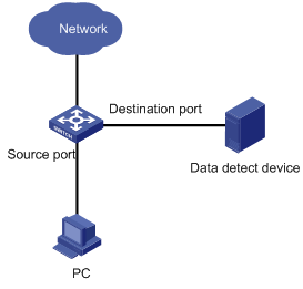
1.1.1 Port Mirroring
Port mirroring refers to the process of copying the packets received or sent by the specified port to the specified local port.
1.1.2 Remote Port Mirroring
Remote port mirroring eliminates the limitation that the source port and the destination port must be located on the same switch. This feature makes it possible for the source port and the destination port to be located on different devices in the network, and facilitates the network administrator to manage remote switches.
The implementation of remote port mirroring is illustrated in the following figure:
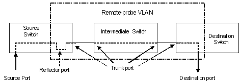
Figure 1-2 Remote port mirroring implementation
With the remote port mirroring function enabled, a switch plays one of the following three roles.
l Source switch: The switch to which the monitored port belongs. The source switch copies the mirrored traffic flows to the remote-probe VLAN, and then through Layer 2 forwarding, the mirrored flows are sent to an intermediate switch or destination switch.
l Intermediate switch: Switches between the source switch and destination switch on the network. An intermediate switch forwards mirrored flows to the next intermediate switch or the destination switch. No intermediate switch is required if a direct connection exists between the source and destination switches.
l Destination switch: The switch to which the destination port for remote mirroring belongs. It forwards mirrored flows it received from the remote-probe VLAN to the monitoring device through the destination port.
& Note:
When a switch acts as an intermediate switch or destination switch for the remote mirroring, to realize the data mirroring successfully, you are recommended to configure redirection on the inbound interface and redirect all the packets in the remote-probe VLAN to the corresponding outbound interface (intermediate switch) or mirroring destination port (destination switch).
Table 1-1 describes how the ports on various switches are involved in the mirroring operation.
Table 1-1 Ports involved in the mirroring operation
|
Switch |
Ports involved |
Function |
|
Source switch |
Source port |
Port to be mirrored; copies user data packets to the specified reflector port through local port mirroring. There can be more than one source port. |
|
Reflector port |
Receives user data packets that are mirrored on a local port. |
|
|
Trunk port |
Sends mirrored packets to the intermediate switch or the destination switch. |
|
|
Intermediate switch |
Trunk port |
Sends mirrored packets to the destination switch. Two Trunk ports are necessary for the intermediate switch to be connected to devices that are connected to the source switch and the destination switch. |
|
Destination switch |
Trunk port |
Receives remote mirrored packets. |
|
Destination port |
Monitors remote mirrored packets |
To implement remote port mirroring, you need to define a special VLAN, called remote-probe VLAN, on all the three types of switches. In this VLAN, no normal data but only mirrored packets are transmitted. All mirrored packets will be transferred to the specified port of the destination switch from the source switch through this VLAN. Thus, the destination switch can monitor the port packets sent from the remote ports of the source switch. Remote-probe VLAN requires that:
l You are recommended to configure all ports connecting the devices in remote-probe VLAN as Trunk ports.
l The default VLAN and management VLAN cannot be configured as remote-probe VLAN.
l Required configurations are performed to ensure Layer 2 connectivity between the source and destination switches over the remote-probe VLAN.
![]() Caution:
Caution:
To ensure the normal packet mirroring, you are not recommended to perform any of the following operations on the remote-probe VLAN:
l Configuring a source port to the remote-probe VLAN that is used by the local mirroring group;
l Configuring a Layer 3 interface for the remote-probe VLAN;
l Running other protocol packets, or bearing other service packets;
l Using remote-probe VLAN as a special type of VLAN, such as voice VLAN or protocol VLAN;
l Configuring other VLAN-related functions.
1.1.3 Traffic Mirroring
Traffic mirroring maps traffic flows that match specific ACL rules to the specified local port for packet analysis and monitoring. Before configuring traffic mirroring, you need to define ACL rules required for flow identification.
1.1.4 Remote Traffic Mirroring
Remote traffic mirroring copies traffic flows that match specific ACLs to the reflector port of the specified mirroring group. Then, after corresponding configurations of remote port mirroring, the matching traffic flows are finally copied to the specified ports of other switches. Similar to configuring local traffic mirroring, you need to define ACL rules required for flow identification first. Otherwise, you need to complete all configurations of remote port mirroring (except the configuration of source port for mirroring).
1.2 Mirroring Supported by S7500
Table 1-2 Mirroring functions supported by S7500 and related commands
|
Function |
Specifications |
Related command |
Related section |
|
Mirroring |
Support port mirroring |
mirroring-group mirroring-group mirroring-port mirroring-group monitor-port |
|
|
Support remote port mirroring |
mirroring-group mirroring-group mirroring-port mirroring-group monitor-port mirroring-group reflector-port mirroring-group remote-probe vlan remote-probe vlan enable |
||
|
Support traffic mirroring |
mirroring-group mirroring-group mirroring-port mirroring-group monitor-port mirrored-to |
||
|
Support remote traffic mirroring |
mirroring-group mirroring-group monitor-port mirroring-group reflector-port mirroring-group remote-probe vlan remote-probe vlan enable mirrored-to |
1.3 Mirroring Configuration
For mirroring features, see section Overview.
1.3.1 Configuring Port Mirroring
I. Configuration prerequisites
l The source port is specified and whether the packets to be mirrored are inbound or outbound is specified.
l The destination port is specified.
II. Configuring port mirroring in Ethernet port view
|
To do… |
Use the command… |
Remarks |
|
Enter system view |
system-view |
— |
|
Create a port mirroring group |
mirroring-group group-id local |
Required |
|
Enter Ethernet port view of the destination port |
interface interface-type interface-number |
— |
|
Define the current port as the destination port |
mirroring-group group-id monitor-port |
Required LACP and STP must be disabled on the destination port |
|
Exit current view |
quit |
— |
|
Enter Ethernet port view of the source port |
interface interface-type interface-number |
— |
|
Configure the source port and specify the direction of the packets to be mirrored |
mirroring-group group-id mirroring-port { both | inbound | outbound } |
Required |
|
Display parameter settings of the mirroring |
display mirroring-group { all | local } |
Required This command can be executed in any view. |
III. Configuring port mirroring in system view
|
To do… |
Use the command… |
Remarks |
|
Enter system view |
system-view |
— |
|
Create a port mirroring group |
mirroring-group group-id local |
Required |
|
Configure the destination port |
mirroring-group group-id monitor-port monitor-port |
Required LACP and STP must be disabled on the destination port. |
|
Configure the source port and specify the direction of the packets to be mirrored |
mirroring-group group-id mirroring-port mirroring-port-list { both | inbound | outbound } |
Required |
|
Display parameter settings of the mirroring |
display mirroring-group { all | local } |
Optional This command can be executed in any view. |
IV. Configuration Example
l The source port is GigabitEthernet 2/0/1. Mirror all packets received and sent via this port.
l The destination port is GigabitEthernet 2/0/4.
1) Configuration procedure 1:
<H3C> system-view
[H3C] mirroring-group 1 local
[H3C] interface GigabitEthernet 2/0/4
[H3C-GigabitEthernet2/0/4] mirroring-group 1 monitor-port
[H3C-GigabitEthernet2/0/4] quit
[H3C] interface GigabitEthernet 2/0/1
[H3C-GigabitEthernet2/0/1] mirroring-group 1 mirroring-port both
2) Configuration procedure 2:
<H3C> system-view
[H3C] mirroring-group 1 local
[H3C] mirroring-group 1 monitor-port GigabitEthernet 2/0/4
[H3C] mirroring-group 1 mirroring-port GigabitEthernet 2/0/1 both
1.3.2 Configuring Remote Port Mirroring
I. Configuration prerequisites
l The source switch, intermediate switch, and the destination switch have been determined.
l The source port, the reflector port, the destination port, and the remote-probe VLAN have been determined.
l Required configurations are performed to ensure Layer 2 connectivity between the source and destination switches over the remote-probe VLAN.
l The direction of the packets to be monitored has been determined.
l The remote-probe VLAN is enabled.
II. Configuring remote port mirroring on the source switch
|
To do… |
Use the command… |
Remarks |
|
Enter system view |
system-view |
— |
|
Create a VLAN and enter its VLAN view |
vlan vlan-id |
vlan-id is the ID of the destination remote-probe VLAN. |
|
Define the current VLAN as a remote-probe VLAN |
remote-probe vlan enable |
Required |
|
Exit current view |
quit |
— |
|
Enter port view of ports that connected to the intermediate switch or destination switch |
interface interface-type interface-number |
— |
|
Configure the current port as a trunk port |
port link-type trunk |
Required By default, the type of the port is access. |
|
Configure Trunk port to permit packets from the remote-probe VLAN |
port trunk permit vlan remote-probe-vlan-id |
Required This setting is required for source switch ports that connected with the intermediate switch or destination switch. |
|
Exit current view |
quit |
— |
|
Configure a remote source mirroring group |
mirroring-group group-id remote-source |
Required |
|
Configure a source port for remote mirroring |
mirroring-group group-id mirroring-port mirroring-port-list { both | inbound | outbound } |
Required |
|
Configure a remote reflector port |
mirroring-group group-id reflector-port reflector-port |
Required The remote reflector port must be of the Access type. LACP and STP must be disabled on this port. After a port is configured as a reflector port, the switch does not allow you to perform any of the following configurations: l Changing the port type and its default VLAN ID l Add it to another VLAN |
|
Configure the remote-probe VLAN for the remote source mirroring group |
mirroring-group group-id remote-probe vlan remote-probe-vlan-id |
Required |
|
Display the configuration of the remote source mirroring group |
display mirroring-group remote-source |
Optional This command can be executed in any view. |
& Note:
l To mirror tagged packets, you need to configure VLAN VPN on the reflector port.
l The reflector port cannot forward traffics as a normal port. Therefore, it is recommended that you use a idle and in-down-state port as the reflector port, and be careful to not add other settings on this port.
l Be sure not to configure a port used to connect the intermediate and destination switches as the mirroring source port. Otherwise traffic disorder may occur in the network.
III. Configuring remote port mirroring on the intermediate switch
|
To do… |
Use the command… |
Remarks |
|
Enter system view |
system-view |
— |
|
Create a remote-probe VLAN and enter VLAN view |
vlan vlan-id |
vlan-id is the ID of the remote-probe VLAN. |
|
Define the current VLAN as a remote-probe VLAN |
remote-probe vlan enable |
Required |
|
Exit current view |
quit |
— |
|
Enter Ethernet port view of the port through which the intermediate switch is connected to the source switch, destination switch or another intermediate switch |
interface interface-type interface-number |
— |
|
Configure the current port as a trunk port |
port link-type trunk |
Required By default, the type of the port is access. |
|
Configure Trunk port to permit packets from the remote-probe VLAN |
port trunk permit vlan remote-probe-vlan-id |
Required This configuration is necessary for ports on the intermediate switch that are connected to the source switch or the destination switch. |
& Note:
When a switch acts as a remote port mirroring intermediate switch, to realize the data mirroring successfully, you are recommended to configure redirection on the inbound interface and redirect all the packets in the remote-probe VLAN to the corresponding outbound interface.
IV. Configuring remote port mirroring on the destination switch
|
To do… |
Use the command… |
Remarks |
|
Enter system view |
system-view |
— |
|
Create a remote-probe VLAN and enter VLAN view |
vlan vlan-id |
vlan-id is the ID of the remote-probe VLAN. |
|
Define the current VLAN as a remote-probe VLAN |
remote-probe vlan enable |
Required |
|
Exit the current view |
quit |
— |
|
Enter Ethernet port view of the port through which the destination switch is connected to the source switch or an intermediate switch |
interface interface-type interface-number |
— |
|
Configure the current port as a trunk port |
port link-type trunk |
Required By default, the type of the port is access. |
|
Configure Trunk port to permit packets from the remote-probe VLAN |
port trunk permit vlan remote-probe-vlan-id |
Required This configuration is necessary for ports through which the destination switch is connected to the source switch or an intermediate switch. |
|
Exit current view |
quit |
— |
|
Configure the remote destination mirroring group |
mirroring-group group-id remote-destination |
Required |
|
Configure the destination port for remote mirroring |
mirroring-group group-id monitor-port monitor-port |
Required The destination port for remote mirroring must be of the Access type. LACP and STP must be disabled on this port. After you configure a port as the destination port for remote mirroring, the switch does not allow you to change the port type or default VLAN ID of the port. |
|
Configure the remote-probe VLAN for the remote destination mirroring group |
mirroring-group group-id remote-probe vlan remote-probe-vlan-id |
Required |
|
Display the configuration of the remote destination mirroring group |
display mirroring-group remote-destination |
Optional This command can be executed in any view. |
& Note:
When a switch acts as a remote port mirroring destination switch, to realize the data mirroring successfully, you are recommended to configure redirection on the inbound interface and redirect all the packets in the remote-probe VLAN to the corresponding mirroring destination port.
V. Configuration example
1) Network requirements:
l Switch A is connected to the data detect device via GigabitEthernet 2/0/2.
l GigabitEthernet 2/0/1, the Trunk port of Switch A, is connected to GigabitEthernet 2/0/1, the Trunk port of Switch B.
l GigabitEthernet 2/0/2, the Trunk port of Switch B, is connected to GigabitEthernet 2/0/1, the Trunk port of Switch C.
l GigabitEthernet 2/0/2, the port of Switch C, is connected to PC 1.
The purpose is to monitor and analyze the packets sent to PC 1 via the data detect device.
To meet the requirement above by using the remote port mirroring function, perform the following configuration:
l Define VLAN 10 as remote-probe VLAN.
l Define Switch A as the destination switch; configure GigabitEthernet 2/0/2, the port that is connected to the data detect device, as the destination port for remote mirroring. Set GigabitEthernet 2/0/2 to an Access port, with STP and LACP functions disabled.
l Define Switch B as the intermediate switch.
l Define Switch C as the source switch, GigabitEthernet 2/0/2 as the source port for remote mirroring, and GigabitEthernet 2/0/3 as the reflector port. Set GigabitEthernet 2/0/3 to an Access port, with STP and LACP disabled.
2) Network diagram
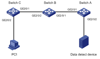
Figure 1-3 Network diagram for remote port mirroring configuration
3) Configuration procedure
# Configure Switch C.
<H3C> system-view
[H3C] vlan 10
[H3C-vlan10] remote-probe vlan enable
[H3C-vlan10] quit
[H3C] interface GigabitEthernet 2/0/1
[H3C-GigabitEthernet2/0/1] port link-type trunk
[H3C-GigabitEthernet2/0/1] port trunk permit vlan 10
[H3C-GigabitEthernet2/0/1] quit
[H3C] mirroring-group 1 remote-source
[H3C] mirroring-group 1 mirroring-port GigabitEthernet 2/0/2 inbound
[H3C] mirroring-group 1 reflector-port GigabitEthernet 2/0/3
[H3C] mirroring-group 1 remote-probe vlan 10
[H3C] display mirroring-group remote-source
mirroring-group 1:
type: remote-source
status: active
mirroring port:
GigabitEthernet2/0/2 inbound
reflector port: GigabitEthernet2/0/3
remote-probe vlan: 10
# Configure Switch B.
<H3C> system-view
[H3C] vlan 10
[H3C-vlan10] remote-probe vlan enable
[H3C-vlan10] quit
[H3C] interface GigabitEthernet 2/0/1
[H3C-GigabitEthernet2/0/1] port link-type trunk
[H3C-GigabitEthernet2/0/1] port trunk permit vlan 10
[H3C-GigabitEthernet2/0/1] quit
[H3C] interface GigabitEthernet 2/0/2
[H3C-GigabitEthernet2/0/2] port link-type trunk
[H3C-GigabitEthernet2/0/2] port trunk permit vlan 10
# Configure Switch A.
<H3C> system-view
[H3C] vlan 10
[H3C-vlan10] remote-probe vlan enable
[H3C-vlan10] quit
[H3C] interface GigabitEthernet 2/0/1
[H3C-GigabitEthernet2/0/1] port link-type trunk
[H3C-GigabitEthernet2/0/1] port trunk permit vlan 10
[H3C-GigabitEthernet2/0/1] quit
[H3C] mirroring-group 1 remote-destination
[H3C] mirroring-group 1 monitor-port GigabitEthernet 2/0/2
[H3C] mirroring-group 1 remote-probe vlan 10
[H3C] display mirroring-group remote-destination
mirroring-group 1:
type: remote-destination
status: active
monitor port: GigabitEthernet2/0/2
remote-probe vlan: 10
1.3.3 Configuring Traffic Mirroring
I. Configuration prerequisites
l ACLs for identifying traffics have been defined. For defining ACLs, see the description on the ACL module in this manual.
l The destination port has been defined.
l The port on which to perform traffic mirroring configuration and the direction of traffic mirroring has been determined.
II. Configuration procedure
|
To do… |
Use the command… |
Remarks |
|
Enter system view |
system-view |
— |
|
Create a mirroring group |
mirroring-group group-id local |
Required |
|
Define the destination port |
mirroring-group group-id monitor-port monitor-port |
Required LACP and STP cannot be enabled on the destination port. |
|
Enter Ethernet port view of the source port |
interface interface-type interface-number |
— |
|
Enter QoS view |
qos |
— |
|
Reference ACLs for identifying traffic flows and perform traffic mirroring for packets that match. |
mirrored-to inbound acl-rule [ system-index ] { interface interface-type interface-number | mirroring-group group-id } |
Required |
|
Display the parameter settings of traffic mirroring |
display qos-interface [ interface-type interface-number ] mirrored-to |
Optional These commands can be executed in any view. |
|
Display all QoS settings of a port |
display qos-interface [ interface-type interface-number ] all |
acl-rule: Applied ACL rules, which can be the combination of different types of ACL rules. The following table describes the ACL combinations.
Table 1-3 Combined application of ACLs on type A LPUs.
|
Combination mode |
Form of acl-rule |
|
Apply all rules in an IP type ACL |
ip-group { acl-number | acl-name } |
|
Apply one rule in an IP type ACL |
ip-group { acl-number | acl-name } rule rule-id |
|
Apply all rules in a link type ACL |
link-group { acl-number | acl-name } |
|
Apply one rule in a link type |
link-group { acl-number | acl-name } rule rule-id |
Table 1-4 Combined application of ACLs on LPUs other than type A.
|
Combination mode |
Form of acl-rule |
|
Apply all rules in an IP type ACL |
ip-group { acl-number | acl-name } |
|
Apply one rule in an IP type ACL |
ip-group { acl-number | acl-name } rule rule-id |
|
Apply all rules in a link type ACL |
link-group { acl-number | acl-name } |
|
Apply one rule in a link type |
link-group { acl-number | acl-name } rule rule-id |
|
Apply all rules in a user-defined ACL |
user-group { acl-number | acl-name } |
|
Apply one rule in a user-defined ACL |
user-group { acl-number | acl-name } rule rule-id |
|
Apply one rule in an IP type ACL and one rule in a Link type ACL simultaneously |
ip-group { acl-number | acl-name } rule rule-id link-group { acl-number | acl-name } rule rule-id |
& Note:
To define a destination port for mirroring, you can also enter the port view of the specified port directly to execute the mirroring-group group-id monitor-port command. Refer to corresponding command manual for detail.
III. Configuration example
1) Network requirements:
l GigabitEthernet 2/0/1 on the switch is connected to the 10.1.1.1/24 network segment.
l Mirror the packets from the 10.1.1.1/24 network segment to GigabitEthernet 2/0/4, the destination port.
2) Configuration procedure:
<H3C> system-view
[H3C] acl number 2000
[H3C-acl-basic-2000] rule permit source 10.1.1.1 0.0.0.255
[H3C-acl-basic-2000] rule deny source any
[H3C-acl-basic-2000] quit
[H3C] mirroring-group 3 local
[H3C] mirroring-group 3 monitor-port GigabitEthernet 2/0/4
[H3C] interface GigabitEthernet 2/0/1
[H3C-GigabitEthernet2/0/1] qos
[H3C-qosb-GigabitEthernet2/0/1] mirrored-to inbound ip-group 2000 interface GigabitEthernet 2/0/4
1.3.4 Configuring Remote Traffic Mirroring
I. Configuration prerequisites
l ACLs for identifying traffics have been defined. For defining ACLs, refer to the description on the ACL module in this manual.
l The source switch, intermediate switch and the destination switch have been specified.
l The reflector port, destination port for mirroring, and remote-probe VLAN have been specified.
l Required configurations are performed to ensure Layer 2 connectivity between the source and destination switches over the remote-probe VLAN.
l The direction of traffic packets to be monitored has been determined.
l The remote-probe VLAN has been enabled.
II. Configuring the source switch
|
To do… |
Use the command… |
Remarks |
|
Enter system view |
system-view |
— |
|
Create a VLAN and enter the VLAN view |
vlan vlan-id |
The vlan-id is the ID of the remote-probe VLAN to be defined. |
|
Define the current VLAN as the remote-probe VLAN |
remote-probe vlan enable |
Required |
|
Quit from the current view |
quit |
— |
|
Enter port view of the port connected with an intermediate switch or a destination switch |
interface interface-type interface-number |
— |
|
Configure the current port as a trunk port |
port link-type trunk |
Required By default, the type of the port is access. |
|
Configure the trunk port to permit the packets from the remote-probe VLAN to pass by. |
port trunk permit vlan remote-probe-vlan-id |
Required This configuration is required on the source switch ports that connect with the intermediate switch and the destination switch must be configured so. |
|
Quit from the current view |
quit |
— |
|
Configure the remote source mirroring group |
mirroring-group group-id remote-source |
Required |
|
Configure the remote reflector port |
mirroring-group group-id reflector-port reflector-port |
Required The remote reflector port must be Access port and LACP and STP must be disabled on the remote reflector port. After a port is configured as reflector port, you can neither change the port type and the default VLAN ID nor add the reflector port to other VLANs. |
|
Configure the remote-probe VLAN of the remote source mirroring group |
mirroring-group group-id remote-probe vlan remote-probe-vlan-id |
Required |
|
Ether Ethernet port view of the source port |
interface interface-type interface-number |
— |
|
Enter QoS view |
qos |
— |
|
Reference ACLs for identifying traffic flows and perform traffic mirroring for packets that match. |
mirrored-to inbound acl-rule [ system-index ] { interface interface-type interface-number reflector | mirroring-group group-id } |
Required |
|
Display configuration of the remote source mirroring group |
display mirroring-group remote-source |
Optional You can execute the display command in any view. |
|
Display the parameter settings of traffic mirroring |
display qos-interface [ interface-type interface-number ] mirrored-to |
|
|
Display all QoS settings of a port |
display qos-interface [ interface-type interface-number ] all |
acl-rule: Applied ACL rules, which can be the combination of different types of ACL rules. For the ACL combinations of the type A LPUs, refer to Table 1-3, and for the ACL combinations of LPUs other than type A, refer to Table 1-4.
& Note:
l If you want to mirror the tagged packets, you need to configure VLAN VPN on the reflector port.
l For the reflector port can not forward traffic as a normal port does, you are recommended to configure the port that is not in use to be the reflector port and not to perform other configurations on this port.
III. Configuring the intermediate switch
The configuration of remote traffic mirroring on the intermediate switch is the same as that of remote port mirroring on the intermediate switch. Refer to Configuring remote port mirroring on the intermediate switch.
IV. Configuring the destination switch
The configuration of remote traffic mirroring on the destination switch is the same as that of remote port mirroring on the destination switch. Refer to Configuring remote port mirroring on the destination switch.
V. Configuration example
1) Network requirements:
l Switch A is connected to the data detect device through GigabitEthernet 2/0/2.
l GigabitEthernet 2/0/1, the Trunk port of Switch A, is connected to GigabitEthernet 2/0/1, the Trunk port of Switch B.
l GigabitEthernet 2/0/2, the Trunk port of Switch B, is connected to GigabitEthernet 2/0/1, the Trunk port of Switch C.
l GigabitEthernet 2/0/2, the port of Switch C, is connected to the 10.1.1.1/24 network segment.
Use the remote traffic mirroring function to mirror the packets from the 10.1.1.1/24 network segment to GigabitEthernet 2/0/2, the port of Switch A, so that the data detect device can monitor the traffic:
l Define VLAN10 as remote-probe VLAN.
l Define Switch A as the destination switch; configure GigabitEthernet 2/0/2, the port that is connected to the data detect device, as the destination port for remote mirroring. Set GigabitEthernet 2/0/2 to an Access port, with STP and LACP functions disabled.
l Define Switch B as the intermediate switch.
l Define Switch C as the source switch, GigabitEthernet 2/0/3 as the reflector port. Set GigabitEthernet 2/0/3 to an Access port, with STP and LACP disabled. Configure the traffic mirroring function on GigabitEthernet 2/0/2.
2) Network diagram
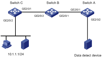
Figure 1-4 Network diagram for remote traffic mirroring
3) Configuration procedure
# Configure Switch A.
<H3C> system-view
[H3C] vlan 10
[H3C-vlan10] remote-probe vlan enable
[H3C-vlan10] quit
[H3C] interface GigabitEthernet 2/0/1
[H3C-GigabitEthernet2/0/1] port link-type trunk
[H3C-GigabitEthernet2/0/1] port trunk permit vlan 10
[H3C-GigabitEthernet2/0/1] quit
[H3C] mirroring-group 1 remote-destination
[H3C] mirroring-group 1 monitor-port GigabitEthernet 2/0/2
[H3C] mirroring-group 1 remote-probe vlan 10
[H3C] display mirroring-group remote-destination
mirroring-group 1:
type: remote-destination
status: active
monitor port: GigabitEthernet2/0/2
remote-probe vlan: 10
# Configure Switch B
<H3C> system-view
[H3C] vlan 10
[H3C-vlan10] remote-probe vlan enable
[H3C-vlan10] quit
[H3C] interface GigabitEthernet 2/0/1
[H3C-GigabitEthernet2/0/1] port link-type trunk
[H3C-GigabitEthernet2/0/1] port trunk permit vlan 10
[H3C-GigabitEthernet2/0/1] quit
[H3C] interface GigabitEthernet 2/0/2
[H3C-GigabitEthernet2/0/2] port link-type trunk
[H3C-GigabitEthernet2/0/2] port trunk permit vlan 10
# Configure Switch C
<H3C> system-view
[H3C] acl number 2000
[H3C-acl-basic-2000] rule permit source 10.1.1.1 0.0.0.255
[H3C-acl-basic-2000] rule deny source any
[H3C-acl-basic-2000] quit
[H3C] vlan 10
[H3C-vlan10] remote-probe vlan enable
[H3C-vlan10] quit
[H3C] interface GigabitEthernet 2/0/1
[H3C-GigabitEthernet2/0/1] port link-type trunk
[H3C-GigabitEthernet2/0/1] port trunk permit vlan 10
[H3C-GigabitEthernet2/0/1] quit
[H3C] mirroring-group 1 remote-source
[H3C] mirroring-group 1 reflector-port GigabitEthernet 2/0/3
[H3C] mirroring-group 1 remote-probe vlan 10
[H3C] interface GigabitEthernet 2/0/2
[H3C-GigabitEthernet2/0/2] qos
[H3C-qosb-GigabitEthernet2/0/2] mirrored-to inbound ip-group 2000 interface GigabitEthernet 2/0/3 reflector
[H3C-qosb-GigabitEthernet2/0/2] display qos-interface GigabitEthernet2/0/2 mirrored-to
GigabitEthernet2/0/2: mirrored-to
Inbound:
Matches: Acl 2000 rule 0 running
Mirrored to: mirroring-group 1