- Table of Contents
-
- H3C S7500 Series Operation Manual(Release 3100 Series)-(V1.04)
- 00-1Cover
- 00-2Overview
- 01-CLI Configuration
- 02-Login Configuration
- 03-Configuration File Management Configuration
- 04-VLAN Configuration
- 05-Extended VLAN Application Configuration
- 06-IP Address-IP Performance-IPX Configuration
- 07-GVRP Configuration
- 08-QinQ Configuration
- 09-Port Basic Configuration
- 10-Link Aggregation Configuration
- 11-Port Isolation Configuration
- 12-Port Binding Configuration
- 13-DLDP Configuration
- 14-MAC Address Table Configuration
- 15-MSTP Configuration
- 16-Routing Protocol Configuration
- 17-Multicast Configuration
- 18-802.1x Configuration
- 19-AAA-RADIUS-HWTACACS-EAD Configuration
- 20-Traffic Accounting Configuration
- 21-VRRP-HA Configuration
- 22-ARP Configuration
- 23-DHCP Configuration
- 24-ACL Configuration
- 25-QoS Configuration
- 26-Mirroring Configuration
- 27-Cluster Configuration
- 28-PoE Configuration
- 29-UDP-Helper Configuration
- 30-SNMP-RMON Configuration
- 31-NTP Configuration
- 32-SSH Terminal Service Configuration
- 33-File System Management Configuration
- 34-FTP and TFTP Configuration
- 35-Information Center Configuration
- 36-DNS Configuration
- 37-System Maintenance and Debugging Configuration
- 38-HWPing Configuration
- 39-RRPP Configuration
- 40-NAT-Netstream-Policy Routing Configuration
- 41-Telnet Protection Configuration
- 42-Hardware-Dependent Software Configuration
- Related Documents
-
| Title | Size | Download |
|---|---|---|
| 05-Extended VLAN Application Configuration | 315 KB |
Table of Contents
Chapter 1 Voice VLAN Configuration
1.2.1 Configuration Prerequisites
1.2.2 Setting Voice VLAN Mode on a Port to Automatic Mode
1.2.3 Setting Voice VLAN Mode on a Port to Manual Mode
1.3 Displaying Voice VLAN Configuration
1.4 Voice VLAN Configuration Examples
1.4.1 Configuring Automatic Voice VLAN Mode
1.4.2 Configuring Manual Voice VLAN Mode
Chapter 2 Isolate-User-VLAN Configuration
2.1 Isolate-User-VLAN Overview
2.1.1 Introduction to Isolate-User-VLAN
2.1.2 Isolate-User-VLAN Packets Forwarding Process
2.2 Isolate-User-VLAN Configuration
2.2.1 Isolate-User-VLAN Configuration Task List
2.2.2 Configuring Isolate-User-VLAN
2.2.3 Configuring Secondary VLAN
2.2.4 Adding Ports to Isolate-User-VLAN and Secondary VLAN
2.2.5 Configuring Mapping Between Isolate-User-VLAN and Secondary VLAN
2.3 Displaying Isolate-User-VLAN Configuration
2.4 Isolate-User-VLAN Configuration Example
3.2.1 Super VLAN Configuration Task List
3.2.2 Configuring a Super VLAN
3.2.4 Configuring the Mapping between a Super VLAN and Sub VLANs
3.2.5 Configuring Super VLAN to Support DHCP Relay
3.4 Super VLAN Configuration Examples
3.4.1 Super VLAN Configuration Example
3.4.2 Super VLAN Supporting DHCP Relay Example
Chapter 1 Voice VLAN Configuration
When configuring voice VLAN, go to these sections for information you are interested in:
l Displaying Voice VLAN Configuration
l Voice VLAN Configuration Examples
1.1 Voice VLAN Overview
Voice VLANs are VLANs configured specially for voice data stream. By adding the ports that connect voice devices to voice VLANs, you can configure quality of service (QoS) attributes for voice data, increasing the transmission priority of voice data stream and ensuring voice quality.
S7500 series Ethernet switches determine whether a received packet is a voice packet by checking its source MAC address. Packets containing source MAC addresses that comply with the voice device organizationally unique identifier (OUI) addresses are regarded as voice traffic and are transmitted in the voice VLAN.
You can configure OUI addresses in advance or use the default OUI addresses.
& Note:
An OUI address is a globally unique identifier assigned to a vendor by IEEE. You can determine which vendor a device belongs to according to the OUI address which forms the first 24 bits of a MAC address.
The following table shows the five default OUI addresses of a switch.
Table 1-1 Default OUI addresses preset by the switch
|
Number |
OUI Address |
Vendor |
|
1 |
00e0-bb00-0000 |
3com phone |
|
2 |
0003-6b00-0000 |
Cisco phone |
|
3 |
00e0-7500-0000 |
Polycom phone |
|
4 |
00d0-1e00-0000 |
Pingtel phone |
|
5 |
000f-e200-0000 |
H3C Aolynk phone |
There are two voice VLAN modes on a port: automatic and manual. You can configure the voice VLAN mode of a port according to data stream passing through the port.
l In automatic voice VLAN mode: In automatic voice VLAN mode, the system identifies the source MAC address contained in the untagged packet sent when the IP phone is powered on and matches it against the OUI addresses. If a match is found, the system will automatically add the port into the voice VLAN. An aging time can be configured for the voice VLAN. The system will remove a port from the voice VLAN if no voice packet is received from it after the aging time. The adding and deleting of ports are automatically realized by the system.
l In manual voice VLAN mode: administrators need to execute related commands to add an IP phone access port to the voice VLAN or remove an IP phone access port from the voice VLAN.
For the tagged packets sent by IP voice devices, they are processed in the same way in either of the above two modes: forwarded within corresponding VLAN according to their VLAN ID in the tags.
Voice VLAN packets can be forwarded by trunk ports and hybrid ports in voice VLAN. You can enable a trunk port or a hybrid port belonging to other VLANs to forward voice and service packets simultaneously by enabling the voice VLAN function for it.
As multiple types of IP voice devices exist, you need to match the voice VLAN mode of a port with the type of voice stream sent by IP voice devices, as listed in Table 1-2.
Table 1-2 Matching relationship between port modes and voice stream types
|
Port voice VLAN mode |
Voice stream type |
Port type |
Supported or not |
|
Automatic mode |
Tagged voice stream |
Access |
Not supported |
|
Trunk |
Supported Make sure the default VLAN of the IP phone access port exists and is not the voice VLAN. And the IP phone access port permits the packets of the default VLAN to pass. |
||
|
Hybrid |
Supported Make sure the default VLAN of the IP phone access port exists and is in the list of the tagged VLANs whose packets are permitted by the access port. |
||
|
Untagged voice stream |
Access |
Not supported, because the default VLAN of the IP phone access port must be the voice VLAN and the IP phone access port should be in the voice VLAN. Doing so, you add the port to the voice VLAN manually. |
|
|
Trunk |
|||
|
Hybrid |
|||
|
Manual mode |
Tagged voice stream |
Access |
Not supported |
|
Trunk |
Supported Make sure the default VLAN of the IP phone access port exists and is not the voice VLAN. And the access port permits the packets of the default VLAN. |
||
|
Hybrid |
Supported Make sure the default VLAN of the IP phone access port exists and is in the list of the tagged VLANs whose packets are permitted by the access port. |
||
|
Untagged voice stream |
Access |
Supported Make sure the default VLAN of the IP phone access port is the voice VLAN. |
|
|
Trunk |
Supported Make sure the default VLAN of the port is the voice VLAN and the port permits the packets of the default VLAN. |
||
|
Hybrid |
Supported Make sure the default VLAN of the port is a voice VLAN and is in the list of untagged VLANs whose packets are permitted by the port. |
![]() Caution:
Caution:
l If the voice traffic sent by an IP voice device is tagged and the access port has 802.1x authentication and guest VLAN enabled, assign different VLAN IDs for the voice VLAN, the default VLAN of the access port, and the 802.1x guest VLAN.
l If the voice traffic sent by the IP voice device is untagged, to realize the voice VLAN feature, the default VLAN of the IP phone access port can only be configured as the voice VLAN. Note that at this time 802.1 x authentication function cannot be realized.
1.2 Voice VLAN Configuration
1.2.1 Configuration Prerequisites
l Create the corresponding VLAN before configuring the voice VLAN.
l VLAN 1 is the default VLAN and needs not to be created. But VLAN 1 does not support the voice VLAN function.
1.2.2 Setting Voice VLAN Mode on a Port to Automatic Mode
Follow these steps to set the voice VLAN mode on a port to automatic:
|
To do… |
Use the command… |
Remarks |
|
Enter system view |
system-view |
— |
|
Enter Ethernet port view |
interface interface-type interface-number |
Required |
|
Enable the voice VLAN function for the port |
voice vlan enable |
Required By default, the voice VLAN function is disabled. |
|
Set the voice VLAN mode on the port to automatic mode |
voice vlan mode auto |
Optional The default voice VLAN mode on the port is automatic. |
|
Return to system view |
quit |
— |
|
Set an OUI address that can be identified by the voice VLAN |
voice vlan mac-address oui mask oui-mask [ description text ] |
Optional By default, the switch uses the default OUI addresses to determine the voice stream. |
|
Enable the voice VLAN security mode |
voice vlan security enable |
Optional By default, the voice VLAN security mode on the port is enabled. |
|
Set the aging time for the voice VLAN |
voice vlan aging minutes |
Optional The default aging time is 1,440 minutes. |
|
Enable the voice VLAN function globally |
voice vlan vlan-id enable |
Required |
& Note:
If the voice VLAN of a device suffers a restart of the device during normal operation, in order to make the established voice connection works normally, the system will add the port whose voice VLAN mode is configured as automatic into the voice VLAN automatically after the restart, instead of waiting for the trigger of voice traffic.
1.2.3 Setting Voice VLAN Mode on a Port to Manual Mode
Follow these steps to set the voice VLAN mode on a port to manual mode:
|
To do… |
Use the command… |
Remarks |
||
|
Enter system view |
system-view |
— |
||
|
Enter port view |
interface interface-type interface-number |
Required |
||
|
Enable the voice VLAN function for the port |
voice vlan enable |
Required By default, the voice VLAN function is disabled on a port. |
||
|
Set voice VLAN mode on the port to manual mode |
undo voice vlan mode auto |
Required The default voice VLAN mode on a port is automatic. |
||
|
Return to system view |
quit |
— |
||
|
Add a manual mode port to the voice VLAN |
Access port |
Enter VLAN view |
vlan vlan-id |
Required |
|
Add the port to the VLAN |
port interface-list |
|||
|
Trunk or Hybrid port |
Enter port view |
interface interface-type interface-number |
||
|
Add the port to the voice VLAN |
port trunk permit vlan vlan-id port hybrid vlan vlan-id { tagged | untagged } |
|||
|
Configure the voice VLAN to be the default VLAN of the port |
port trunk pvid vlan vlan-id port hybrid pvid vlan vlan-id |
Optional Refer to Table 1-2 to determine whether or not this operation is needed. |
||
|
Return to system view |
quit |
— |
||
|
Set an OUI address that can be identified by the voice VLAN |
voice vlan mac-address oui mask oui-mask [ description text ] |
Optional If you do not set the address, the default OUI addresses will be used. |
||
|
Enable the voice VLAN security mode |
voice vlan security enable |
Optional By default, the voice VLAN security mode on a port is enabled. |
||
|
Set aging time for the voice VLAN |
voice vlan aging minutes |
Optional The default aging time is 1,440 minutes. |
||
|
Enable the voice VLAN function globally |
voice vlan vlan-id enable |
Required |
||
![]() Caution:
Caution:
l You can enable the voice VLAN feature for only one VLAN at a moment.
l A port that has the link aggregation control protocol (LACP) enabled cannot have the voice VLAN feature enabled at the same time.
l A port that has the QinQ or RRPP enabled cannot have the voice VLAN feature enabled at the same time.
l Voice VLAN function can be effective only for the static VLAN. Once a dynamic VLAN is enabled with voice VLAN function, it automatically becomes a static VLAN.
l When the voice VLAN mode on a port is the security mode, the device only permits packets whose source addresses are the voice OUI addresses that can be identified. Packets whose source addresses cannot be identified, including certain authentication packets (such as 802.1x authentication packets), will be dropped. So, do not transmit both voice data and service data in the voice VLAN. If you have to do so, make sure the voice VLAN security mode is disabled.
1.3 Displaying Voice VLAN Configuration
|
To do… |
Use the command… |
Remarks |
|
Display the voice VLAN configuration status |
display voice vlan status |
Available in any view. |
|
Display the currently valid OUI addresses |
display voice vlan oui |
|
|
Display the ports operating in the voice VLAN |
display vlan vlan-id |
1.4 Voice VLAN Configuration Examples
1.4.1 Configuring Automatic Voice VLAN Mode
I. Network requirements
l Create VLAN 2 and configure it as the voice VLAN.
l Configure Ethernet 1/0/1 as a Trunk port, with VLAN 6 as the default VLAN of the port.
l Ethernet 1/0/1 can be added to/removed from the voice VLAN automatically according to the type of the data stream that reaches the port.
II. Configuration procedure
# Create VLAN 2.
<H3C> system-view
[H3C] vlan 2
# Configure Ethernet 1/0/1 to be a Trunk port, with VLAN 6 as its default VLAN.
[H3C-vlan2] quit
[H3C] interface Ethernet 1/0/1
[H3C-Ethernet1/0/1] port link-type trunk
[H3C-Ethernet1/0/1] port trunk pvid vlan 6
# Enable the voice VLAN function for the port and set the voice VLAN mode on the port to automatic mode.
[H3C-Ethernet1/0/1] voice vlan enable
[H3C-Ethernet1/0/1] voice vlan mode auto
# Enable the voice VLAN function globally.
[H3C-Ethernet1/0/1] quit
[H3C] voice vlan 2 enable
1.4.2 Configuring Manual Voice VLAN Mode
I. Network requirements
l Create VLAN 3 and configure it as the voice VLAN.
l Configure Ethernet 1/0/1 as a Trunk port and can be added to/removed from the voice VLAN manually.
l Configure the OUI address to be 0011-2200-0000, with the description string being test.
II. Configuration procedure
# Create VLAN 3.
<H3C> system-view
[H3C] vlan 3
[H3C-vlan3] quit
# Configure Ethernet 1/0/3 to be a Trunk port and add it to VLAN 3.
[H3C] interface Ethernet1/0/3
[H3C-Ethernet1/0/3] port link-type trunk
[H3C-Ethernet1/0/3] port trunk permit vlan 3
# Enable the voice VLAN function for the port and set the voice VLAN mode on the port to manual mode.
[H3C-Ethernet1/0/3] voice vlan enable
[H3C-Ethernet1/0/3] undo voice vlan mode auto
[H3C-Ethernet1/0/3] quit
# Specify an OUI address.
[H3C] voice vlan mac-address 0011-2200-0000 mask ffff-ff00-0000 description test
# Enable the voice VLAN function globally.
[H3C] voice vlan 3 enable
# Display voice VLAN-related configurations.
[H3C] display voice vlan status
Voice Vlan status: ENABLE
Voice Vlan ID: 3
Voice Vlan security mode: Security
Voice Vlan aging time: 1440 minutes
Current voice vlan enabled port mode:
PORT MODE
----------------------------------------
Ethernet1/0/3 MANUAL
# Remove Ethernet 1/0/3 from the voice VLAN.
[H3C] interface Ethernet1/0/3
[H3C-Ethernet1/0/3] undo port trunk permit vlan 3
Chapter 2 Isolate-User-VLAN Configuration
When configuring isolate-user-VLAN, go to these sections for information you are interested in:
l Isolate-User-VLAN Configuration
l Displaying Isolate-User-VLAN Configuration
l Isolate-User-VLAN Configuration Example
2.1 Isolate-User-VLAN Overview
2.1.1 Introduction to Isolate-User-VLAN
Isolate-user-VLAN is designed for saving VLAN resource by means of copying MAC address entries among the MAC address tables of VLANs, utilizing the feature that a Hybrid port can remove the VLAN tags of packets of multiple VLANs.
Isolate-user-VLAN adopts Layer 2 VLAN structure, and you need to configure two types of VLANs, isolate-user-VLAN and secondary VLAN.
An isolate-user-VLAN corresponds to multiple secondary VLANs. By configuring ports as Hybrid ports, you can make ports of all secondary VLANs and the uplink port of the switch all included in the isolate-user-VLAN. At the same time, you should configure that the uplink port removes the VLAN tags of all secondary VLAN packets when forwarding them.
In this case, for the upper layer switch, all the packets received from the lower stream are without VLAN tags. Therefore, the switch can reset the local VLAN structure to save VLAN resource without considering the VLAN configuration in the lower layer.
2.1.2 Isolate-User-VLAN Packets Forwarding Process
Figure 2-1 is the diagram for isolate-user-VLAN application. The following content describes the isolate-user-VLAN packets forwarding process based on this figure.
I. Configure Switch B
l Configure port Ethernet 1/0/4 as a Hybrid port, with the default VLAN ID being 3. This port belongs to both VLAN 3 and VLAN 5 (the isolate-user-VLAN), and performs untag operation (removing of VLAN tag) on packets coming from VLAN 3 and VLAN 5.
l Configure port Ethernet 1/0/1 as a Hybrid port, with the default VLAN ID being 5. This port belongs to both VLAN 3 and VLAN 5, and performs untag operation (removing of VLAN tag) on packets coming from VLAN 3 and VLAN 5.
II. Configure Switch A
To ensure that packets coming from Switch A can be forwarded by Switch B according to the VLAN configurations of the lower layer devices, you need to configure the port through which Switch A connects to Switch B to remove VLAN tags when Switch A sends packets to Switch B.
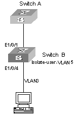
Figure 2-1 Diagram for isolate-user-VLAN application
III. Forward packets to Switch A
1) When packets sent by PC reaches Ethernet 1/0/4, the default VLAN ID, that is, the VLAN tag of VLAN 3 is automatically added to the packets.
2) Switch B learns the MAC address of the PC, and adds it to the MAC address forwarding table of VLAN 3, and at the same time copies the entry to the MAC address forwarding table of VLAN 5.
3) Because Ethernet 1/0/1 belongs to VLAN 3, Ethernet 1/0/1 can forward the packets from VLAN 3 and automatically removes the tag of VLAN 3, so that packets reaching Switch A is without the VLAN tag.
IV. Receive and forward packets from Switch A
1) When packets coming from Switch A (the packets are without VLAN tag through certain configuration) reach to port Ethernet 1/0/1 of Switch B, the packets are automatically added with default VLAN ID, that is, the tag of VLAN 5.
2) According to the MAC address forwarding table copied in the outbound process, the system will find the egress port being Ethernet 1/0/4.
3) Because Ethernet 1/0/4 belongs to VLAN 5, packets can pass through it normally, and at the same time, Ethernet 1/0/4 removes the VLAN tag of the packets. So that the PC receives packets without VLAN tag.
2.2 Isolate-User-VLAN Configuration
2.2.1 Isolate-User-VLAN Configuration Task List
Complete the following tasks to configure Isolate-user-VLAN:
|
Task |
Remarks |
|
Required |
|
|
Required |
|
|
Required |
|
|
Configuring Mapping Between Isolate-User-VLAN and Secondary VLAN |
Required |
2.2.2 Configuring Isolate-User-VLAN
Follow these steps to configure an isolate-user-VLAN:
|
To do… |
Use the command… |
Remarks |
|
Enter system view |
system-view |
— |
|
Create a VLAN and enter VLAN view |
vlan vlan-id |
Required |
|
Configure the VLAN as an isolate-user-VLAN |
isolate-user-vlan enable |
Required |
![]() Caution:
Caution:
l Multiple isolate-user-VLANs can be configured for a switch.
l With GVRP function enabled, a switch cannot be enabled with isolate-user-VLAN function.
l Isolate-user-VLANs do not forward multicast service data.
l You cannot enable both the isolate-user-VLAN function and super VLAN function for a VLAN. If a VLAN is specified as an isolate-user-VLAN or a secondary VLAN, you cannot configure it as a super VLAN or a sub VLAN additionally.
2.2.3 Configuring Secondary VLAN
Configuring a secondary VLAN is the same as configuring an ordinary VLAN.
Follow these steps to configure a secondary VLAN:
|
To do… |
Use the command… |
Remarks |
|
Enter system view |
system-view |
— |
|
Create a secondary VLAN |
vlan vlan-id |
Required |
2.2.4 Adding Ports to Isolate-User-VLAN and Secondary VLAN
In order to transmit packets normally, all ports included in the isolate-user-VLAN and the secondary VLANs must be Hybrid ports, and all ports must perform untag operation on all VLAN packets.
Follow these steps to add ports to isolate-user-VLAN and secondary VLANs and configure the ports to untag packets:
|
To do… |
Use the command… |
Remarks |
|
Enter system view |
system-view |
— |
|
Enter Ethernet port view |
interface interface-type interface-number |
— |
|
Configure the port as a hybrid port |
port link-type hybrid |
Required |
|
Add the port to the isolate-user-VLAN and the secondary VLAN |
port hyrbrid vlan vlan-id untagged |
Required |
|
Configure the default VLAN ID of the port |
port hybrid pvid vlan vlan-id |
Required |
![]() Caution:
Caution:
When you use the port hybrid pvid vlan command to configure the default VLAN ID for a port, note that you need to specify the vlan-id as a secondary VLAN for a downlink port and specify the vlan-id an isolate-user-VLAN for an uplink port.
2.2.5 Configuring Mapping Between Isolate-User-VLAN and Secondary VLAN
Follow these steps to establish mapping relationship between an isolate-user-VLAN and secondary VLANs:
|
To do… |
Use the command… |
Remarks |
|
Enter system view |
system-view |
— |
|
Configure the mapping relationship between an isolate-user-VLAN and secondary VLANs |
isolate-user-vlan vlan-id secondary vlan-list |
Required |
![]() Caution:
Caution:
An isolate-user-VLAN can establish mapping relationship with multiple secondary VLANs, however, a secondary VLAN can establish mapping relationship with only one isolate-user-VLAN.
2.3 Displaying Isolate-User-VLAN Configuration
|
To do… |
Use the command… |
Remarks |
|
Display the mapping relationship between the isolate-user-VLAN and the secondary VLANs |
display isolate-user-vlan [ vlan-id ] |
Available any view. |
2.4 Isolate-User-VLAN Configuration Example
2.4.1 Network requirements
l Switch A connects with Switch B and Switch C. For Switch A, packets from Switch B and Switch C are without VLAN tag, so that Switch A needs not to consider the VLAN configurations of the lower layer switches.
l VLAN 5 on Switch B is an isolate-user-VLAN which includes the uplink port Ethernet 1/0/1 and two secondary VLANs: VLAN 2 and VLAN 3. VLAN 3 includes port Ethernet 1/0/2, and VLAN 2 includes port Ethernet 1/0/5.
l VLAN 6 on Switch C is an isolate-user-VLAN which includes the uplink port Ethernet 1/0/1 and two secondary VLANs: VLAN 3 and VLAN 4. VLAN 3 includes port Ethernet 1/0/3, and VLAN 4 includes port Ethernet 1/0/4.
2.4.2 Network diagram
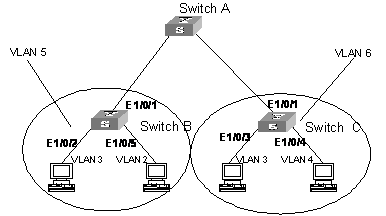
Figure 2-2 Diagram for isolate-user-VLAN configuration
2.4.3 Configuration procedure
l Configure Switch B
# Configure the isolate-user-VLAN
<SwitchB> system-view
[SwitchB] vlan 5
[SwitchB-vlan5] isolate-user-vlan enable
# Configure the secondary VLAN.
[SwitchB-vlan5] quit
[SwitchB] vlan 3
[SwitchB-vlan3] quit
[SwitchB] vlan 2
# Add port Ethernet 1/0/2 to the isolate-user-VLAN (VLAN 5) and the secondary VLAN (VLAN 3), and configure the port to untag the VLAN packets.
[SwitchB-vlan2] quit
[SwitchB] interface Ethernet 1/0/2
[SwitchB-Ethernet1/0/2] port link-type hybrid
[SwitchB-Ethernet1/0/2] port hybrid vlan 3 untagged
[SwitchB-Ethernet1/0/2] port hybrid vlan 5 untagged
[SwitchB-Ethernet1/0/2] port hybrid pvid vlan 3
# Add port Ethernet 1/0/5 to the isolate-user-VLAN (VLAN 5) and the secondary VLAN (VLAN 2), and configure the port to untag the VLAN packets.
[SwitchB-Ethernet1/0/2] quit
[SwitchB] interface Ethernet 1/0/5
[SwitchB-Ethernet1/0/5] port link-type hybrid
[SwitchB-Ethernet1/0/5] port hybrid vlan 2 untagged
[SwitchB-Ethernet1/0/5] port hybrid vlan 5 untagged
[SwitchB-Ethernet1/0/5] port hybrid pvid vlan 2
# Add port Ethernet 1/0/1 to the isolate-user-VLAN (VLAN 5) and the secondary VLANs (VLAN 2 and VLAN 3), and configure the port to untag the VLAN packets.
[SwitchB-Ethernet1/0/5] quit
[SwitchB] interface Ethernet 1/0/1
[SwitchB-Ethernet1/0/1] port link-type hybrid
[SwitchB-Ethernet1/0/1] port hybrid vlan 2 untagged
[SwitchB-Ethernet1/0/1] port hybrid vlan 3 untagged
[SwitchB-Ethernet1/0/1] port hybrid vlan 5 untagged
[SwitchB-Ethernet1/0/1] port hybrid pvid vlan 5
# Configure isolate-user-VLAN-to-secondary VLAN mapping.
[SwitchB-Ethernet1/0/1] quit
[SwitchB] isolate-user-vlan 5 secondary 2 to 3
l Configure Switch C
# Configure the isolate-user-VLAN
<SwitchC> system-view
[SwitchC] vlan 6
[SwitchC-vlan6] isolate-user-vlan enable
# Configure the secondary VLAN.
[SwitchC-vlan6] quit
[SwitchC] vlan 3
[SwitchC-vlan3] vlan 4
# Add port Ethernet 1/0/3 to the isolate-user-VLAN (VLAN 6) and the secondary VLAN (VLAN 3), and configure the port to untag the VLAN packets.
[SwitchC-vlan4] quit
[SwitchC] interface Ethernet 1/0/3
[SwitchC-Ethernet1/0/3] port link-type hybrid
[SwitchC-Ethernet1/0/3] port hybrid vlan 3 untagged
[SwitchC-Ethernet1/0/3] port hybrid vlan 6 untagged
[SwitchC-Ethernet1/0/3] port hybrid pvid vlan 3
# Add port Ethernet 1/0/4 to the isolate-user-VLAN (VLAN 6) and the secondary VLAN (VLAN 4), and configure the port to untag the VLAN packets.
[SwitchC-Ethernet1/0/3] quit
[SwitchC] interface Ethernet1/0/4
[SwitchC-Ethernet1/0/4] port link-type hybrid
[SwitchC-Ethernet1/0/4] port hybrid vlan 4 untagged
[SwitchC-Ethernet1/0/4] port hybrid vlan 6 untagged
[SwitchC-Ethernet1/0/4] port hybrid pvid vlan 4
# Add port Ethernet 1/0/1 to the isolate-user-VLAN (VLAN 6) and the secondary VLANs (VLAN 3 and VLAN 4), and configure the port to untag the VLAN packets.
[SwitchC-Ethernet1/0/4] quit
[SwitchC] interface Ethernet 1/0/1
[SwitchC-Ethernet1/0/1] port link-type hybrid
[SwitchC-Ethernet1/0/1] port hybrid vlan 3 untagged
[SwitchC-Ethernet1/0/1] port hybrid vlan 4 untagged
[SwitchC-Ethernet1/0/1] port hybrid vlan 6 untagged
[SwitchC-Ethernet1/0/1] port hybrid pvid vlan 6
# Configure isolate-user-VLAN-to-secondary VLAN mapping.
[SwitchC-Ethernet1/0/1] quit
[SwitchC] isolate-user-vlan 6 secondary 3 to 4
After the above configurations, Switch A can receive packets from Switch B and Switch C, and they are all packets without VLAN tag. VLAN 3 configured on Switch B and VLAN 3 configured on Switch C cannot communicate with each other because the packets from them are untagged before the packets reach Switch A. This makes the lower switches only own locally valid VLAN configuration. And in this way, the global VLAN resource is saved.
Chapter 3 Super VLAN
When configuring super VLAN, go to these sections for information you are interested in:
l Super VLAN Configuration Examples
& Note:
Only Salience III series engines support the super VLAN.
3.1 Super VLAN Overview
To save IP address resources, the super VLAN concept (also known as VLAN aggregation) was developed. Its principle is like this: a super VLAN may include multiple sub VLANs, with each as a broadcast domain. Layer 2 isolation is implemented between sub VLANs. The super VLAN, but not the sub VLAN, can be configured with a Layer 3 interface,.
When users in different sub VLANs want to communicate, they use the IP address of the Layer 3 interface of the super VLAN as their gateway address. IP address resources are saved since multiple sub VLANs share one IP address.
At the same time, in order to realize the Layer 3 connectivity between the sub VLANs and between the sub VLAN and other networks, proxy ARP is used. Proxy ARP enables Layer 3 connectivity between Layer 2 isolated ports by sending ARP request and processing response packets.
3.2 Super VLAN Configuration
3.2.1 Super VLAN Configuration Task List
Complete the following tasks to configure super VLAN:
|
Task |
Remarks |
|
Required |
|
|
Required |
|
|
Required |
|
|
Optional |
3.2.2 Configuring a Super VLAN
You can configure multiple super VLANs for a switch. You can use the following commands to specify a VLAN as a super VLAN. After a VLAN is configured as a super VLAN, the configuration of its VLAN interface and IP address is the same as the configuration for an ordinary VLAN.
Follow these steps to configure a VLAN as a super VLAN:
|
To do… |
Use the command… |
Remarks |
|
Enter system view |
system-view |
— |
|
Enter VLAN view |
vlan vlan-id |
— |
|
Configure the current VLAN as a super VLAN |
supervlan |
Required |
![]() Caution:
Caution:
l You can not configure a VLAN which includes Ethernet ports as a super VLAN; and after you configure a super VLAN, you cannot add any Ethernet port to it.
l When a VLAN is configured as a super VLAN, proxy ARP function is automatically enabled on the VLAN interface, and cannot be disabled.
3.2.3 Configuring a Sub VLAN
You can configure a sub VLAN just as configuring an ordinary VLAN. See the VLAN part of this manual for details. The configuration commands are shown in the following table.
Follow these steps to configure a sub VLAN:
|
To do… |
Use the command… |
Remarks |
|
Enter system view |
system-view |
— |
|
Create a sub VLAN |
vlan vlan-id |
Required |
|
Add Ethernet port(s) to the sub VLAN |
port interface-list |
Required |
![]() Caution:
Caution:
The port command is only used to add the Access ports to a sub VLAN. If you want to add a Trunk port or a Hybrid port to a sub VLAN, you need to execute the port trunk permit vlan command and the port hybrid vlan command in Ethernet port view. Refer to the Port part of the manual.
Note that you can add multiple ports (except the uplink port) for a sub VLAN.
3.2.4 Configuring the Mapping between a Super VLAN and Sub VLANs
Follow these steps to configure the mapping between a super VLAN and sub VLAN(s):
|
To do… |
Use the command… |
Remarks |
|
Enter system view |
system-view |
— |
|
Enter VLAN view of the super VLAN |
vlan vlan-id |
— |
|
Establish the mapping between the super VLAN and sub VLAN(s) |
port interface-list |
Required |
![]() Caution:
Caution:
l The sub VLANs must exist before you create mapping between the sub VLANs and the super VLAN.
l When you establish mapping between the super VLAN and the sub VLANs, if a VLAN interface is configured for the sub VLAN, the system will prompt you to delete the interface to establish the mapping successfully.
l After establishing the mapping between the sub VLANs and the super VLAN, you can still add (or remove) ports to (from) the sub VLANs.
l The system allows for up to 1024 sub VLANs.
3.2.5 Configuring Super VLAN to Support DHCP Relay
With DHCP relay function enabled on the VLAN interface of the super VLAN, the hosts of all sub VLANs that map with the super VLAN can dynamically obtain IP addresses from the outside networks.
With the DHCP relay function enabled on the VLAN interface of the super VLAN, the hosts of the sub VLANs that map the interface and the DHCP server in another network segment can forward the DHCP packets to each other, so as to assist the hosts in the sub VLANs to finish the dynamic configuration of IP address.
I. Configuration Prerequisites
l Configure a super VLAN and sub VLANs, and establish the mapping between the super VLAN the sub VLANs.
l Configure the IP address of the super VLAN to make the hosts in the sub VLANs be able to communicate with the outside network.
II. Configuration Procedure
|
To do… |
Use the command… |
Remarks |
|
Enter system view |
system-view |
— |
|
Enter VLAN interface view of the super VLAN |
interface Vlan-interface vlan-id |
— |
|
Configure the mapping between the interface and the DHCP server group |
dhcp-server groupNo |
Required By default, the VLAN interface does not establish mapping relationship with any DHCP server group. |
& Note:
l A super VLAN interface can only correspond to one DHCP server group.
l The last configuration will take effect if you execute the dhcp-server groupNo command for multiple times.
l The DHCP server group specified by groupNo of the dhcp-server groupNo command needs to be configured first by the dhcp-server ip command in system view. Refer to the DHCP part of the manual.
3.3 Displaying Super VLAN
|
To do… |
Use the command… |
Remarks |
|
Display the mapping between the super VLAN and the sub VLANs |
display supervlan [ supervlan-id ] |
Available in any view. |
3.4 Super VLAN Configuration Examples
3.4.1 Super VLAN Configuration Example
I. Network Requirements
Create super VLAN 10 and sub VLANs VLAN 2, VLAN 3, VLAN 5. Configure ports Ethernet 1/0/1 and Ethernet 1/0/2 to belong to VLAN 2, Ethernet 1/0/3 and Ethernet 1/0/4 to belong to VLAN 3, and Ethernet 1/0/5 and Ethernet 1/0/6 to belong to VLAN 5. Since Layer 2 isolation is implemented between VLANs, configure Layer 3 connectivity between sub VLANs, and all sub VLANs use the Layer 3 interface of the super VLAN (with the IP address being 10.110.1.1) as the gateway to communicate with the outside.
II. Network diagram
Omitted
III. Configuration procedure
# Create VLAN 10, and enable the super VLAN function on it.
<H3C> system-view
[H3C] vlan 10
[H3C-vlan10] supervlan
# Create VLAN 2, VLAN 3, and VLAN 5, and add corresponding ports to them.
[H3C-vlan10] vlan 2
[H3C-vlan2] port Ethernet 1/0/1 Ethernet 1/0/2
[H3C-vlan2] vlan 3
[H3C-vlan3] port Ethernet 1/0/3 Ethernet 1/0/4
[H3C-vlan3] vlan 5
[H3C-vlan5] port Ethernet 1/0/5 Ethernet 1/0/6
# Configure the mapping between the super VLAN and the sub VLANs.
[H3C-vlan5] vlan 10
[H3C-vlan10] subvlan 2 3 5
# Create the Layer 3 interface of the super VLAN, and configure an IP address for it.
[H3C-vlan10] interface Vlan-interface 10
[H3C-Vlan-interface10] ip address 10.110.1.1 255.255.255.0
& Note:
By default, the proxy ARP function is enabled on the VLAN interface of the super VLAN, and cannot be disabled.
3.4.2 Super VLAN Supporting DHCP Relay Example
I. Network requirements
l Create VLAN 6 and configure it as a super VLAN, and create VLAN 2 and VLAN 3 as the sub VLANs which map with VLAN 6.
l Configure the IP address of the VLAN 6 as 10.1.1.1, and the sub network mask as 255.255.255.0.
l Enable the DHCP relay function on the VLAN interface of VLAN 6, and establish the mapping between VLAN 6 and the remote DHCP server group 2 to make the hosts in VLAN 2 and VLAN 3 be able to dynamically obtain IP addresses from the DHCP server group 2.
II. Configuration Procedure
# Create VLAN 6, and configure it as a super VLAN.
<H3C> system-view
[H3C] vlan 6
[H3C-vlan6] supervlan
# Create VLAN 2 and VLAN 3 and establish the mapping between them and VLAN 6.
[H3C-vlan6] vlan 2
[H3C-vlan2] vlan 3
[H3C-vlan3] vlan 6
[H3C-vlan6] subvlan 2 3
# Create the VLAN interface of VLAN 6, and configure an IP address for it.
[H3C-vlan6] interface Vlan-interface 6
[H3C-Vlan-interface6] ip add 10.1.1.1 255.255.255.0
# Enable the DHCP relay function on the VLAN 6 interface, that is, establish the mapping between the interface and the DHCP server group 2.
[H3C-Vlan-interface6] dhcp-server 2