- Table of Contents
-
- H3C S7500 Series Operation Manual(Release 3100 Series)-(V1.04)
- 00-1Cover
- 00-2Overview
- 01-CLI Configuration
- 02-Login Configuration
- 03-Configuration File Management Configuration
- 04-VLAN Configuration
- 05-Extended VLAN Application Configuration
- 06-IP Address-IP Performance-IPX Configuration
- 07-GVRP Configuration
- 08-QinQ Configuration
- 09-Port Basic Configuration
- 10-Link Aggregation Configuration
- 11-Port Isolation Configuration
- 12-Port Binding Configuration
- 13-DLDP Configuration
- 14-MAC Address Table Configuration
- 15-MSTP Configuration
- 16-Routing Protocol Configuration
- 17-Multicast Configuration
- 18-802.1x Configuration
- 19-AAA-RADIUS-HWTACACS-EAD Configuration
- 20-Traffic Accounting Configuration
- 21-VRRP-HA Configuration
- 22-ARP Configuration
- 23-DHCP Configuration
- 24-ACL Configuration
- 25-QoS Configuration
- 26-Mirroring Configuration
- 27-Cluster Configuration
- 28-PoE Configuration
- 29-UDP-Helper Configuration
- 30-SNMP-RMON Configuration
- 31-NTP Configuration
- 32-SSH Terminal Service Configuration
- 33-File System Management Configuration
- 34-FTP and TFTP Configuration
- 35-Information Center Configuration
- 36-DNS Configuration
- 37-System Maintenance and Debugging Configuration
- 38-HWPing Configuration
- 39-RRPP Configuration
- 40-NAT-Netstream-Policy Routing Configuration
- 41-Telnet Protection Configuration
- 42-Hardware-Dependent Software Configuration
- Related Documents
-
| Title | Size | Download |
|---|---|---|
| 25-QoS Configuration | 468 KB |
Table of Contents
1.1.4 Priority of Protocol Packets
1.1.11 Traffic-based Traffic Statistics
1.2 QoS Supported by the S7500 Series Ethernet Switches
1.4 Configuring Priority According to Which a Packet is Put into an Output Queue
1.4.1 Setting the Priority According to Which a Packet is Put into an Output Queue
1.4.2 Configuring the 802.1p-Priority–to-Queue Mapping
1.5 Configuring Priority Marking
1.5.1 Configuration Prerequisites
1.6 Configuring Rate Limiting on a Port
1.6.1 Configuration Prerequisites
1.7.1 Configuration Prerequisites
1.7.2 Configuration Procedure of TP
1.8.1 Configuration Prerequisites
1.9 Configuring Queue Scheduling
1.9.1 Configuration Prerequisites
1.10 Configuring Congestion Avoidance
1.10.1 Configuration Prerequisites
1.10.2 Configuration Procedure
1.11 Configuring Traffic Statistics
1.11.1 Configuration Prerequisites
1.11.2 Configuration Procedure of Traffic Statistics
1.11.3 Clearing Traffic Statistics Information
1.12 Configuring Guaranteed Bandwidth
1.12.1 Configuration Prerequisites
1.12.2 Configuration Procedure
1.13.1 Configuration Procedure
1.13.2 Configuration Procedure
1.14 Configuring Traffic-Based Selective QinQ
1.14.1 Configuration Prerequisites
1.14.2 Configuration Procedure
1.15 QoS Configuration Examples
1.15.1 Configuration Example of TP and Rate Limiting on the Port
1.15.2 Configuration Example of Priority Marking
Chapter 1 QoS Configuration
& Note:
Type A line processing units (LPUs) include LS81FT48A, LS81FM24A, LS81FS24A, LS81GB8UA, LS81GT8UA, LS81FT48, LS81FM24, LS81FS24, LS81GB8U and LS81GT8U.
When performing QoS configuration, go to these sections for information you are interested in:
l Overview
l QoS Supported by the S7500 Series Ethernet Switches
l Configuring Priority According to Which a Packet is Put into an Output Queue
l Configuring Priority Marking
l Configuring Rate Limiting on a Port
l Configuring Queue Scheduling
l Configuring Congestion Avoidance
l Configuring Traffic Statistics
l Configuring Guaranteed Bandwidth
l Configuring Traffic-Based Selective QinQ
1.1 Overview
QoS (Quality of Service) is a concept generally existing in occasions with service supply and demand. It evaluates the ability to meet the need of the customers in service. Generally, the evaluation is not to grade precisely. Its purpose is to analyze the conditions when the service is the best and the conditions when the service still needs improvement and then to make improvements in the specified aspects.
1.1.1 Traffic
Traffic means service traffic, that is, all the packets passing the switch.
1.1.2 Traffic Classification
Traffic classification means to identify packets conforming to certain characters according to certain rules.
A classification rule is a filter rule configured to meet your management requirements. It can be very simple. For example, you can use a classification rule to identify traffic with different priorities according to the ToS field in the IP packet header. It can be very complicated too. For example, you can use a classification rule to identify the packets according to the combination of link layer (Layer 2), network layer (Layer 3) and transport layer (Layer 4) information including MAC addresses, IP protocols, source addresses, destination addresses, the port numbers of applications and so on.
1.1.3 Precedence
1) IP precedence, ToS precedence and DSCP precedence
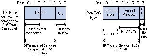
Figure 1-1 DS fields and TOS bytes
The ToS field in an IP header contains 8 bits:
l The high-order 3 bits represent IP precedence in the range of 0 to 7.
l Bit 3 to bit 6 represent ToS precedence in the range of 0 to 15.
l RFC2474 re-defines the ToS field in the IP packet header, which is called the DS field. The high-order 6 (bit 0 to bit 5) bits of the DS field represent DSCP precedence in the range of 0 to 63.The high-order 3 bits in DSCP precedence are class selector codepoints, bit 4 and bit 5 represent drop precedence, and bit 6 being zero indicates that the device sets the service class by using the DS model.
l The lower-order 2 bits (bit 6 and bit 7) are reserved bits.
The precedence values of an IP packet represent 8 different service classes.
Table 1-1 Description on IP Precedence
|
IP Precedence (decimal) |
IP Precedence (binary) |
Description |
|
0 |
000 |
routine |
|
1 |
001 |
priority |
|
2 |
010 |
immediate |
|
3 |
011 |
flash |
|
4 |
100 |
flash-override |
|
5 |
101 |
critical |
|
6 |
110 |
internet |
|
7 |
111 |
network |
The Diff-Serv network defines four traffic classes:
l Expedited Forwarding (EF) class: In this class, packets can be forwarded regardless of link sharing of the other traffic. The class is suitable for preferential services with low delay, low packet loss ratio, low jitter and guaranteed bandwidth (such as virtual leased line);
l Assured forwarding (AF) class: This class is further divided into four sub-classes (AF1/2/3/4) and a sub-class is further divided into three drop priorities, so the AF service level can be segmented. The QoS rank of the AF class traffic is lower than that of the EF class traffic;
l Class selector (CS) class: This class comes from the IP TOS field and includes 8 classes;
Table 1-2 Description on DSCP precedence
|
Keyword |
DSCP precedence (decimal) |
DSCP precedence (binary) |
|
ef |
46 |
101110 |
|
af11 |
10 |
001010 |
|
af12 |
12 |
001100 |
|
af13 |
14 |
001110 |
|
af21 |
18 |
010010 |
|
af22 |
20 |
010100 |
|
af23 |
22 |
010110 |
|
af31 |
26 |
011010 |
|
af32 |
28 |
011100 |
|
af33 |
30 |
011110 |
|
af41 |
34 |
100010 |
|
af42 |
36 |
100100 |
|
af43 |
38 |
100110 |
|
cs1 |
8 |
001000 |
|
cs2 |
16 |
010000 |
|
cs3 |
24 |
011000 |
|
cs4 |
32 |
100000 |
|
cs5 |
40 |
101000 |
|
cs6 |
48 |
110000 |
|
cs7 |
56 |
111000 |
|
default (be) |
0 |
000000 |
802.1p priority lies in a layer 2 frame headers and is applicable to occasions where layer 3 packet headers do not need analysis but QoS must be assured at layer 2.
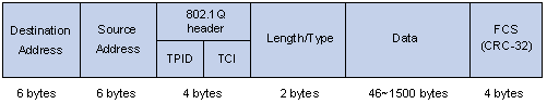
Figure 1-2 An Ethernet frame with a 802.1Q tag header
As shown in Figure 1-2, each host supporting 802.1Q protocol adds a 4-bit 802.1Q tag header after the source address field of the former Ethernet frame header when sending packets.
The 4-bit 802.1Q tag header contains a 2-bit tag protocol identifier (TPID) whose value is 8100 and a 2-bit tag control information (TCI). TPID is a new class defined by IEEE to identify a frame with an 802.1Q tag. Figure 1-3 describes the detailed contents of an 802.1Q tag header.
Figure 1-3 The contents of an 802.1Q tag header
In the figure above, the 3-bit priority field in the TCI filed is 802.1p priority in the range of 0 to 7.The 3 bits specify the precedence of the frame.8 classes of precedence are used to determine which frame is to be sent preferentially when congestion occurs on the switch.
Table 1-3 Description on 802.1p priority
|
CoS precedence (decimal) |
CoS precedence (binary) |
Description |
|
0 |
000 |
best-effort |
|
1 |
001 |
background |
|
2 |
010 |
spare |
|
3 |
011 |
excellent-effort |
|
4 |
100 |
controlled-load |
|
5 |
101 |
video |
|
6 |
110 |
voice |
|
7 |
111 |
network-management |
The precedence is called 802.1p priority because the related applications of this precedence are defined in detail in the 802.1p specification.
3) Local precedence
Local precedence is the precedence of an outbound queue on a port of the switch. It is in the range of 0 to 7. Each outbound queue has its corresponding local precedence.
1.1.4 Priority of Protocol Packets
Each protocol packet carries its own priority. You can perform QoS actions for protocol packets by setting their priorities.
1.1.5 Priority Marking
1.1.6 Packet Filtering
Packet filter means filtering the service traffic. For example, in the operation of dropping packets, the service traffic matching the traffic classification rule is dropped and the other traffic is permitted. Ethernet switches adopt complicated traffic classification rules to filter the packets based on much information and to drop these useless, unreliable, and doubtful packets. Therefore, the network security is enhanced.
The two critical steps in the packet filtering operation are:
Step1: Classify the inbound packets of the port by the specific classification rules.
Step 2: Filter and drop the classified packets.
The packet filtering feature can be implemented by applying ACL rules to a port. Refer to the description in the ACL module for detailed configurations.
1.1.7 Rate Limiting on Ports
Rate limiting on ports is port-based rate limiting. It limits the total rate of outbound packets on a port.
1.1.8 TP
The network will be made more congested by plenty of continuous burst packets if the traffic of each user is not limited. The traffic of each user must be limited in order to make better use of the limited network resources and provide better service for more users. For example, if each traffic can only get its committed resources in an interval, network congestion caused by excess bursts can be avoided.
Traffic policing (TP) is a kind of traffic control policy to limit the traffic and its resource usage by supervising the traffic specification. The traffic control policy is implemented according to the evaluation results on the premise of knowing whether the traffic exceeds the specification. The token bucket is generally adopted in the evaluation of traffic specification.
I. Traffic evaluation and the token bucket
The token bucket can be considered as a container with a certain capacity to hold tokens. The system puts tokens into the bucket at the set rate. When the token bucket is full, the extra tokens will overflow and the number of tokens in the bucket stops increasing.
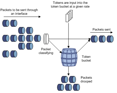
Figure 1-4 Evaluate the traffic with the token bucket
1) Evaluate the traffic with the token bucket
Traffic specification evaluation is based on whether the number of tokens in the bucket can meet the need of packet forwarding. If the number of tokens in the bucket is enough to forward the packets (generally, one token is associated with a 1-bit-forwarding authority), the traffic is conforming to the specification. Otherwise, the traffic is nonconforming or excess.
When the token bucket evaluates the traffic, its parameter configurations include:
l Average rate: The rate at which tokens are put into the bucket, namely, the permitted average rate of the traffic. It is generally set to committed information rate (CIR).
l Burst size: The capacity of the token bucket, namely, the maximum permitted size of every burst traffic. It is generally set to committed burst size (CBS). The set burst size must be bigger than the maximum packet length.
One evaluation is performed on each arriving packet. In each evaluation, if the number of tokens in the bucket is enough to forward the packet, the packet is conforming to the specification and you must take away some tokens whose number corresponds to the packet forwarding authority; if the number of tokens in the bucket is not enough to forward the packet, it means that too many tokens have been used and the traffic is excess.
2) Complicated evaluation
You can set two token buckets in order to evaluate traffic in more complicated conditions and implement more flexible traffic control policies. For example, the following 4 parameters are set for TP:
l CIR
l CBS
l Peak information rate (PIR)
l Excess burst size (EBS)
Two token buckets are used in this evaluation. The rates of putting tokens into the two buckets are CIR and PIR respectively, and the sizes of two buckets are CBS and EBS respectively (the two buckets are called C bucket and E bucket respectively for short), representing different permitted burst levels. In each evaluation, you can adopt different traffic control policies in different conditions, including “enough tokens in C bucket”, “insufficient tokens in C bucket but enough tokens in E bucket” and “insufficient tokens in both C bucket and E bucket”.
II. TP
A typical TP application is to supervise the specification of a traffic into the network and limit the specification within a reasonable range, or to punish the extra traffic. Therefore, the network resources and the interests of the operators are protected. For example, you can limit HTTP packets within 50% of the network bandwidth. If the traffic of a certain connection is excess, TP can choose to drop the packets or to reset the priority of the packets.
TP is widely used for policing the traffic into the network of internet service providers (ISP).TP can classify the policed traffic and perform pre-defined policing actions according to different evaluation results. These actions include:
l Forward: Forward the packet whose evaluation result is “conforming” or mark DSCP precedence for packets in the Diff-Serv network and then forward them.
l Drop: Drop the packet whose evaluation result is “nonconforming”.
l Remark the precedence and then forward: Remark the priority of the packet whose evaluation result is “partly-conforming” and then forward it.
1.1.9 Redirect
You can re-specify the forwarding port of a packet as required by your own QoS policy.
1.1.10 Queue Scheduling
When congestion occurs in the network, the problem that many packets compete for resources must be solved, usually in the way of queue scheduling.
1) SP queue
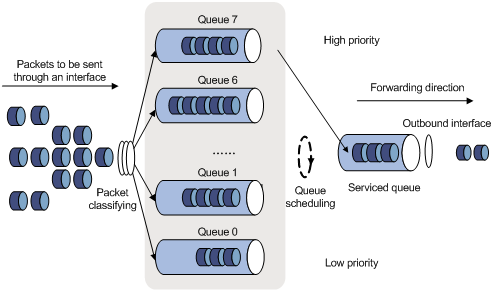
Figure 1-5 Diagram for SP queues
The SP queue-scheduling algorithm is specially designed for critical service applications. An important feature of critical services is that they demand preferential service in congestion in order to reduce the response delay. Assume that there are 8 output queues on a port and the SP queue scheduling algorithm classifies the 8 output queues on the port into 8 classes, which are queue7, queue6, queue5, queue4, queue3, queue2, queue1, and queue0. Their priorities decrease in order.
During the queue scheduling process, the SP algorithm sends packets in the queue with higher priority strictly following the priority order from high to low. When the queue with the highest priority is empty, packets in the queue with the second highest priority are sent. You can put critical service packets into the queues with higher priority and put non-critical service (such as e-mail) packets into the queues with lower priority. In this case, critical service packets are sent preferentially and non-critical service packets are sent when critical service packets are not sent.
2) WRR queue
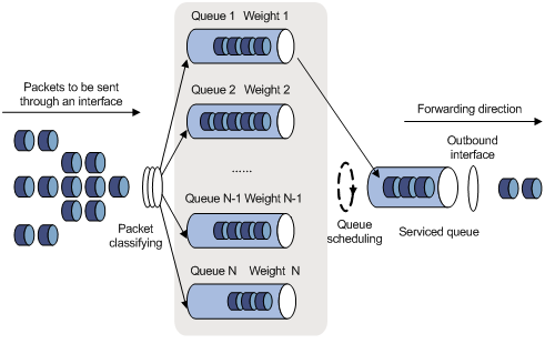
The WRR queue scheduling algorithm schedules all the queues in turn and every queue can be assured of a certain service time. Assume there are 8 priority queues on a port. The WRR queue scheduling algorithm assigns a weight value to each queue, which are w7, w6, w5, w4, w3, w2, w1, and w0 respectively. The weight value indicates the proportion of obtaining resources. On a 100M port, configure the weight value of WRR queue-scheduling algorithm to 50, 50, 30, 30, 10, 10, 10 and 10 to w7, w6, w5, w4, w3, w2, w1, and w0 respectively. In this way, the queue with the lowest priority can get 5Mbps bandwidth at least, and the disadvantage of the SP queue scheduling algorithm that the packets in queues with lower priority may get no service for a long time is avoided. Another advantage of the WRR queue scheduling algorithm is that: though the queues are scheduled in order, the service time for each queue is not fixed, that is to say, if a queue is empty, the next queue will be scheduled immediately. In this way, the bandwidth resources are fully utilized.
1.1.11 Traffic-based Traffic Statistics
1.1.12 RED
When severe congestion occurs, the switch can adopt the random early detection (RED) algorithm to solve the problem of excessive congestion and avoid global TCP synchronization caused by the tail-drop algorithm.
In the RED algorithm, an upper limit and a lower limit are set for each queue, and it is stipulated that:
l When the queue length is smaller than the lower limit, no packet is dropped.
l When the queue length is bigger than the upper limit, all received packets all dropped.
l When the queue length is in the range of the upper limit and the lower limit, the received packets are dropped at random. In this case, a number is assigned to each received packet and then compared with the drop probability of the current queue. If the assigned number is bigger than the drop probability, the received packet is dropped. The longer a queue is, the higher the drop probability is. However, there is a maximum drop probability.
In the RED algorithm, packets are dropped at random so that global TCP synchronization is avoided. When packets in a TCP connection are dropped and sent at a low rate, packets in other TCP connections are still sent at a high rate. In this way, packets in a part of TCP connections are sent at a high rate in any case. Thus, the utilization rate of bandwidth is improved.
1.2 QoS Supported by the S7500 Series Ethernet Switches
Table 1-4 QoS features supported by the S7500 series Ethernet switches and related commands
|
QoS |
Specification |
Related command |
|
Priority mapping |
Support only the 802.1p-priority-to-local-queue mapping |
qos cos-local-precedence-map |
|
Port priority |
Supported |
priority priority-level |
|
Priority according to which a packet is put into an output queue |
Supported |
priority-trust |
|
TP |
Supported |
traffic-limit |
|
Priority marking |
Supported |
traffic-priority |
|
Redirect |
Supported |
traffic-redirect |
|
Queue scheduling |
Support SP, RR and WRR |
queue-scheduler |
|
Rate limiting |
Supported |
line-rate |
|
Guaranteed bandwidth |
Supported |
traffic-bandwidth |
|
Congestion avoidance |
RED operation |
traffic-red |
|
Traffic statistics |
Supported |
traffic-statistic |
|
Inbound CAR |
Supported |
inboundcar { enable | disable } |
|
Traffic-based selective QinQ |
Supported |
traffic-remark-vlanid inbound acl-rule [ system-index ] remark-vlan vlan-id |
1.3 Setting Port Priority
If a received packet is not VLAN-tagged, the switch will tag the packet with the default VLAN tag of the port receiving the packet. In this case, the port priority of the port receiving the packet is assigned to the 802.1p priority of the VLAN tag of the packet. In this case, you can set the port priority.
If the received packet is VLAN-tagged, the switch does not perform the operation above.
I. Configuration prerequisites
l The port whose priority is to be configured is specified
l The priority value of the specified port is specified
II. Configuration procedure
Follow these steps to set port priority:
|
To do… |
Use the command… |
Remarks |
|
Enter system view |
system-view |
— |
|
Enter Ethernet port view |
interface interface-type interface-number |
— |
|
Set the port priority |
priority priority-level |
Optional By default, the port priority is 0. |
III. Configuration example
# Set the port priority of Ethernet 2/0/1 to 7.
<H3C> system-view
[H3C] interface Ethernet2/0/1
[H3C-Ethernet2/0/1] undo priority
[H3C-Ethernet2/0/1] priority 7
1.4 Configuring Priority According to Which a Packet is Put into an Output Queue
When congestion occurs in the network, queue scheduling is generally adopted to solve the problem that multiple packets compete for resources.
A switch port supports eight output queues. The priority of each queue is different, and packets in the queue with higher priority are sent preferentially. The switch puts a packet into the corresponding queue according to the DSCP precedence, IP precedence, 802.1p priority or local precedence of the packet. The mapping relationship between precedence values and queues are shown in Table 1-5, Table 1-6, Table 1-7, and Table 1-8.
Table 1-5 The 802.1p-priority-to-queue mapping
|
802.1p priority (CoS) |
Queue |
|
0 |
2 |
|
1 |
0 |
|
2 |
1 |
|
3 |
3 |
|
4 |
4 |
|
5 |
5 |
|
6 |
6 |
|
7 |
7 |
Table 1-6 The local-precedence–to-queue mapping
|
Local precedence |
Queue |
|
0 |
0 |
|
1 |
1 |
|
2 |
2 |
|
3 |
3 |
|
4 |
4 |
|
5 |
5 |
|
6 |
6 |
|
7 |
7 |
Table 1-7 The IP-precedence–to-queue mapping
|
IP precedence |
Queue |
|
0 |
0 |
|
1 |
1 |
|
2 |
2 |
|
3 |
3 |
|
4 |
4 |
|
5 |
5 |
|
6 |
6 |
|
7 |
7 |
Table 1-8 The DSCP-precedence–to-queue mapping
|
DSCP precedence value |
Name of type-A LPU |
Name of non-type-A LPU |
Queue |
|
0 to 7 |
be(0) |
be(0) |
0 |
|
8 to 15 |
cs1(8), af1(10) |
cs1(8), af11(10), af12(12), af13(14) |
1 |
|
16 to 23 |
cs2(16), af2(18) |
cs2(16), af21(18), af22(20), af23(22) |
2 |
|
24 to 31 |
cs3(24), af3(26) |
cs3(24), af31(26), af32(28), af33(30) |
3 |
|
32 to 39 |
cs4(32), af4(34) |
cs4(32), af41(34) , af42(36) , af43(38) |
4 |
|
40 to 47 |
cs5(40), ef(46) |
cs5(40), ef(46) |
5 |
|
47 to 55 |
cs6(48) |
cs6(48) |
6 |
|
56 to 63 |
cs7(56) |
cs7(56) |
7 |
& Note:
For LPUs that are not of A-type, if you specify the trusted priority for adding packets to output queues by using the priority-trust dscp or priority-trust ip-precedence command, the switch will convert the DSCP precedence or IP precedence of the received packets to the corresponding CoS precedence according to the DSCP-CoS precedence mapping table or IP-CoS precedence mapping table and then add the packets to the corresponding queues by CoS priority. In this case, the precedence is converted as follows.
l DSCP precedence 0 through 7 are mapped to CoS precedence 2; 8 through 15 to CoS precedence 0; 16 through 23 to CoS precedence 1; 24 through 31 to CoS precedence 3; 32 through 39 to CoS precedence 4; 40 through 47 to CoS precedence 5, 48 through 55 to CoS precedence 6; 56 through 63 to CoS precedence 7.
l IP precedence 0 is mapped to CoS precedence 2; IP precedence 1 to CoS precedence 0; IP precedence 2 to CoS precedence 1; IP precedence 3 to CoS precedence 3. The others are as those listed in Table 1-7.
1.4.1 Setting the Priority According to Which a Packet is Put into an Output Queue
You can select a type of priority as the basis for a packet to be put into an output queue on a port as required.
I. Configuration prerequisites
The priority according to which a packet is put into an output queue is specified.
II. Configuration procedure
Follow these steps to set the priority according to which a packet is put into an output queue:
|
To do… |
Use the command… |
Remarks |
|
Enter system view |
system-view |
— |
|
Configure the priority according to which a packet is put into an output queue |
priority-trust { dscp | ip-precedence | cos | local-precedence } |
Required By default, a queue is put into an output queue on a port according to the local precedence of the packet. |
III. Configuration example
# Configure to put a packet into an output queue according to the DSCP precedence of the packet.
<H3C> system-view
[H3C] priority-trust dscp
1.4.2 Configuring the 802.1p-Priority–to-Queue Mapping
You can modify the 802.1p-priority–to-local-precedence mapping to modify the 802.1p-priority-to–queue mapping.
I. Configuration prerequisites
The default 802.1p-priority–to-local-precedence mapping table is well known.
II. Configuration procedure
Follow these steps to configure the COS-to-local-precedence mapping table:
|
To do… |
Use the command… |
Remarks |
|
Enter system view |
system-view |
— |
|
Configure the COS-to-local-precedence mapping table |
qos cos-local-precedence-map cos0-map-local-prec cos1-map-local-prec cos2-map-local-prec cos3-map-local-prec cos4-map-local-prec cos5-map-local-prec cos6-map-local-prec cos7-map-local-prec |
Optional |
|
Display the mapping table |
display qos cos-local-precedence-map |
Optional You can execute the display command in any view. |
III. Configuration example
l Configure the 802.1p-to-local-precedence mapping as follows: 0 to 2, 1 to 3, 2 to 4, 3 to 1, 4 to 7, 5 to 0, 6 to 5 and 7 to 6.
l Display the configuration.
Configuration procedure:
<H3C> system-view
[H3C] qos cos-local-precedence-map 2 3 4 1 7 0 5 6
[H3C] display qos cos-local-precedence-map
cos-local-precedence-map:
cos : 0 1 2 3 4 5 6 7
--------------------------------------------------------------------------
local-precedence : 2 3 4 1 7 0 5 6
1.5 Configuring Priority Marking
Refer to Priority Marking for the introduction to priority marking.
Priority marking can be implemented in the following ways:
l Through TP (only non-type-A LPUs support this feature). When configuring TP, you can define the action of remarking the DSCP precedence for the packets exceeding the traffic limit. Refer to Configuration Procedure of TP.
l Through the traffic-priority command. Refer to the following description in this section.
1.5.1 Configuration Prerequisites
l ACL rules used for traffic identifying are defined. Refer to the ACL module in this manual for defining ACL rules.
l The type and value of the precedence that the packets matching ACL rules are remarked are specified
l The ports which need this configuration are specified
1.5.2 Configuration Procedure
Follow these steps to configure priority marking:
|
To do… |
Use the command… |
Remarks |
|
Enter system view |
system-view |
— |
|
Enter Ethernet port view |
interface interface-type interface-number |
— |
|
Enter QoS view |
qos |
— |
|
Use ACL rules for traffic identifying and assign a new precedence for the packets matching the ACL rules |
traffic-priority { inbound | outbound } acl-rule [ system-index ] { { dscp dscp-value | ip-precedence pre-value } | local-precedence pre-value }* |
Required Type-A LPUs support this command. |
|
traffic-priority inbound acl-rule [ system-index ] { { dscp dscp-value | ip-precedence pre-value } | { cos cos | local-precedence pre-value } }* |
Required Non-type-A LPUs support this command. |
|
|
Display the priority marking settings |
display qos-interface [ interface-type interface-number ] traffic-priority |
Optional You can execute the display command in any view. |
|
Display all the QoS settings of the port |
display qos-interface [ interface-type interface-number ] all |
acl-rule: Applied ACL rules which can be the combination of various ACL rules. The way of combination is described in the following table (Table 1-9 for type-A LPUs and Table 1-10 for non-type-A LPUs).
Table 1-9 Type-A LPUs’ ways of applying combined ACLs
|
ACL combination |
Form of the acl-rule argument |
|
Apply all the rules in an IP ACL separately |
ip-group { acl-number | acl-name } |
|
Apply a rule in an IP ACL separately |
ip-group { acl-number | acl-name } rule rule-id |
|
Apply all the rules in a Link ACL separately |
link-group { acl-number | acl-name } |
|
Apply a rule in a Link ACL separately |
link-group { acl-number | acl-name } rule rule-id |
Table 1-10 Non-type-A LPUs’ ways of applying combined ACLs
|
ACL combination |
Form of the acl-rule argument |
|
Apply all the rules in an IP ACL separately |
ip-group { acl-number | acl-name } |
|
Apply a rule in an IP ACL separately |
ip-group { acl-number | acl-name } rule rule-id |
|
Apply all the rules in a Link ACL separately |
link-group { acl-number | acl-name } |
|
Apply a rule in a link ACL separately |
link-group { acl-number | acl-name } rule rule-id |
|
Apply all the rules in a user-defined ACL separately |
user-group { acl-number | acl-name } |
|
Apply a rule in a user-defined ACL separately |
user-group { acl-number | acl-name } rule rule-id |
|
Apply a rule in an IP ACL and a rule in a link ACL at the same time |
ip-group { acl-number | acl-name } rule rule-id link-group { acl-number | acl-name } rule rule-id |
& Note:
Priority marking configuration is effective only for ACL rules defined with the permit keyword specified.
1.5.3 Configuration Example
l A switch is connected to 10.1.1.1/24 network segment through its Ethernet 2/0/1 port.
l Remark the DSCP precedence of the traffic from the 10.1.1.1/24 network segment to 56.
Configuration procedure:
<H3C> system-view
[H3C] acl number 2000
[H3C-acl-basic-2000] rule permit source 10.1.1.1 0.0.0.255
[H3C-acl-basic-2000] quit
[H3C] interface Ethernet2/0/1
[H3C-Ethernet2/0/1] qos
[H3C-qoss-Ethernet2/0/1] traffic-priority inbound ip-group 2000 dscp 56
1.6 Configuring Rate Limiting on a Port
1.6.1 Configuration Prerequisites
l The port where rate limiting is to be performed is determined.
l The target rate is specified.
1.6.2 Configuration Procedure
Follow these steps to configure rate limit on a port:
|
To do… |
Use the command… |
Remarks |
|
Enter system view |
system-view |
— |
|
Enter Ethernet port view |
interface interface-type interface-number |
— |
|
Enter QoS view |
qos |
— |
|
Configure port-based rate limiting |
line-rate [ kbps ] target-rate |
Required |
& Note:
Only non-type-A LPUs support port-based rate limiting.
1.6.3 Configuration Example
l Configure rate limiting on GigabitEthernet 2/0/1 of the switch
l Limit the rate to 10 Mbps.
Configuration procedure:
<H3C> system-view
[H3C] interface GigabitEthernet2/0/1
[H3C-GigabitEthernet2/0/1] qos
[H3C-qosb-GigabitEthernet2/0/1] line-rate 10
1.7 Configuring TP
Refer to TP for information about TP.
1.7.1 Configuration Prerequisites
l ACL rules used for traffic identifying are defined. Refer to the ACL module in this manual for defining ACL rules.
l The limit rate for TP, the actions for the packets within the specified traffic specification and the actions for the packets beyond the specified traffic specification have been specified.
l The ports that need this configuration are specified.
1.7.2 Configuration Procedure of TP
Follow these steps to configure TP:
|
To do… |
Use the command… |
Remarks |
|
Enter system view |
system-view |
— |
|
Enter Ethernet port view |
interface interface-type interface-number |
— |
|
Enter QoS view |
qos |
— |
|
Configure traffic-based TP |
traffic-limit { inbound | outbound } acl-rule [ system-index ] target-rate |
Required Type-A LPUs support this command. |
|
traffic-limit inbound acl-rule [ system-index ] [ kbps ] target-rate [ exceed action ] |
Required Non-type-A LPUs support this command. |
|
|
Display the parameters for TP |
display qos-interface [ interface-type interface-number ] traffic-limit |
Optional You can execute the display command in any view. |
|
Display all the QoS settings of the port |
display qos-interface [ interface-type interface-number ] all |
acl-rule: Applied ACL rules which can be the combination of various ACL rules. Type-A LPUs’ ways of combinations are described in Table 1-9, and non-type-A LPUs’ ways of combination are described in Table 1-10.
& Note:
l TP configuration is effective only for the permit rules in ACLs.
l When a switch is connected to a RADIUS server, if the switch does not support the inbound TP or outbound TP configured on the RADIUS server, the TP configuration will be ignored on the switch.
1.7.3 Configuration Example
l A switch is connected to 10.1.1.1/24 network segment through its GigabitEthernet 2/0/1 port.
l Perform TP on the packets from the 10.1.1.1/24 network segment and the rate of TP is set to 128 kbps.
l The packets beyond the specified traffic specification are forwarded after their DSCP precedence is marked as 56.
Configuration procedure:
<H3C> system-view
[H3C] acl number 2000
[H3C-acl-basic-2000] rule permit source 10.1.1.1 0.0.0.255
[H3C-acl-basic-2000] quit
[H3C] interface GigabitEthernet2/0/1
[H3C-GigabitEthernet2/0/1] qos
[H3C-qosb-GigabitEthernet2/0/1] traffic-limit inbound ip-group 2000 kbps 128 exceed remark-dscp 56
1.8 Configuring Redirect
Refer to Redirect for the introduction to redirect.
1.8.1 Configuration Prerequisites
l ACL rules used for traffic identifying are defined. Refer to the ACL module in this manual for defining ACL rules.
l The port that the packets are to be redirected to is specified.
l The ports that need this configuration are specified.
1.8.2 Configuration Procedure
Follow these steps to configure redirect:
|
To do… |
Use the command… |
Remarks |
|
Enter system view |
system-view |
— |
|
Enter Ethernet port view |
interface interface-type interface-number |
— |
|
Enter QoS view |
qos |
— |
|
Configure redirect |
traffic-redirect inbound acl-rule [ system-index ] { cpu | interface interface-type interface-number } |
Required |
|
Display the parameters for traffic redirect |
display qos-interface [ interface-type interface-number ] traffic-redirect |
Optional You can execute the display command in any view. |
|
Display all the QoS settings of the port |
display qos-interface [ interface-type interface-number ] all |
acl-rule: Applied ACL rules which can be the combination of various ACL rules. The way of combination is described in Table 1-10.
& Note:
l Only non-type-A LPUs support the traffic redirect configuration.
l In a traffic redirect configuration, the source port and the destination port must be on the same LPU.
l The redirect configuration is effective only for ACL rules defined with the permit keyword specified.
l When packets are redirected to the CPU, they cannot be forwarded normally.
1.8.3 Configuration Example
l A switch is connected to 10.1.1.1/24 network segment through its Ethernet 2/0/1 port.
l Redirect all the traffic from the 10.1.1.1/24 network segment to GigabitEthernet 2/0/7.
Configuration procedure:
<H3C> system-view
[H3C] acl number 2000
[H3C-acl-basic-2000] rule permit source 10.1.1.1 0.0.0.255
[H3C-acl-basic-2000] quit
[H3C] interface GigabitEthernet2/0/1
[H3C-GigabitEthernet2/0/1] qos
[H3C-qosb-GigabitEthernet2/0/1] traffic-redirect inbound ip-group 2000 interface GigabitEthernet 2/0/7
1.9 Configuring Queue Scheduling
Refer to Queue Scheduling for the introduction to queue scheduling.
1.9.1 Configuration Prerequisites
l The queue-scheduling algorithm is specified.
l The ports that need this configuration are specified.
1.9.2 Configuration Procedure
Follow these steps to configure queue scheduling:
|
To do… |
Use the command… |
Remarks |
|
Enter system view |
system-view |
— |
|
Enter Ethernet port view |
interface interface-type interface-number |
— |
|
Enter QoS view |
qos |
— |
|
Configure the queue scheduling mode |
queue-scheduler { rr | strict-priority | wrr queue1-weight queue2-weight queue3-weight queue4-weight queue5-weight queue6-weight queue7-weight queue8-weight } |
Required By default, the SP queue scheduling algorithm is adopted. |
|
Display the parameters for traffic redirect |
display qos-interface [ interface-type interface-number ] queue-scheduler |
Optional You can execute the display command in any view. |
|
Display all the QoS settings on the port |
display qos-interface [ interface-type interface-number ] all |
& Note:
Only non-type-A LPUs support the configuration for the queue scheduling algorithm.
1.9.3 Configuration Example
l The switch adopts the WRR queue scheduling algorithm, and the weight values of output queues are 10, 5, 10, 10, 5, 10, 5, and 10 respectively;
l Display the configuration.
Configuration procedure:
<H3C> system-view
[H3C] interface GigabitEthernet2/0/1
[H3C-GigabitEthernet2/0/1] qos
[H3C-qosb-GigabitEthernet2/0/1] queue-scheduler wrr 10 5 10 10 5 10 5 10
[H3C-qosb-GigabitEthernet2/0/1] display qos-interface GigabitEthernet 1/0/1 queue-scheduler
GigabitEthernet2/0/1:
Queue scheduling mode: weighted round robin
weight of queue 1: 10
weight of queue 2: 5
weight of queue 3: 10
weight of queue 4: 10
weight of queue 5: 5
weight of queue 6: 10
weight of queue 7: 5
weight of queue 8: 10
COS configuration:
Config (max queues): 8
Schedule mode: weighted round-robin
Weighting (in packets):
COSQ 0 = 10 packets
COSQ 1 = 5 packets
COSQ 2 = 10 packets
COSQ 3 = 10 packets
COSQ 4 = 5 packets
COSQ 5 = 10 packets
COSQ 6 = 5 packets
COSQ 7 = 10 packets
Egress port queue statistics(in bytes):
Priority CosQ Threshold Count Used(%):
0 2 18432 0 0
1 0 2560 0 0
2 1 2560 0 0
3 3 2560 0 0
4 4 2560 0 0
5 5 2560 0 0
6 6 2560 0 0
7 7 2560 0 0
common queue statistics(in bytes):
49152 0 0
1.10 Configuring Congestion Avoidance
When congestion occurs, the switch will drop packets as soon as possible to release queue resources and try not to put packets into high-delay queues in order to eliminate congestion. The switch adopts the RED algorithm for congestion avoidance.
1.10.1 Configuration Prerequisites
l The indexes of queues to be dropped at random, the queue length that starts the drop action, the queue length that causes all the packets to be dropped and the drop probability are specified.
l The ports that need this configuration are specified.
1.10.2 Configuration Procedure
Follow these steps to configure RED parameters:
|
To do… |
Use the command… |
Remarks |
|
Enter system view |
system-view |
— |
|
Enter Ethernet port view |
interface interface-type interface-number |
— |
|
Enter QoS view |
qos |
— |
|
Configure parameters for the RED algorithm |
traffic-red outbound acl-rule [ system-index ] qstart qstop probability |
Required The maximum available bandwidth must be no smaller than the minimum guaranteed bandwidth. |
|
Display the parameters for the RED algorithm |
display qos-interface [ interface-type interface-number ] traffic-red |
Optional You can execute the display command in any view. |
|
Display all the QoS settings on the port |
display qos-interface [ interface-type interface-number ] all |
acl-rule: Applied ACL rules which can be the combination of various ACL rules. The way of combination is described in Table 1-10.
& Note:
l Only type-A LPUs support the configurations above.
l Only the permit rules in ACLs can be properly applied to the hardware.
1.10.3 Configuration Example
l A switch is connected to 10.1.1.1/24 network segment through its Ethernet 2/0/1 port.
l Perform RED queue scheduling for all the traffic from the network segment 10.1.1.1/24.
l Set the parameters as follows: the packets are dropped at random when the queue length exceeds 64 Kbytes, all packets are dropped when the queue length exceeds 128 Kbytes, and the drop probability is 20%.
Configuration procedure:
<H3C> system-view
[H3C] acl number 2000
[H3C-acl-basic-2000] rule permit source 10.1.1.1 0.0.0.255
[H3C-acl-basic-2000] quit
[H3C] interface Ethernet2/0/1
[H3C-Ethernet2/0/1] qos
[H3C-qoss-Ethernet2/0/1] traffic-red outbound ip-group 2000 64 128 20
1.11 Configuring Traffic Statistics
Refer to Traffic-based Traffic Statistics for the introduction to traffic statistics.
1.11.1 Configuration Prerequisites
l ACL rules used for traffic identifying are defined. Refer to the ACL module in the book for defining ACL rules.
l The ports that need this configuration are specified.
1.11.2 Configuration Procedure of Traffic Statistics
Follow these steps to configure traffic statistics:
|
To do… |
Use the command… |
Remarks |
|
Enter system view |
system-view |
— |
|
Enter Ethernet port view |
interface interface-type interface-number |
— |
|
Enter QoS view |
qos |
— |
|
Use the ACL rules in traffic identifying and perform traffic statistics on the packets matching the ACL rules |
traffic-statistic { inbound | outbound } acl-rule [ system-index ] |
Required Type A LPUs support this command. |
|
traffic-statistic inbound acl-rule [ system-index ] |
Required Non-type-A LPUs support this command. |
|
|
Display the traffic statistics |
display qos-interface [ interface-type interface-number ] |
Optional You can execute the display command in any view. |
|
Display all the QoS settings of the port |
display qos-interface [ interface-type interface-number ] all |
acl-rule: Applied ACL rules which can be the combination of various ACL rules. Type-A LPUs’ way of combination is described in Table 1-9, and non-type-A LPUs’ way of combination is described in Table 1-10.
1.11.3 Clearing Traffic Statistics Information
Follow these steps to clear traffic statistics information:
|
To do… |
Use the command… |
Remarks |
|
Enter system view |
system-view |
— |
|
Enter Ethernet port view |
interface interface-type interface-number |
— |
|
Enter QoS view |
qos |
— |
|
Clear the statistics of the traffic matching the specified ACL rules |
reset traffic-statistic { inbound | outbound } acl-rule [ system-index ] |
Required Type-A LPUs support this command. |
|
reset traffic-statistic inbound acl-rule [ system-index ] |
Required Non-type-A LPUs support this command. |
acl-rule: Applied ACL rules which can be the combination of various ACL rules. Type-A LPUs’ way of combination is described in Table 1-9, and non-type-A LPUs’ way of combination is described in Table 1-10.
1.11.4 Configuration Example
l A switch is connected to 10.1.1.1/24 network segment through its Ethernet 2/0/1 port.
l Collect statistics on traffic from the 10.1.1.1/24 network segment
Configuration procedure:
<H3C> system-view
[H3C] acl number 2000
[H3C-acl-basic-2000] rule permit source 10.1.1.1 0.0.0.255
[H3C-acl-basic-2000] quit
[H3C] interface Ethernet2/0/1
[H3C-Ethernet2/0/1] qos
[H3C-qoss-Ethernet2/0/1] traffic-statistic inbound ip-group 2000
1.12 Configuring Guaranteed Bandwidth
The guaranteed bandwidth feature is to provide the maximum available bandwidth and minimum guaranteed bandwidth for the specified traffic to get the corresponding service.
1.12.1 Configuration Prerequisites
l ACL rules used for traffic identifying are defined. Refer to the ACL module in this manual for defining ACL rules.
l The parameters for the guaranteed bandwidth are specified.
l The ports that need this configuration are specified.
1.12.2 Configuration Procedure
Follow these steps to configure guaranteed bandwidth:
|
To do… |
Use the command… |
Remarks |
|
Enter system view |
system-view |
— |
|
Enter Ethernet port view |
interface interface-type interface-number |
— |
|
Enter QoS view |
qos |
— |
|
Enable ACLs to identify traffic and provide guaranteed bandwidth for the specified traffic |
traffic-bandwidth outbound acl-rule [ system-index ] min-guaranteed-bandwidth max-guaranteed-bandwidth weight |
Required The maximum available bandwidth must be no smaller than the minimum guaranteed bandwidth. |
|
Display the traffic statistics information |
display qos-interface [ interface-type interface-number ] traffic-bandwidth |
Optional You can execute the display command in any view. |
|
Display all the QoS settings on the port |
display qos-interface [ interface-type interface-number ] all |
acl-rule: Applied ACL rules which can be the combination of various ACL rules. Type-A LPUs’ way of combination is described in Table 1-9, and non-type-A LPUs’ way of combination is described in Table 1-10.
& Note:
l Only type-A LPUs support the configuration above.
l Only the permit rules in ACLs can be properly applied to the hardware.
1.12.3 Configuration Example
l A switch is connected to 10.1.1.1/24 network segment through its Ethernet 2/0/1 port.
l Enable the guaranteed bandwidth feature for traffic from the network segment 10.1.1.1/24.
l Set the parameters as follows: the minimum guaranteed bandwidth is 64 kbps, the maximum available bandwidth is 128 kbps, and the weight of bandwidth is 50.
Configuration procedure:
<H3C> system-view
[H3C] acl number 2000
[H3C-acl-basic-2000] rule permit source 10.1.1.1 0.0.0.255
[H3C-acl-basic-2000] quit
[H3C] interface Ethernet2/0/1
[H3C-Ethernet2/0/1] qos
[H3C-qoss-Ethernet2/0/1] traffic-bandwidth outbound ip-group 2000 64 128 50
1.13 Configuring Inbound CAR
You can enable/disable the inbound committed access rate (CAR) feature.
With the inbound CAR feature enabled, when one ACL rule is applied to multiple ports, the switch regards the ACL rule applied to each port as different, so one ACL rule occupies multiple entries after it is applied. If you enable the inbound CAR feature for traffic matching the same ACL rule on multiple ports, each port can provide the guaranteed bandwidth for the inbound traffic matching the CAR rule.
With the inbound CAR feature disabled, when one ACL rule is applied to multiple ports, the switch regards the ACL rule applied to each port as the same, so one ACL rule occupies only one entry after it is applied. If you enable the CAR feature for traffic matching the same ACL rule on multiple ports, the switch will provide the guaranteed bandwidth for all the inbound traffic matching the CAR rule on multiple ports.
For example, if you want to allocate 2 M of CAR bandwidth to the inbound traffic matching ACL rule 0, you can use the traffic-limit command to enable the CAR feature on two ports.
l If the inbound CAR feature is enabled, each port guarantees 2 M of bandwidth for its own inbound traffic matching ACL rule 0.
l If the inbound CAR feature is disabled, the switch allocates 2 M of bandwidth for all the inbound traffic matching ACL rule 0 on the two ports.
1.13.1 Configuration Procedure
Follow these steps to configure the inbound CAR feature:
|
To do… |
Use the command… |
Remarks |
|
Enter system view |
system-view |
— |
|
Enable/Disable the inbound CAR feature |
inboundcar { enable | disable } |
Required By default, the inbound CAR feature is disabled. |
& Note:
The inboundcar command is applicable to A-type LPUs only and can only take effect after the switch is restarted.
1.13.2 Configuration Procedure
# Enable the inbound CAR feature.
<H3C> system-view
[H3C] inboundcar enable
1.14 Configuring Traffic-Based Selective QinQ
QinQ is to encapsulate the VLAN tags of the private network in the VLAN tags of the public network in order that the frames are transmitted through the backbone network of the service provider network (also called public network). The traffic-based selective QinQ feature can tag a frame with an outer VLAN tag according to the ACL rule that the frame matches on the inbound port.
The traffic-based selective QinQ feature is usually configured on the hybrid port of the edge device connecting the user device to the service provider network.
1.14.1 Configuration Prerequisites
l ACL rules used for traffic identifying are defined. Refer to the ACL module in this manual for defining ACL rules.
l ID of the outer VLAN tag is specified.
l The ports that needs this configuration are specified
1.14.2 Configuration Procedure
Follow these steps to configure the traffic-based selective QinQ feature:
|
To do… |
Use the command… |
Remarks |
|
Enter system view |
system-view |
— |
|
Create a VLAN |
vlan vlan-id |
The vlan-id argument is the ID of the outer VLAN tag. |
|
Enter Ethernet port view |
interface interface-type interface-number |
— |
|
Configure the port as a hybrid port |
port link-type hybrid |
— |
|
Add the port to the specified VLAN |
port hybrid vlan vlan-id { tagged | untagged } |
The vlan-id argument is the ID of the outer VLAN tag. |
|
Enable the QinQ feature in the port view |
vlan-vpn enable |
Required |
|
Enter QoS view |
qos |
— |
|
Enable the ACL rule for traffic identifying and tag the matching frames with outer VLAN tags |
traffic-remark-vlanid inbound acl-rule [ system-index ] remark-vlan vlan-id |
Required |
|
Display the traffic statistics |
display qos-interface [ interface-type interface-number ] traffic-remark-vlanid |
Required You can execute the display command in any view. |
|
Display all the QoS settings on the port |
display qos-interface [ interface-type interface-number ] all |
acl-rule: Applied ACL rules which can be the combination of various ACL rules. The way of combination is described in Table 1-11.
Table 1-11 The way of applying combined ACL rules
|
ACL combination |
Form of the acl-rule argument |
|
Apply all the rules in an IP ACL separately |
ip-group { acl-number | acl-name } |
|
Apply a rule in an IP ACL separately |
ip-group { acl-number | acl-name } rule rule-id |
|
Apply all the rules in a link ACL separately |
link-group { acl-number | acl-name } |
|
Apply a rule in a link ACL separately |
link-group { acl-number | acl-name } rule rule-id |
|
Apply a rule in an IP ACL and a rule in a link ACL at the same time |
ip-group { acl-number | acl-name } rule rule-id link-group { acl-number | acl-name } rule rule-id |
![]() Caution:
Caution:
l A-type LPUs, LS82GT20, and LS82GP20 do not support traffic-based selective QinQ.
l Execute the vlan-vpn enable command in the corresponding port view before executing the traffic-remark-vlanid command.
l The QinQ feature cannot be enabled on a port with Voice VLAN function enabled.
1.14.3 Configuration Example
l A switch is connected to 10.1.1.1/24 network segment through its Ethernet 2/0/1 port.
l Tag all the frames from the 10.1.1.1/24 network segment with outer VLAN tags to implement the traffic-based selective QinQ feature.
Configuration procedure:
<H3C> system-view
[H3C] vlan 25
[H3C-vlan25] quit
[H3C] acl number 2000
[H3C-acl-basic-2000] rule permit source 10.1.1.1 0.0.0.255
[H3C-acl-basic-2000] quit
[H3C] interface Ethernet2/0/1
[H3C-Ethernet2/0/1] port link-type hybrid
[H3C-Ethernet2/0/1] port hybrid vlan 25 untagged
[H3C-Ethernet2/0/1] vlan-vpn enable
[H3C-Ethernet2/0/1] qos
[H3C-qosb-Ethernet2/0/1] traffic-remark-vlanid inbound ip-group 2000 remark-vlan 25
1.15 QoS Configuration Examples
1.15.1 Configuration Example of TP and Rate Limiting on the Port
I. Network requirement
The enterprise network connects all the departments through the ports of the Ethernet switch. The salary query server of the financial department is accessed through Ethernet 2/0/1 with IP address 129.110.1.2. The network requirements are to limit the average rate of outbound traffic within 640kbps and set the precedence of packets exceeding the specification to 4.
II. Network diagram
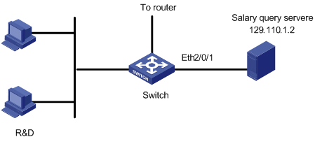
Figure 1-7 Network diagram for TP and rate limiting configuration
III. Configuration procedure
& Note:
Only the commands related to QoS/ACL configurations are listed in the following configurations.
1) Define the outbound traffic of the salary query server
# Enter ACL 3000 view.
<H3C> system-view
[H3C] acl number 3000
# Define ACL 3000 rules.
[H3C-acl-adv-3000] rule 1 permit ip source 129.110.1.2 0 destination any
[H3C-acl-adv-3000] quit
2) Limit the outbound traffic of the salary query server
# Limit the average rate of outbound traffic within 640kbps and set the precedence of packets exceeding the specification to 4.
[H3C] interface Ethernet2/0/1
[H3C-Ethernet2/0/1] qos
[H3C-qoss-Ethernet2/0/1] traffic-limit inbound ip-group 3000 640 exceed remark-dscp 4
1.15.2 Configuration Example of Priority Marking
I. Network requirements
Mark ef on the packets that PC1 with IP address 1.0.0.2 sends from 8:00 to 18:00 every day to provide the precedence for the upper-layer devices to use.
II. Network diagram
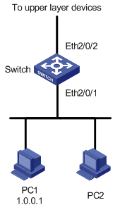
Figure 1-8 Network diagram for priority marking
III. Configuration procedure
1) Define the time rang from 8:00 to 18:00
# Define the time range.
<H3C> system-view
[H3C] time-range test 8:00 to 18:00 daily
2) Define the traffic rules of PC packets
# Enter number-identification-based basic ACL view identified.
[H3C] acl number 2000
[H3C-acl-basic-2000] rule 0 permit source 1.0.0.1 0 time-range test
[H3C-acl-basic-2000] quit
3) Mark the ef precedence on the packets PC1 sends
[H3C] interface Ethernet2/0/1
[H3C-Ethernet2/0/1] qos
[H3C-qoss-Ethernet2/0/1] traffic-priority inbound ip-group 2000 dscp ef