- Table of Contents
-
- H3C S7500 Series Operation Manual(Release 3100 Series)-(V1.04)
- 00-1Cover
- 00-2Overview
- 01-CLI Configuration
- 02-Login Configuration
- 03-Configuration File Management Configuration
- 04-VLAN Configuration
- 05-Extended VLAN Application Configuration
- 06-IP Address-IP Performance-IPX Configuration
- 07-GVRP Configuration
- 08-QinQ Configuration
- 09-Port Basic Configuration
- 10-Link Aggregation Configuration
- 11-Port Isolation Configuration
- 12-Port Binding Configuration
- 13-DLDP Configuration
- 14-MAC Address Table Configuration
- 15-MSTP Configuration
- 16-Routing Protocol Configuration
- 17-Multicast Configuration
- 18-802.1x Configuration
- 19-AAA-RADIUS-HWTACACS-EAD Configuration
- 20-Traffic Accounting Configuration
- 21-VRRP-HA Configuration
- 22-ARP Configuration
- 23-DHCP Configuration
- 24-ACL Configuration
- 25-QoS Configuration
- 26-Mirroring Configuration
- 27-Cluster Configuration
- 28-PoE Configuration
- 29-UDP-Helper Configuration
- 30-SNMP-RMON Configuration
- 31-NTP Configuration
- 32-SSH Terminal Service Configuration
- 33-File System Management Configuration
- 34-FTP and TFTP Configuration
- 35-Information Center Configuration
- 36-DNS Configuration
- 37-System Maintenance and Debugging Configuration
- 38-HWPing Configuration
- 39-RRPP Configuration
- 40-NAT-Netstream-Policy Routing Configuration
- 41-Telnet Protection Configuration
- 42-Hardware-Dependent Software Configuration
- Related Documents
-
| Title | Size | Download |
|---|---|---|
| 18-802.1x Configuration | 423 KB |
Table of Contents
Chapter 1 802.1x Configuration
1.1.1 Architecture of 802.1x Authentication
1.1.2 802.1x Authentication Mechanism
1.1.4 802.1x Authentication Procedure
1.1.6 802.1x Implementation on an S7500 Series Switch
1.3 Basic 802.1x Configuration
1.3.2 Configuring Basic 802.1x Functions
1.4 Timer and Maximum User Number Configuration
1.5 Advanced 802.1x Configuration
1.5.2 Configuring Proxy Detection
1.5.3 Configuring Client Version Checking
1.5.4 Enabling DHCP-triggered Authentication
1.6 Displaying and Debugging 802.1x
1.7.1 802.1x Configuration Example
Chapter 1 802.1x Configuration
When configuring 802.1x, go to these sections for information you are interested in:
l Timer and Maximum User Number Configuration
l Advanced 802.1x Configuration
l Displaying and Debugging 802.1x
1.1 Introduction to 802.1x
The 802.1x protocol (802.1x for short) was developed by IEEE802 LAN/WAN committee to address security issues of wireless LANs. It was then used in Ethernet as a common access control mechanism for LAN ports to address authentication and security problems.
802.1x is a port-based network access control protocol. It authenticates and controls devices attempting to access the LAN on the ports of access control devices. A device attached to a port can access the LAN only when it passes the authentication. Those failing to pass the authentication are denied, as if they were disconnected from the LAN.
This section covers these topics:
l Architecture of 802.1x Authentication
l 802.1x Authentication Mechanism
l 802.1x Authentication Procedure
l 802.1x Implementation on an S7500 Series Switch
1.1.1 Architecture of 802.1x Authentication
802.1x adopts a client/server architecture with three entities: a supplicant system, an authenticator system, and an authentication server system, as shown in Figure 1-1.
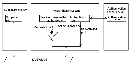
Figure 1-1 Architecture of 802.1x authentication
l The supplicant system is an entity residing at one end of the LAN segment and is authenticated by the authenticator system connected to the other end of the LAN segment. The supplicant system is usually a user terminal device. An 802.1x authentication is initiated when a user launches the 802.1x client program on the supplicant system. Note that the 802.1x client program must support the EAPoL (extensible authentication protocol over LANs).
l The authenticator system authenticates the supplicant system. The authenticator system is usually an 802.1x-supported network device (such as an H3C series switch). It provides a port (physical or logical) for the supplicant system to access the LAN.
l The authentication server system is an entity that provides authentication service to the authenticator system. Normally in the form of a RADIUS server, the authentication server system serves to perform AAA (authentication, authorization, and accounting) . It also stores user information, such as user name, password, the VLAN a user belongs to, priority, and the ACLs applied.
Following are the four basic concepts related with the above three entities, namely the PAE, controlled port and uncontrolled port, control direction and control mode.
I. PAE
A PAE (port access entity) is responsible for the implementation of algorithms and protocol operations in the authentication mechanism.
The authenticator system PAE authenticates supplicant systems through the authentication server when they log into the LAN and controls the authorizing state of the controlled ports according to the authentication results.
The supplicant system PAE responds to the authentication requests received from the authenticator system and submits user authentication information to the authenticator system. It can also send authentication and disconnection requests to the authenticator system PAE.
II. Controlled port and uncontrolled port
The authenticator system provides ports for supplicant systems to access a LAN. A port of this kind is divided into two virtual ports: a controlled port and an uncontrolled port.
l The uncontrolled port can always send and receive packets. It mainly serves to forward EAPoL packets to ensure that a supplicant system can make authentication requests or be authenticated.
l The controlled port can be used to pass service packets when it is in authorized state. However, It is disconnected when the controlled port is not in authorized state. In this case, no packets can pass through the controlled port.
l Controlled port and uncontrolled port are two parts of a port. Packets arriving the port are visible to both the controlled port and the uncontrolled port.
III. Control direction
In unauthorized state, the controlled port can be set to a unidirectionally controlled port, which is allowed to send packets to supplicant systems only.
By default, a controlled port is a unidirectionally controlled port.
IV. Control mode
For port control, two ways are supported:
l Port-based authentication. In this mode, all the supplicant systems connected to the physical port can access the network without being authenticated after one of them passes authentication. Similarly, when one of authenticated supplicant systems goes offline, the others are denied.
l MAC address-based authentication. All supplicant systems connected to the physical port have to be authenticated individually in order to access the network. And when a supplicant system goes offline, the others are not affected.
1.1.2 802.1x Authentication Mechanism
IEEE 802.1x authentication system uses extensible authentication protocol (EAP) as a means of exchanging authentication information between the supplicant system and the authentication server.
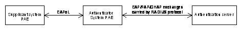
Figure 1-2 802.1x authentication mechanism
l Between the supplicant system and the authenticator system, EAP protocol packets are encapsulated in EAPoL packets and transmitted over the LAN.
l Between the authenticator system PAE and the RADIUS server, EAP protocol packets can either be encapsulated in EAPoR (EAP over RADIUS) packets or be terminated at the authenticator system PAE. The authenticator system PAE then communicates with the RADIUS server through PAP (password authentication protocol) or CHAP (challenge-handshake authentication protocol) packets.
l When a supplicant system passes authentication, the authentication server passes the information about the supplicant system to the authenticator system. Then the authenticator system determines the state (authorized or unauthorized) of the controlled port according to the instruction (accept or reject) received from the RADIUS server.
1.1.3 EAPoL Encapsulation
I. EAPoL packet format
EAPoL is a packet encapsulation format defined in 802.1x. It is designed to transmit EAP protocol packets between suppliant systems and authenticator systems over LANs. The following figure illustrates the format of an EAPoL packet.
![]()
Figure 1-3 The format of an EAPoL packet
In an EAPoL packet:
l The PAE Ethernet type field holds protocol type, with 0x888E being 802.1x.
l The Protocol version field holds the version of the protocol supported by the sender of EAPoL packets.
l The Type field can be one of the following:
EAP-Packet (00): a packet used to carry authentication information;
EAPoL-Start (01): a packet used to initiate authentication;
EAPoL-Logoff (02): a packet used to send logging off request;
EAPoL-Key (03): a packet used to carry key information;
EAPoL-Encapsulated-ASF-Alert (04): a packet used to support the alerting messages of alerting standards forum (ASF).
l The Length field indicates the size of the Packet body field. A value of 0 indicates that the Packet body field does not exist.
l The Packet body field varies with the Type field.
Note that EAPoL-Start, EAPoL-Logoff, and EAPoL-Key packets are only transmitted between the supplicant system and the authenticator system. EAP-packets are encapsulated by the RADIUS protocol to traverse through complicated networks and successfully reach the authentication server. Network management-related information (such as alarming information) is encapsulated in EAPoL-Encapsulated-ASF-Alert packets, which are terminated by the authenticator system.
II. EAP packet format
For an EAPoL packet with the Type value being EAP-packet, the corresponding Packet body is an EAP packet. Its format is illustrated in Figure 1-4.
![]()
Figure 1-4 The format of an EAP packet
In an EAP packet:
l The Code field specifies the EAP packet type, which can be Request, Response, Success, or Failure.
l The Identifier field helps match Response and Request messages.
l The Length field indicates the size of an EAP packet, which includes the Code, Identifier, Length, and Data fields.
l The Data field varies with the Code field.
A Success or Failure type EAP packet does not contain the Data field. Accordingly the Length field is 4.
Figure 1-5 shows the format of Data field of Request and Response type packets.
![]()
Figure 1-5 The format of Data field of Request and Response type packets
l The Type field specifies the EAP authentication type. A value of 1 represents Identity, indicating that the packet is for querying the identity of the supplicant. A value of 4 represents MD5 Challenge (similar to PPP CHAP protocol), including query information.
l The Type Date field varies with different types of Request and Response packets.
III. EAP attribute encapsulation
Two attributes, EAP-message and Message-authenticator, are added for EAP authentication. (For information about RADIUS packet format, refer to the Introduction to RADIUS protocol section in AAA-RADIUS-HWTACACS-EAD Operation Manual.)
As shown in Figure 1-6, the EAP-message attribute is used to encapsulate EAP packets. The type code is 79. The maximum size of the string field is 253 bytes. EAP packets with their sizes larger than 253 bytes are fragmented and stored in multiple EAP-message fields orderly.
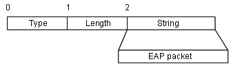
Figure 1-6 Encapsulation format of the EAP-message attribute
The Message-authenticator attribute, as shown in Figure 1-7, is used to prevent access requesting packets from being snooped during authentications using CHAP, EAP, and so on. A packet with the EAP-message attribute must also have the Message-authenticator attribute; otherwise the packet is regarded as invalid and will be discarded.
![]()
Figure 1-7 Encapsulation format of the Message-authenticator attribute
1.1.4 802.1x Authentication Procedure
An H3C S7500 series switch can authenticate supplicant systems in EAP termination mode or EAP relay mode.
I. EAP relay mode
This mode is defined in 802.1x. In this mode, EAP protocol is carried over other upper layer protocols like EAP over RADIUS so that EAP packets can traverse through complicated networks and arrive the authentication server. This mode normally requires the RADIUS server to support the two newly added attributes: EAP-message (a value of 79) and Message-authenticator (a value of 80).
For EAP relay mode, three authentication ways are supported: EAP-MD5, transport layer security (EAP-TLS ), and protected extensible authentication protocol (PEAP). The following presents a description of these three authentication ways:
l EAP-MD5 authenticates the supplicant system. The RADIUS server sends MD5 keys (contained in EAP-request/MD5 challenge packets) to the supplicant system, which in turn encrypts passwords using the MD5 keys.
l EAP-TLS authenticates both the supplicant system and the RADIUS server. With MAP-TLS authentication, the supplicant system and the RADIUS server checks the security certificate of each other to prevent data from being stolen.
l PEAP creates and uses TLS security channels to ensure data integrity and then performs new EAP negotiation to verify the supplicant system.
Figure 1-8 takes EAP-MD5 as an example to introduce basic authentication procedure.
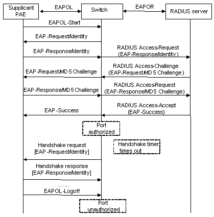
Figure 1-8 802.1x authentication procedure (in EAP relay mode)
The detailed procedure is as follows.
l To access the Internet, a supplicant system launches an 802.1x client, inputs the applied and registered username and password, and initiates a connection request (an EAPoL-Start packet). The 802.1x client program then forwards the packet to the switch to start an authentication process.
l Upon receiving the authentication request packet, the switch sends a request frame (an EAP-Request/Identity packet) to ask the 802.1x client for the inputted user name.
l The 802.1x client responds by sending the user name in a frame (an EAP-Response/Identity packet) to the switch. The switch then encapsulates the frame in an RADIUS Access-Request packet and forwards it to the RADIUS server for processing.
l Upon receiving the user name from the switch, the RADIUS server maps it to its database to retrieve the corresponding password. Then it uses a randomly generated key to encrypt the password while sending the key to the switch in an RADIUS Access-Challenge packet. The switch then sends the key to the 802.1x client.
l Upon receiving the key (an EAP-Request/MD5 Challenge packet) from the switch, the 802.1x client program encrypts the password of the supplicant system with the key and sends the encrypted password (encapsulated in an EAP-response/MD5 challenge packet) to the RADIUS server through the switch. (The encryption is irreversible.)
l The RADIUS server compares the received encrypted password (contained in an RADIUS Access-Request packet) with the locally encrypted password. If the two passwords match, it will send feedbacks (through RADIUS Access-Accept packet and EAP-Success packet) to the switch, indicating that the supplicant system is authorized.
l The switch changes the state of the corresponding port to authorized state, allowing the supplicant system to access the network.
l The supplicant system can also terminate the authenticated state by sending an EAPoL-Logoff packet to the switch. The switch then changes the port state from authorized to unauthorized.
& Note:
In EAP relay mode, packets are not modified during transmission. Therefore if one of the three ways are used (that is, PEAP, EAP-TLS, or EAP-MD5) to authenticate, ensure that the authentication ways used on the supplicant system and the RADIUS server are the same. On the switch, however, you can simply enable the EAP relay mode by using the dot1x authentication-method eap command.
II. EAP termination mode
In this mode, packet transmission is terminated at the authenticator system and EAP packets are converted to RADIUS packets. Authentication and accounting are accomplished through the RADIUS protocol.
In this mode, PAP or CHAP authentication is employed between the switch and the RADIUS server. The following figure takes CHAP authentication as an example to illustrate basic authentication procedure.
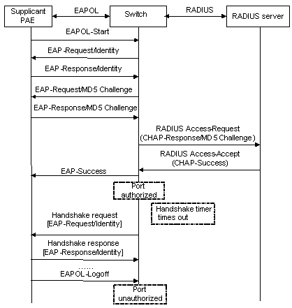
Figure 1-9 802.1x authentication procedure (in EAP termination mode)
The authentication procedure in EAP termination mode is the same as that in the EAP relay mode except that the randomly-generated key in the EAP termination mode is generated by the switch, and that it is the switch that sends the user name, the randomly-generated key, and the supplicant system-encrypted password to the RADIUS server for further authentication.
1.1.5 802.1x Timer
In 802.1 x authentication, the following timers are used to ensure that the supplicant system, the switch, and the RADIUS server interact orderly:
l Transmission timer (tx-period): This timer sets the transmission period and is triggered by the switch in one of the following two cases: The first case is when a supplicant system requests for authentication. The switch sends a unicast request/identity packet to the supplicant system and then enables the transmission timer. The switch will send another request/identity packet to the supplicant system if it has not received any response from the supplicant system when this timer times out. The second case is when the switch authenticates the 802.1x client who does not request for authentication actively. The switch sends multicast request/identity packets continuously through the port with 802.1x enabled at the interval of tx-period value.
l Supplicant system timer (supp-timeout): This timer sets the supp-timeout period and is triggered by the switch after the switch sends a request/challenge packet to a supplicant system. The switch will send another request/challenge packet to the supplicant system if it has not received any response from the supplicant system when this timer times out.
l RADIUS server timer (server-timeout): This timer sets the server-timeout period. The switch will resend the authentication request packet if the RADIUS server does not respond when this timer times out.
l Handshake timer (handshake-period): This timer sets the handshake-period and is triggered after a supplicant system passes the authentication. The switch will resend the handshake request packet to online users at this interval to check their state. If you set the number of retries to N by using the dot1x retry command, an online user is considered offline when the switch has not received response packets from it in N retries.
l Re-authentication timer (reauth-period): Within this timer period, the switch will initialize 802.1x re-authentication.
l Quiet-period timer (quiet-period): This timer sets the quiet-period. When a supplicant system fails to pass the authentication, the switch quiets for a period of time (set by the quiet-period timer) before it processes another authentication request initiated by the supplicant system.
l ver-period: This timer sets the client version request timer. The authenticator system will resend the client version checking request packet if the supplicant system has not responded when this timer times out.
1.1.6 802.1x Implementation on an S7500 Series Switch
In addition to the previously mentioned 802.1x features, an S7500 series switch is also capable of:
l Cooperating with a CAMS server to perform proxy detection, such as detecting login through proxy server and multiple network interface cards;
l Checking client version;
l Implementing the Guest VLAN function.
I. Proxy detection
An S7500 series switch implements 802.1x proxy detection to check:
l A supplicant system logging in through the proxy server;
l A supplicant system logging in through the IE proxy server;
l A supplicant system logging in through multiple network interface cards (that is, more than one network adapter are active in a supplicant system when it logs in).
In response to any of the three cases, a switch can optionally take the following measures:
l Disconnects the supplicant system and sends Trap packets (using the dot1x supp-proxy-check logoff command);
l Sends Trap packets without disconnecting the supplicant system (using the dot1x supp-proxy-check trap command).
This function needs the support of 802.1x clients and CAMS:
l The 802.1x clients are capable of detecting multiple network interface cards, proxy server, or IE proxy server.
l CAMS is capable of disabling multiple network interface cards, proxy sever, or IE proxy server on the supplicant system.
By default, an 802.1x client program disables the function of disabling multiple network interface cards, proxy server, and IE proxy server. If CAMS enables the function, it will prompt the 802.1x client to enable the function after the supplicant system passes the authentication.
& Note:
l The proxy detection function needs the support of H3C’s 802.1x client program.
l The proxy detection function should be enabled on both the 802.1x client program and CAMS. The client version checking function should be enabled on the switch (by using the dot1x version-check command).
II. Client version checking
With the 802.1x client version checking function enabled, a switch will check the version and validity of an 802.1x client to prevent unauthorized users or users with earlier versions of 802.1x from logging in.
The switch will resend a version request packet if the supplicant system does not send a version reply packet to it when the version-checking timer times out.
& Note:
The client version checking function needs the support of H3C’s 802.1x client program.
III. Guest VLAN
The Guest VLAN function enables supplicant systems that do not pass the authentication to access a LAN in a restrained way.
With the Guest VLAN function enabled, supplicant systems that do not have 802.1x client installed can access specific network resources. They can also upgrade their 802.1x clients without being authenticated.
With this function enabled:
l The switch multicasts trigger packets to all 802.1x-enabled ports.
l If some port still does not send any response packet after the retry times reaches the maximum value, the switch will add the port into the Guest VLAN.
l Users belonging to the Guest VLAN can access the resources of the Guest VLAN without being authenticated. But they need to be authenticated before accessing external resources.
Normally, the Guest VLAN function is coupled with the dynamic VLAN assignment function.
For detailed information about dynamic VLAN assignment function, Refer to AAA-RADIUS-HWTACACS-EAD Operation Manual .
1.2 802.1x Configuration
802.1x provides a solution for authenticating users. To implement this solution, you need to execute 802.1x-related commands. You also need to configure AAA schemes on switches and to specify the authentication scheme (RADIUS authentication scheme or local authentication scheme).
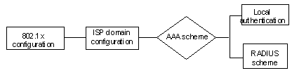
Figure 1-10 802.1x configuration
l 802.1x users use domain names to associate with the ISP domains configured on switches.
l An AAA scheme (a local authentication scheme or the RADIUS scheme) is configured for the ISP domain.
l If you specify to use the RADIUS scheme, that is to say the supplicant systems are authenticated by a remote RADIUS server, you need to configure the related user names and passwords on the RADIUS server and perform RADIUS client-related configuration on the switches.
l If you specify to adopt a local authentication scheme, you need to configure user names and passwords manually on the switches. Users can pass the authentication through the 802.1x client if they provide the user names and passwords that match with those stored in the switches.
l You can also specify to adopt RADIUS authentication scheme, with a local authentication scheme as an alternative. In this case, the local authentication scheme is adopted when the RADIUS server fails.
Refer to AAA-RADIUS-HWTACACS-EAD Operation Manual for detailed information about AAA configuration.
1.3 Basic 802.1x Configuration
To utilize 802.1x features, you need to perform basic 802.1x configuration.
1.3.1 Prerequisites
l Configure ISP domain and its AAA scheme, specify the authentication scheme ( RADIUS or a local scheme) .
l For local authentication scheme, configure the service type of local users as lan-access.
1.3.2 Configuring Basic 802.1x Functions
Table 1-1 Configure basic 802.1x functions
|
To do... |
Use the command... |
Remarks |
|
Enter system view |
system-view |
— |
|
Enable 802.1x globally |
dot1x |
Required Disabled by default |
|
Enable 802.1x for the specified ports |
Use the following command in system view: dot1x [ interface interface-list ] |
Required Disabled by default |
|
Use the following command in port view: dot1x |
||
|
Specify access control mode for the specified ports |
dot1x port-control { authorized-force | unauthorized-force | auto } [ interface interface-list ] |
Optional auto mode by default |
|
Specify access method for the specified ports |
dot1x port-method { macbased | portbased } [ interface interface-list ] |
Optional macbased method by default |
|
Specify authentication method for 802.1x users |
dot1x authentication-method { chap | pap | eap } |
Optional By default, a switch performs CHAP authentication in EAP termination mode. |
|
Enable 802.1x re-authentication |
In system view: dot1x re-authenticate [ interface interface-list ] In port view: dot1x re-authenticate |
Optional Disabled by default |
![]() Caution:
Caution:
l 802.1x-related configurations can all be performed in system view. Port access control mode and port access method can also be configured in port view.
l If you perform a configuration in system view and do not specify the interface-list argument, the configuration applies to all ports. Configurations performed in Ethernet port view apply to the current Ethernet port only and the interface-list argument is not needed in this case.
l 802.1x configurations take effect only after you enable 802.1x both globally and for the specified ports.
l You can enable 802.1x re-authentication on the switch either by using the dot1x re-authenticate command or through the RADIUS server. The switch re-authenticates the user periodically if the Termination-Action attribute value of the Access-Accept packet sent by the authentication server to the switch is set to 1.
1.4 Timer and Maximum User Number Configuration
Table 1-2 Configure 802.1x timers and the maximum number of users
|
To do... |
Use the command... |
Remarks |
|
Enter system view |
system-view |
— |
|
Configure the maximum number of concurrent on-line users for the specified ports |
In system view: dot1x max-user user-number [ interface interface-list ] |
Optional By default, up to 1,024 concurrent on-line users are allowed on each port. |
|
In port view: dot1x max-user user-number |
||
|
Configure the maximum retry times to send a request packet |
dot1x retry max-retry-value |
Optional By default, max-retry-value is 2. That is, the authenticator system is allowed to send a request packet to a supplicant system up to two times. |
|
Configure 802.1x timers |
dot1x timer { handshake-period handshake-period-value | reauth-period reauth-period-value | quiet-period quiet-period-value | tx-period tx-period-value | supp-timeout supp-timeout-value | server-timeout server-timeout-value | ver-period ver-period-value } |
Optional The default values of 802.1x timers are as follows: l handshake-period-value: 15 seconds l reauth-period-value: 3,600 seconds l quiet-period-value: 60 seconds l tx-period-value: 30 seconds l supp-timeout-value: 30 seconds l server-timeout-value: 100 seconds l ver-period-value: 30 seconds |
|
Start the quiet-period timer |
dot1x quiet-period |
Optional By default, the quiet-period timer is disabled. |
& Note:
l As for the dot1x max-user command, if you execute it in system view without specifying the interface-list argument, the command applies to all ports. You can also use this command in port view. In this case, this command applies to the current port only and the interface-list argument is not needed.
l As for the configuration of 802.1x timers, the default values are recommended.
l You can set 802.1x re-authentication timer on the switch either by using the dot1x reauth-period command or through the RADIUS server. Upon receiving an Access-Accept packet, with Termination-Action attribute value set to 1, from the server, the switch performs authentication at an interval of the session-timeout value of the Access-Accept packet. In actual authentication, the switch uses the latest time value obtained as the authentication period.
1.5 Advanced 802.1x Configuration
Advanced 802.1x configurations, as listed below, are all optional.
l CAMS cooperation configuration, including detecting multiple network interface cards or proxy server;
l Client version checking configuration;
l DHCP-triggered authentication;
l Guest VLAN configuration.
1.5.1 Prerequisites
Configuration of basic 802.1x
1.5.2 Configuring Proxy Detection
This function needs the support of 802.1x client program and CAMS, as listed below.
l The 802.1x clients must be able to check a supplicant system uses multiple network cards, proxy server, or IE proxy server to log in.
l CAMS enables the function of disabling multiple network interface cards, proxy server, or IE proxy server on the authenticator system.
By default, the 802.1x client disables the function of disabling multiple network interface cards, proxy server, and IE proxy server. If you specify CAMS to enable the function, CAMS will notify the 802.1x client that it should enable the function when a user passes the authentication.
Table 1-3 Configure proxy detection
|
To do... |
Use the command... |
Remarks |
|
Enter system view |
system-view |
— |
|
Enable the proxy detection function |
dot1x supp-proxy-check { logoff | trap } |
Required Disabled by default |
|
Enable proxy detection for the specified ports |
In system view: dot1x supp-proxy-check { logoff | trap } [ interface interface-list ] |
Required Disabled by default |
|
In port view: dot1x supp-proxy-check { logoff | trap } |
& Note:
l The proxy detection function needs the support of H3C's 802.1x client program.
l The proxy detection function should be enabled on both the 802.1x client program and CAMS. The client version checking should be enabled on the switch (by using the dot1x version-check command).
1.5.3 Configuring Client Version Checking
Table 1-4 Configure client version checking
|
To do... |
Use the command... |
Remarks |
|
Enter system view |
system-view |
— |
|
Enable 802.1x client version checking |
dot1x version-check [ interface interface-list ] |
Required Disabled by default |
|
Configure the maximum number of retry times to send a version checking request packet |
dot1x retry-version-max max-retry-version-value |
Optional 3 by default |
|
Configure the ver-period timer |
dot1x timer ver-period ver-period-value |
Optional The default ver-period-value is 30 seconds |
& Note:
As for the dot1x version-user command, if you execute it in system view without specifying the interface-list argument, the command applies to all ports. You can also use this command in port view. In this case, this command applies to the current port only and the interface-list argument is not needed.
1.5.4 Enabling DHCP-triggered Authentication
With the following configuration, 802.1X allows the authenticator system to authenticate the identity of an access user when the user runs DHCP to apply an IP address dynamically.
Table 1-5 Enable DHCP-triggered authentication
|
To do... |
Use the command... |
Remarks |
|
Enter system view |
system-view |
— |
|
Enable DHCP-triggered authentication |
dot1x dhcp-launch |
Disabled by default |
1.5.5 Configuring Guest VLAN
Table 1-6 Configure Guest VLAN
|
To do... |
Use the command... |
Remarks |
|
Enter system view |
system-view |
— |
|
Configure control access method |
dot1x port-method { macbased | portbased } |
Optional macbased method by default |
|
Enable the Guest VLAN function |
dot1x guest-vlan vlan-id [ interface interface-list ] |
Required Disabled by default |
![]() Caution:
Caution:
l The Guest VLAN function is available only when the switch operates in a port-based authentication mode.
l Only one Guest VLAN can be configured for each switch.
1.6 Displaying and Debugging 802.1x
After performing the above configurations, you can display and verify the 802.1x-related configuration by executing the display command in any view.
You can clear 802.1x-related statistics by executing the reset command in user view.
Table 1-7 Display and debug 802.1x
|
To do... |
Use the command... |
Remarks |
|
Display the configuration, health, and statistics about 802.1x |
display dot1x [ sessions | statistics ] [ interface interface-list ] |
In any view |
|
Clear 802.1x-related statistics information |
reset dot1x statistics [ interface interface-list ] |
In user view |
1.7 Configuration Example
1.7.1 802.1x Configuration Example
I. Network requirements
l Supplicant systems are authenticated on all ports to control their accesses to the Internet. The switch operates in MAC address-based access control mode.
l All supplicant systems that pass the authentication belong to the default domain named aabbcc.net. The domain can accommodate up to 30 users. For authentication, a supplicant system is authenticated locally if the RADIUS server fails. For accounting, a supplicant system is disconnected if the RADIUS server fails. The name of an authenticated supplicant system is not suffixed with the domain name. The switch will tear down the connection to the supplicant system if the traffic is less than 2,000 bytes within 20 minutes.
l The switch is connected to the server group composed of two RADIUS servers whose IP addresses are 10.11.1.1 and 10.11.1.2 respectively. The RADIUS server with an IP address of 10.11.1.1 operates as the primary authentication server and the secondary accounting server. The other operates as the secondary authentication server and the primary accounting server. The password for the switch and the authentication RADIUS servers to exchange message is name. And the password for the switch and the accounting RADIUS servers to exchange message is money. When the switch sends a packet to the RADIUS server but does not receive any response in 5 seconds, it will send the packet to the RADIUS servers again for a maximum number of 5 retries. And the switch sends a real-time accounting packet to the RADIUS servers once in every 15 minutes. A user name is sent to the RADIUS servers with the domain name truncated.
l The user name and password for local 802.1x authentication are localuser and localpass (in plain text) respectively. The idle disconnecting function is enabled.
II. Network diagram
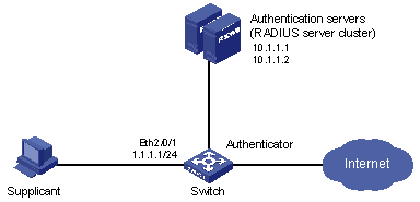
Figure 1-11 Network diagram for AAA configuration with 802.1x and RADIUS enabled
III. Configuration procedure
& Note:
Following configuration covers the major AAA/RADIUS configuration commands. You can refer to AAA-RADIUS-HWTACACS-EAD Operation Manual for information about these commands. Configurations on the client and the RADIUS servers are omitted.
# Enable 802.1x globally.
<H3C> system-view
System View: return to User View with Ctrl+Z.
[H3C] dot1x
# Enable 802.1x for Ethernet 2/0/1.
[H3C] dot1x interface Ethernet 2/0/1
# Set the access control method to MAC-address-based (This command can be omitted as MAC-address-based is the default configuration).
[H3C] dot1x port-method macbased interface Ethernet 2/0/1
# Create a RADIUS scheme named radius1 and enter RADIUS scheme view.
[H3C] radius scheme radius1
# Assign IP addresses to the primary authentication and accounting RADIUS servers.
[H3C-radius-radius1] primary authentication 10.11.1.1
[H3C-radius-radius1] primary accounting 10.11.1.2
# Assign IP addresses to the secondary authentication and accounting RADIUS servers.
[H3C-radius-radius1] secondary authentication 10.11.1.2
[H3C-radius-radius1] secondary accounting 10.11.1.1
# Set the password for the switch and the authentication RADIUS servers to exchange messages.
[H3C -radius-radius1] key authentication name
# Set the password for the switch and the accounting RADIUS servers to exchange messages.
[H3C-radius-radius1] key accounting money
# Set the interval and the number of retries for the switch to send packets to the RADIUS servers.
[H3C-radius-radius1] timer 5
[H3C-radius-radius1] retry 5
# Set the interval and the number of retries for the switch to send real-time accounting packets to the RADIUS servers.
[H3C-radius-radius1] timer realtime-accounting 15
# Configure to send the user name to the RADIUS server with the domain name removed beforehand.
[H3C-radius-radius1] user-name-format without-domain
[H3C-radius-radius1] quit
# Create a domain named aabbcc.net and enter its view.
[H3C] domain enable aabbcc.net
# Adopt radius1 as the RADIUS scheme of the user domain. If the RADIUS server does not work, adopt local authentication scheme.
[H3C-isp-aabbcc.net] scheme radius-scheme radius1 local
# Specify the maximum number of users the user domain can accommodate as 30.
[H3C-isp-aabbcc.net] access-limit enable 30
# Enable the idle disconnecting function and set the related parameters.
[H3C-isp-aabbcc.net] idle-cut enable 20 2000
[H3C-isp-aabbcc.net] quit
# Configure aabbcc.net as the default user domain.
[H3C] domain default enable aabbcc.net
# Create a local access user.
[H3C] local-user localuser
[H3C-luser-localuser] service-type lan-access
[H3C-luser-localuser] password simple localpass
Chapter 2 HABP Configuration
When configuring HABP, go to these sections for information you are interested in:
2.1 Introduction to HABP
With 802.1x enabled, a switch will authenticate and authorize 802.1x-enabled ports. Packets can be forwarded only by authorized ports. If those ports connected to the switch are not authenticated and authorized by 802.1x, all packets will be filtered. This means that users cannot manage the attached switches. Huawei authentication bypass protocol (HABP) can solve this problem.
HABP packets carry the MAC addresses of the attached switches. Once HABP is enabled on the switches, HABP packets will be allowed to bypass 802.1x authentication and travel through the switches. In this way, management devices can obtain the MAC addresses of the attached switches for high efficient management.
HABP is implemented by HABP server and HABP client. Normally, an HABP server sends HABP request packets regularly to HABP clients to collect the MAC addresses of the attached switches. HABP clients will respond to the HABP request packets and forward the HABP request packets to the lower layer switches. The HABP server usually resides on management devices and HABP clients usually reside on the attached switches.
It is recommended to enable HABP for 802.1x-enabled switches for management purpose.
2.2 HABP Server Configuration
With the HABP server launched, a management device sends HABP request packets regularly to the attached switches to collect their MAC addresses. The interval to send HABP request packets is also configured on the management device.
Table 2-1 Configure an HABP server
|
To do... |
Use the command... |
Remarks |
|
Enter system view |
system-view |
— |
|
Enable HABP |
habp enable |
Required Enabled by default |
|
Configure the current switch to be an HABP server |
habp server vlan vlan-id |
Required By default, a switch operates as an HABP client after you enable HABP on the switch, and if you want to use the switch as a management switch, you must configure the switch to be an HABP server. |
|
Configure the interval to send HABP request packets |
habp timer interval |
Optional 20 seconds by default |
2.3 HABP Client Configuration
HABP clients reside on the switches attached to the HABP server. After you enable HABP on a switch, the switch operates as an HABP client by default. So you only need to enable HABP on a switch.
Table 2-2 Configure an HABP client
|
To do... |
Use the command... |
Remarks |
|
Enter system view |
system-view |
— |
|
Enable HABP |
habp enable |
Optional Enabled by default A switch operates as an HABP client after you enable HABP on it. |
2.4 Displaying HABP
After performing the above configuration, you can display and verify HABP configuration by executing the display command in any view.
|
To do... |
Use the command... |
Remarks |
|
Display information about HABP configuration and status |
display habp |
In any view |
|
Display information about the MAC address table maintained by HABP |
display habp table |
|
|
Display statistics of HABP packets |
display habp traffic |