- Table of Contents
-
- H3C S7500 Series Operation Manual(Release 3100 Series)-(V1.04)
- 00-1Cover
- 00-2Overview
- 01-CLI Configuration
- 02-Login Configuration
- 03-Configuration File Management Configuration
- 04-VLAN Configuration
- 05-Extended VLAN Application Configuration
- 06-IP Address-IP Performance-IPX Configuration
- 07-GVRP Configuration
- 08-QinQ Configuration
- 09-Port Basic Configuration
- 10-Link Aggregation Configuration
- 11-Port Isolation Configuration
- 12-Port Binding Configuration
- 13-DLDP Configuration
- 14-MAC Address Table Configuration
- 15-MSTP Configuration
- 16-Routing Protocol Configuration
- 17-Multicast Configuration
- 18-802.1x Configuration
- 19-AAA-RADIUS-HWTACACS-EAD Configuration
- 20-Traffic Accounting Configuration
- 21-VRRP-HA Configuration
- 22-ARP Configuration
- 23-DHCP Configuration
- 24-ACL Configuration
- 25-QoS Configuration
- 26-Mirroring Configuration
- 27-Cluster Configuration
- 28-PoE Configuration
- 29-UDP-Helper Configuration
- 30-SNMP-RMON Configuration
- 31-NTP Configuration
- 32-SSH Terminal Service Configuration
- 33-File System Management Configuration
- 34-FTP and TFTP Configuration
- 35-Information Center Configuration
- 36-DNS Configuration
- 37-System Maintenance and Debugging Configuration
- 38-HWPing Configuration
- 39-RRPP Configuration
- 40-NAT-Netstream-Policy Routing Configuration
- 41-Telnet Protection Configuration
- 42-Hardware-Dependent Software Configuration
- Related Documents
-
| Title | Size | Download |
|---|---|---|
| 09-Port Basic Configuration | 134 KB |
Table of Contents
Chapter 1 Port Basic Configuration
1.1 Ethernet Port Configuration
1.1.1 Initially Configuring a Port
1.1.2 Configuring Broadcast/Multicast Suppression
1.1.3 Enabling Flow Control on a Port
1.1.4 Copying the Configuration of a Port to Other Ports
1.1.5 Configuring Loopback Detection for a Port
1.1.6 Enabling the System to Test Connected Cable
1.1.7 Configuring the Interval to Perform Statistical Analysis on Port Traffic
1.1.8 Setting Speedup for a Port
1.1.9 Displaying and Maintaining Basic Port Configuration
1.2 Ethernet Port Configuration Example
1.3 Troubleshooting Ethernet Port Configuration
Chapter 1 Port Basic Configuration
When configuring port basic configuration, go to these sections for information you are interested in:
l Ethernet Port Configuration Example
l Troubleshooting Ethernet Port Configuration
1.1 Ethernet Port Configuration
1.1.1 Initially Configuring a Port
|
To do… |
Use the command… |
Remarks |
|
Enter system view |
system-view |
— |
|
Enter Ethernet port view |
interface interface-type interface-number |
— |
|
Enable the Ethernet port |
undo shutdown |
Optional By default, the port is enabled. Use the shutdown command to disable the port. |
|
Set the description of the Ethernet port |
description text |
Optional By default, no description is defined for the port. |
|
Set the duplex mode of the Ethernet port |
duplex { auto | full | half } |
Optional By default, the duplex mode of the port is auto (auto-negotiation). |
|
Set the speed of the Ethernet port |
speed { 10 | 100 | 1000 | 10000 | auto } |
Optional By default, the speed of the port is auto (auto-negotiation). |
|
Set the medium dependent interface (MDI) attribute of the Ethernet port |
mdi { across | auto | normal } |
Optional Be default, the MDI attribute of the port is auto. |
|
Allow jumbo frames to pass through the Ethernet port |
jumboframe enable [ jumboframe-value ] |
Optional By default, jumbo frames that are larger than 1518 bytes and smaller than 1536 bytes are allowed to pass through the port. |
Pay attention to the following points when setting the duplex mode and speed of an Ethernet port.
Table 1-1 Precautions in duplex mode setting
|
Port type |
Precautions in duplex mode setting |
|
100 Mbps electrical Ethernet port |
It can work in full-duplex mode, half-duplex mode or auto-negotiation mode as required. |
|
Gigabit electrical Ethernet port |
It can work in full-duplex mode, half-duplex mode or auto-negotiation mode. However, if the speed is set to 1000 Mbps, its duplex mode can be set to full or auto. |
|
100 Mbps optical Ethernet port |
It works in full-duplex mode and its duplex mode can be set to full or auto. |
|
Gigabit optical Ethernet port |
It works in full-duplex mode and its duplex mode can be set to full or auto. |
|
10,000 Mbps optical Ethernet port |
Its duplex mode can be set to full only. |
|
Management Ethernet port |
Its duplex mode cannot be set. (About this port, refer to S7500 Series Ethernet Switches Installation Manual for detailed information) |
Table 1-2 Precautions in port speed setting
|
Port type |
Precautions in duplex mode setting |
|
100 Mbps electrical Ethernet port |
Its speed can be set to 10 Mbps or 100 Mbps as required. |
|
Gigabit electrical Ethernet port |
Its speed can be set to 10 Mbps, 100 Mbps or 1000 Mbps as required. If its duplex mode is set to full or half, its speed cannot be set to 1000 Mbps. |
|
100 Mbps optical Ethernet port |
Its supports the speed of 100 Mbps. Its speed can be set to 100 Mbps or auto. |
|
Gigabit optical Ethernet port |
Its supports the speed of 1000 Mbps. Its speed can be set to 1000 Mbps or auto. |
|
10,000 Mbps optical Ethernet port |
Its speed can be set to 10,000 Mbps only. |
|
Management Ethernet port |
Its speed cannot be set. |
1.1.2 Configuring Broadcast/Multicast Suppression
By performing the following configurations, you can limit different types of incoming traffic on individual port. When a type of incoming traffic exceeds the threshold you set, the system drops the packets exceeding the traffic limit to reduce the traffic ratio of this type to the reasonable range, so as to keep normal network service.
Follow these steps to configure broadcast/multicast suppression:
|
To do… |
Use the command… |
Remarks |
|
Enter system view |
system-view |
— |
|
Enter Ethernet port view |
interface interface-type interface-number |
— |
|
Limit broadcast traffic received on the current port |
broadcast-suppression { ratio | bandwidth bandwidth | pps pps } |
Optional By default, the switch does not suppress broadcast traffic. |
|
Limit multicast traffic received on the current port |
multicast-suppression { ratio | bandwidth { mbps-value | kbps kbps-value } | pps max-pps } |
Optional By default, the switch does not suppress multicast traffic. |
& Note:
l Broadcast suppression is set in different ways for different LPUs of the S7500 series switches: For type-A LPUs, broadcast suppression must be set in VLAN view; for non-type-A LPUs, broadcast suppression must be set in Ethernet port view.
l Type-A LPUs include LS81FT48A, LS81FM24A, LS81FS24A, LS81GB8UA, and LS81GT8UA.
1.1.3 Enabling Flow Control on a Port
When flow control is enabled on both the local and peer switches, if congestion occurs on the local switch:
l The local switch sends a message to notice the peer switch to stop sending packets to the local switch or reduce the packet sending speed temporarily.
l The peer switch will stop sending packets to the local switch or reduce the sending speed when it receives the message. In this way, packet loss is avoided and the network service operates normally.
Follow these steps to enable flow control on a port:
|
To do… |
Use the command… |
Remarks |
|
Enter system view |
system-view |
— |
|
Enable flow control globally |
flow-control enable |
Required By default, flow control is disabled globally. |
|
Enter Ethernet port view |
interface interface-type interface-number |
— |
|
Enable flow control on the Ethernet port |
flow-control |
Required By default, flow control is disabled on a port. |
1.1.4 Copying the Configuration of a Port to Other Ports
To make some other ports have the same configuration as that of a specific port, you can copy the configuration of the specific port to the ports by using the copy configuration command.
The following types of port configuration can be copied from one port to other ports: VLAN configuration, protocol-based VLAN configuration, LACP configuration, QoS configuration, STP configuration and initial port configuration.
l VLAN configuration: IDs of the VLANs allowed on the port and the default VLAN ID of the port;
l Protocol-based VLAN configuration: IDs and indexes of the protocol-based VLANs allowed on the port;
l Link aggregation control protocol (LACP) configuration: LACP enabled/disabled status;
l QoS configuration: rate limit, port priority, and default 802.1p priority on the port;
l STP configuration: STP enabled/disabled status on the port, link attribute on the port (point-to-point or non-point-to-point), STP priority, path cost, packet transmission rate limit, whether loop guard is enabled, whether root guard is enabled, and whether the port is an edge port;
l Port configuration: link type of the port, port speed and duplex mode.
Follow these steps to copy the configuration of a port to other ports:
|
To do… |
Use the command… |
Remarks |
|
Enter system view |
system-view |
— |
|
Copy the configuration of a port to other ports |
copy configuration source { interface-type interface-number | aggregation-group source-agg-id } destination { interface-list [ aggregation-group destination-agg-id ] | aggregation-group destination-agg-id } |
Required |
& Note:
l If you specify a source aggregation group ID, the system will use the port with the smallest port number in the aggregation group as the source.
l If you specify a destination aggregation group ID, the configuration of the source port will be copied to all ports in the aggregation group and thus all ports in the group will have the same configuration as that of the source port.
1.1.5 Configuring Loopback Detection for a Port
Loopback detection is used to monitor if loopback occurs on a port.
After you enable loopback detection on Ethernet ports, the switch can monitor if external loopback occurs on them. If there is a loopback port found, the switch will put it under control.
l If loopback is found on an access port, the system disables the port, sends a Trap message to the terminal and removes the corresponding MAC address forwarding entry.
l If loopback is found on a trunk or hybrid port, the system disables the port, sends a Trap message to the terminal and removes the corresponding MAC address forwarding entry.
Follow these steps to configure loopback detection for a port:
|
To do… |
Use the command… |
Remarks |
|
Enter system view |
system-view |
— |
|
Enable loopback detection globally |
loopback-detection enable |
Optional By default, loopback detection is disabled globally. |
|
Set the time interval for port loopback detection |
loopback-detection interval-time time |
Optional The default interval is 30 seconds. |
1.1.6 Enabling the System to Test Connected Cable
You can enable the system to test the cable connected to a specific Ethernet electrical port. The test result will be returned in five seconds. The system can test whether there is short circuit/open circuit on the RX and TX directions of the cable, and the length of the faulty cable.
Follow these steps to enable the system to test the cable connected to a specific port:
|
To do… |
Use the command… |
Remarks |
|
Enter system view |
system-view |
— |
|
Enter Ethernet port view |
interface interface-type interface-number |
— |
|
Enable the system to test the cable connected to the port |
virtual-cable-test |
Required |
1.1.7 Configuring the Interval to Perform Statistical Analysis on Port Traffic
By performing the following configuration, you can set the interval to perform statistical analysis on the traffic of a port.
When you use the display interface interface-type interface-number command to display the information of a port, the system displays the average rates of the traffic flow passing through the port during the specified interval. For example, if you set this interval to 100 seconds, the displayed information is as follows:
Last 100 seconds input: 0 packets/sec 0 bytes/sec
Last 100 seconds output: 0 packets/sec 0 bytes/sec
Follow these steps to set the interval to perform statistical analysis on port traffic:
|
To do… |
Use the command… |
Remarks |
|
Enter system view |
system-view |
— |
|
Enter Ethernet port view |
interface interface-type interface-number |
— |
|
Set the interval to perform statistical analysis on port traffic |
flow-interval interval |
Optional By default, this interval is 300 seconds. |
1.1.8 Setting Speedup for a Port
Follow these steps to set speedup for a port:
|
To do… |
Use the command… |
Remarks |
|
Enter system view |
system-view |
— |
|
Enable the hardware speedup function inside the port |
hardspeedup enable |
Optional By default, the hardware speedup function inside the port is enabled. |
|
Disable the hardware speedup function inside the port |
hardspeedup disable |
|
|
Enable the hardware speedup function outside the port |
speedup enable |
Optional By default, the hardware speedup function outside the port is enabled. |
|
Disable the hardware speedup function outside the port |
speedup disable |
![]() Caution:
Caution:
l The hardspeedup enable/disable commands are applicable to type-A LPUs only, including LS81FT48A, LS81FM24A, LS81FS24A, LS81GB8UA, and LS81GT8UA.
l The speedup enable/disable commands are applicable to non-type-A LPUs only.
l The commands above are diagnostic, so you cannot use them at discretion.
1.1.9 Displaying and Maintaining Basic Port Configuration
|
To do… |
Use the command… |
Remarks |
|
Display port configuration information |
display interface [ interface-type | interface-type interface-number ] |
Available in any view. |
|
Display the information about port loopback detection |
display loopback-detection |
|
|
Display brief information about port configuration |
display brief interface [ interface-type interface-number ] [ | { begin | include | exclude } string ] |
|
|
Display the hybrid or trunk ports |
display port { hybrid | trunk } |
|
|
Display port information about the specified unit |
display unit unit-id interface |
|
|
Clear port statistics |
reset counters interface [ interface-type | interface-type interface-number ] |
Available in user view. After 802.1x is enabled on a port, statistics on the port cannot be cleared by the command. |
1.2 Ethernet Port Configuration Example
I. Network requirements
l Switch A and Switch B are connected to each other through two trunk ports (Ethernet 2/0/1).
l Configure the default VLAN ID of both Ethernet 2/0/1 to 100.
l Allow the packets of VLAN 2, VLAN 6 through VLAN 50 and VLAN 100 to pass both Ethernet 2/0/1.
II. Network diagram
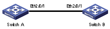
Figure 1-1 Network diagram for Ethernet port configuration
III. Configuration procedure
& Note:
l Only the configuration for Switch A is listed below. The configuration for Switch B is similar to that of Switch A.
l This example supposes that VLAN 2, VLAN 6 through VLAN 50 and VLAN 100 have been created.
# Enter Ethernet port view of Ethernet 2/0/1.
<H3C> system-view
System View: return to User View with Ctrl+Z.
[H3C] interface ethernet2/0/1
# Set Ethernet 2/0/1 as a trunk port.
[H3C-Ethernet2/0/1] port link-type trunk
# Allow packets of VLAN 2, VLAN 6 through VLAN 50 and VLAN 100 to pass Ethernet 2/0/1.
[H3C-Ethernet2/0/1] port trunk permit vlan 2 6 to 50 100
# Configure the default VLAN ID of Ethernet 2/0/1 to 100.
[H3C-Ethernet2/0/1] port trunk pvid vlan 100
1.3 Troubleshooting Ethernet Port Configuration
Symptom: Fail to configure the default VLAN ID of a port.
Solution: Take the following steps.
l Use the display interface or display port command to check if the port is a trunk port or a hybrid port. If not, configure it to a trunk port or a hybrid port.
l Configure the default VLAN ID.