- Table of Contents
-
- H3C S7500 Series Operation Manual(Release 3100 Series)-(V1.04)
- 00-1Cover
- 00-2Overview
- 01-CLI Configuration
- 02-Login Configuration
- 03-Configuration File Management Configuration
- 04-VLAN Configuration
- 05-Extended VLAN Application Configuration
- 06-IP Address-IP Performance-IPX Configuration
- 07-GVRP Configuration
- 08-QinQ Configuration
- 09-Port Basic Configuration
- 10-Link Aggregation Configuration
- 11-Port Isolation Configuration
- 12-Port Binding Configuration
- 13-DLDP Configuration
- 14-MAC Address Table Configuration
- 15-MSTP Configuration
- 16-Routing Protocol Configuration
- 17-Multicast Configuration
- 18-802.1x Configuration
- 19-AAA-RADIUS-HWTACACS-EAD Configuration
- 20-Traffic Accounting Configuration
- 21-VRRP-HA Configuration
- 22-ARP Configuration
- 23-DHCP Configuration
- 24-ACL Configuration
- 25-QoS Configuration
- 26-Mirroring Configuration
- 27-Cluster Configuration
- 28-PoE Configuration
- 29-UDP-Helper Configuration
- 30-SNMP-RMON Configuration
- 31-NTP Configuration
- 32-SSH Terminal Service Configuration
- 33-File System Management Configuration
- 34-FTP and TFTP Configuration
- 35-Information Center Configuration
- 36-DNS Configuration
- 37-System Maintenance and Debugging Configuration
- 38-HWPing Configuration
- 39-RRPP Configuration
- 40-NAT-Netstream-Policy Routing Configuration
- 41-Telnet Protection Configuration
- 42-Hardware-Dependent Software Configuration
- Related Documents
-
| Title | Size | Download |
|---|---|---|
| 02-Login Configuration | 568 KB |
Table of Contents
Chapter 1 Logging into an Ethernet Switch
1.1 Logging into an Ethernet Switch
1.2 Introduction to the User Interface
1.2.1 Supported User Interfaces
1.2.3 Common User Interface Configuration
Chapter 2 Logging in through the Console Port
2.2 Logging in through the Console Port
2.3 Console Port Login Configuration
2.3.2 Console Port Login Configurations for Different Authentication Modes
2.4 Console Port Login Configuration with Authentication Mode Being None
2.5 Console Port Login Configuration with Authentication Mode Being Password
2.6 Console Port Login Configuration with Authentication Mode Being Scheme
Chapter 3 Logging in through Telnet
3.1.2 Telnet Configurations for Different Authentication Modes
3.2 Telnet Configuration with Authentication Mode Being None
3.3 Telnet Configuration with Authentication Mode Being Password
3.4 Telnet Configuration with Authentication Mode Being Scheme
3.5.1 Telneting to a Switch from a Terminal
3.5.2 Telneting to Another Switch from the Current Switch
Chapter 4 Logging in Using Modem
4.2 Configuration on the Administrator Side
4.3 Configuration on the Switch Side
4.4 Modem Connection Establishment
4.5 Modem Attributes Configuration
4.5.1 Configuration Prerequisites
Chapter 5 Logging in through NMS
5.2 Connection Establishment Using NMS
6.2.1 Controlling Telnet Users by Source IP Addresses
6.2.2 Controlling Telnet Users by Source and Destination IP Addresses
6.3 Controlling Network Management Users by Source IP Addresses
6.3.2 Controlling Network Management Users by Source IP Addresses
Chapter 1 Logging into an Ethernet Switch
When configuring logging into an Ethernet switch, go to these sections for information you are interested in:
l Logging into an Ethernet Switch
l Introduction to the User Interface
1.1 Logging into an Ethernet Switch
You can log into an S7500 series Ethernet switch in one of the following ways:
l Logging in locally through the console port
l Telneting locally or remotely to an Ethernet port
l Telneting to the console port using a Modem
l Logging in through network management station (NMS)
1.2 Introduction to the User Interface
1.2.1 Supported User Interfaces
S7500 series Ethernet switches support two types of user interfaces: AUX and VTY.
Table 1-1 Description on user interfaces
|
User interface |
Applicable user |
Port used |
Description |
|
AUX |
Users logging in through the console port |
console port |
Each switch can accommodate one AUX user. |
|
VTY |
Telnet users and SSH users |
Ethernet port |
Each switch can accommodate up to five VTY users. |
& Note:
The AUX port and the console port of an H3C series switch are the same port. You will be in the AUX user interface if you log in through this port.
1.2.2 User Interface Number
Two kinds of user interface indexes exist: absolute user interface indexes and relative user interface indexes.
1) The absolute user interface indexes are as follows:
l AUX user interface: 0
l VTY user interfaces: Numbered after the AUX user interface. The absolute index of the first VTY user interface is greater than that of the AUX user interface by 1 and the following VTY user interface indexes increase in the step of 1
2) A relative user interface index can be obtained by appending a number to the identifier of a user interface type. It is generated by user interface type. The relative user interface indexes are as follows:
l AUX user interface: AUX 0
l VTY user interfaces: VTY 0, VTY 1, VTY 2, and so on.
1.2.3 Common User Interface Configuration
|
To do… |
Use the command… |
Remarks |
|
Lock the current user interface |
lock |
Optional Execute this command in user view. A user interface is not locked by default. |
|
Specify to send messages to all user interfaces/a specified user interface |
send { all | number | type number } |
Optional Execute this command in user view. |
|
Disconnect a specified user interface |
free user-interface [ type ] number |
Optional Execute this command in user view. |
|
Enter system view |
system-view |
— |
|
Enter user interface view |
user-interface [ type ] first-number [ last-number ] |
— |
|
Set the command that is automatically executed when a user logs into the user interface |
auto-execute command text |
Optional By default, no command is automatically executed when a user logs into a user interface. |
|
Display the information about the current user interface/all user interfaces |
display users [ all ] |
Optional These two commands can be executed in any view. |
|
Display the physical attributes and configuration of the current/a specified user interface |
display user-interface [ type number | number ] |
l The auto-execute command command may cause you unable to perform common configuration in the user interface, so use it with caution.
l Before configuring the auto-execute command command and saving the configuration, make sure you can log into the switch in other ways to cancel the configuration.
Chapter 2 Logging in through the Console Port
When logging into a switch through its console port, go to these sections for information you are interested in:
l Logging in through the Console Port
l Console Port Login Configuration
l Console Port Login Configuration with Authentication Mode Being None
l Console Port Login Configuration with Authentication Mode Being Password
l Console Port Login Configuration with Authentication Mode Being Scheme
2.1 Introduction
To log in through the console port is the most common way to log into a switch. It is also the prerequisite to configure other login methods. By default, you can log into an S7500 series Ethernet switch locally through its console port.
To log into an Ethernet switch through its console port, the communication configuration of the user terminal must be in accordance with that of the console port.
Table 2-1 lists the default settings of a console port.
Table 2-1 The default settings of a console port
|
Setting |
Default |
|
Baud rate |
9,600 bps |
|
Flow control |
None |
|
Check mode (Parity) |
None |
|
Stop bits |
1 |
|
Data bits |
8 |
After logging into a switch, you can perform configuration for AUX users. Refer to section Console Port Login Configuration for more.
2.2 Logging in through the Console Port
Following are the procedures to connect to a switch through the console port.
1) Connect the serial port of your PC/terminal to the console port of the switch, as shown in Figure 2-1.
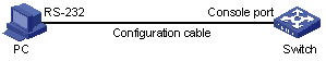
Figure 2-1 Diagram for setting the connection to the console port
2) If you use a PC to connect to the console port, launch a terminal emulation program (such as Terminal in Windows 3.X or HyperTerminal in Windows 9X), choose the serial port to be connected to the switch and perform the configuration shown in Figure 2-2 through Figure 2-4 for the connection to be created. Normally, the parameters of a terminal are configured as those listed in Table 2-1. And the type of the terminal is set to VT100.
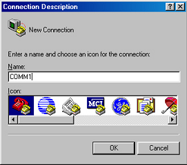
Figure 2-2 Create a connection

Figure 2-3 Specify the port used to establish the connection

Figure 2-4 Set port parameters
3) Power on the switch. You will be prompted to press the Enter key if the switch successfully completes POST (power-on self test). The prompt (such as <H3C>) appears after you press the Enter key.
4) You can then configure the switch or check the information about the switch by executing the corresponding commands. You can also acquire help by type the ? character. The commands available on a switch are described in the command manuals.
2.3 Console Port Login Configuration
2.3.1 Common Configuration
Table 2-2 lists the common configuration of console port login.
Table 2-2 Common configuration of console port login
|
Configuration |
Remarks |
|
|
Console port configuration |
Baud rate |
Optional The default baud rate is 9,600 bps. |
|
Check mode |
Optional By default, the check mode of the console port is set to none, which means no check bit. |
|
|
Stop bits |
Optional The default stop bits of a console port is 1. |
|
|
Data bits |
Optional The default data bits of a console port is 8. |
|
|
AUX user interface configuration |
Configure the command level available to the users logging into the AUX user interface |
Optional By default, commands of level 3 are available to the users logging into the AUX user interface. |
|
Terminal configuration |
Make terminal services available |
Optional By default, terminal services are available in all user interfaces |
|
Set the maximum number of lines the screen can contain |
Optional By default, the screen can contain up to 24 lines. |
|
|
Set history command buffer size |
Optional By default, the history command buffer can contain up to 10 commands. |
|
|
Set the timeout time of a user interface |
Optional The default timeout time is 10 minutes. |
|
![]() Caution:
Caution:
Changing of console port configuration terminates the connection to the console port. To establish the connection again, you need to modify the configuration of the terminal emulation program running on your PC accordingly. Refer to Figure 2-4 for the configuration.
2.3.2 Console Port Login Configurations for Different Authentication Modes
Table 2-3 lists console port login configurations for different authentication modes.
Table 2-3 Console port login configurations for different authentication modes
|
Authentication mode |
Console port login configuration |
Remarks |
|
|
None |
Perform common configuration |
Perform common configuration for console port login |
Optional Refer to Table 2-2 for detail. |
|
Password |
Configure the password |
Configure the password for local authentication |
Required |
|
Perform common configuration |
Perform common configuration for console port login |
Optional Refer to Table 2-2 for detail. |
|
|
Scheme |
Specify to perform local authentication or RADIUS authentication |
AAA configuration specifies whether to perform local authentication or RADIUS authentication |
Optional Local authentication is performed by default. Refer to the AAA&RADIUS&HWTACACS&EAD module for more. |
|
Configure user name and password |
Configure user names and passwords for local/RADIUS users |
Required l The user name and password of a local user are configured on the switch. l The user name and password of a RADIUS user are configured on the RADIUS server. Refer to user manual of RADIUS server for more. |
|
|
Manage AUX users |
Set service type for AUX users |
Required |
|
|
Perform common configuration |
Perform common configuration for console port login |
Optional Refer to Table 2-2 for detail. |
|
& Note:
Changes of the authentication mode of console port login will not take effect immediately. The changes take effect after you quit the command-line interface and then enter it again.
2.4 Console Port Login Configuration with Authentication Mode Being None
2.4.1 Configuration Procedure
Follow these steps to perform the console port login configuration with the authentication mode being none:
|
To do… |
Use the command… |
Remarks |
|
|
Enter system view |
system-view |
— |
|
|
Enter AUX user interface view |
user-interface aux 0 |
— |
|
|
Configure not to authenticate users |
authentication-mode none |
Required By default, users logging in through the console port need not to be authenticated. |
|
|
Configure the console port |
Set the baud rate |
speed speed-value |
Optional The default baud rate of an AUX port (also the console port) is 9,600 bps. |
|
Set the check mode |
parity { even | mark | none | odd | space } |
Optional By default, the check mode of a console port is set to none, that is, no check bit. |
|
|
Set the flow control mode |
flow-control { hardware | none | software } |
Optional By default, a console port does not perform flow control. |
|
|
Set the stop bits |
stopbits { 1 | 1.5 | 2 } |
Optional The stop bits of a console port is 1. |
|
|
Set the data bits |
databits { 7 | 8 } |
Optional The default data bits of a console port is 8. |
|
|
Configure the command level available to users logging into the user interface |
user privilege level level |
Optional By default, commands of level 3 are available to users logging into the AUX user interface. |
|
|
Make terminal services available |
shell |
Optional By default, terminal services are available in all user interfaces. |
|
|
Set the maximum number of lines the screen can contain |
screen-length screen-length |
Optional By default, the screen can contain up to 24 lines. You can use the screen-length 0 command to disable the function of displaying information in pages. |
|
|
Set the history command buffer size |
history-command max-size value |
Optional The default history command buffer size is 10. That is, a history command buffer can store up to 10 commands by default. |
|
|
Set the timeout time for the user interface |
idle-timeout minutes [ seconds ] |
Optional The default timeout time of a user interface is 10 minutes. With the timeout time being 10 minutes, the connection to a user interface is terminated if no operation is performed in the user interface within 10 minutes. You can use the idle-timeout 0 command to disable the timeout function. |
|
Note that the command level available to users logging into a switch depends on both the authentication-mode none command and the user privilege level level command, as listed in the following table.
Table 2-4 Determine the command level
|
Scenario |
Command level |
||
|
Authentication mode |
User type |
Command configuration |
|
|
None (authentication-mode none) |
Users logging in through console ports |
The user privilege level level command is not executed |
Level 3 |
|
The user privilege level level command is already executed |
Determined by the level argument |
||
2.4.2 Configuration Example
I. Network requirements
Assume that you are a level 3 VTY user and want to perform the following configuration for users logging in through the console port:
l Do not authenticate users logging in through the console port.
l Commands of level 2 are available to users logging into the AUX user interface.
l The baud rate of the console port is 19,200 bps.
l The screen can contain up to 30 lines.
l The history command buffer can contain up to 20 commands.
l The timeout time of the AUX user interface is 6 minutes.
II. Network diagram
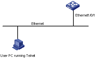
Figure 2-5 Network diagram for AUX user interface configuration (with the authentication mode being none)
III. Configuration procedure
# Enter system view.
<H3C> system-view
# Enter AUX user interface view.
[H3C] user-interface aux 0
# Specify not to authenticate users logging in through the console port.
[H3C-ui-aux0] authentication-mode none
# Specify commands of level 2 are available to users logging into the AUX user interface.
[H3C-ui-aux0] user privilege level 2
# Set the baud rate of the console port to 19,200 bps.
[H3C-ui-aux0] speed 19200
# Set the maximum number of lines the screen can contain to 30.
[H3C-ui-aux0] screen-length 30
# Set the maximum number of commands the history command buffer can store to 20.
[H3C-ui-aux0] history-command max-size 20
# Set the timeout time of the AUX user interface to 6 minutes.
[H3C-ui-aux0] idle-timeout 6
2.5 Console Port Login Configuration with Authentication Mode Being Password
2.5.1 Configuration Procedure
Follow these steps to perform console port login configuration with the authentication mode being password:
|
To do… |
Use the command… |
Remarks |
|
|
Enter system view |
system-view |
— |
|
|
Enter AUX user interface view |
user-interface aux 0 |
— |
|
|
Configure to authenticate users using the local password |
authentication-mode password |
Required By default, users logging into a switch through the console port are not authenticated; while those logging in through Modems or Telnet are authenticated. |
|
|
Set the local password |
set authentication password { cipher | simple } password |
Required |
|
|
Configure the console port |
Set the baud rate |
speed speed-value |
Optional The default baud rate of an AUX port (also the console port) is 9,600 bps. |
|
Set the check mode |
parity { even | mark | none | odd | space } |
Optional By default, the check mode of a console port is set to none, that is, no check bit. |
|
|
Set the flow control mode |
flow-control { hardware | none | software } |
Optional By default, a console port does not perform flow control. |
|
|
Set the stop bits |
stopbits { 1 | 1.5 | 2 } |
Optional The default stop bits of a console port is 1. |
|
|
Set the data bits |
databits { 7 | 8 } |
Optional The default data bits of a console port is 8. |
|
|
Configure the command level available to users logging into the user interface |
user privilege level level |
Optional By default, commands of level 3 are available to users logging into the AUX user interface. |
|
|
Make terminal services available to the user interface |
shell |
Optional By default, terminal services are available in all user interfaces. |
|
|
Set the maximum number of lines the screen can contain |
screen-length screen-length |
Optional By default, the screen can contain up to 24 lines. You can use the screen-length 0 command to disable the function of displaying information in pages. |
|
|
Set history command buffer size |
history-command max-size value |
Optional The default history command buffer size is 10. That is, a history command buffer can store up to 10 commands by default. |
|
|
Set the timeout time for the user interface |
idle-timeout minutes [ seconds ] |
Optional The default timeout time of a user interface is 10 minutes. With the timeout time being 10 minutes, the connection to a user interface is terminated if no operation is performed in the user interface within 10 minutes. You can use the idle-timeout 0 command to disable the timeout function. |
|
Note that the level the commands of which are available to users logging into a switch depends on both the authentication-mode password and the user privilege level level command, as listed in the following table.
Table 2-5 Determine the command level
|
Scenario |
Command level |
||
|
Authentication mode |
User type |
Command configuration |
|
|
Local password authentication (authentication-mode password) |
Users logging in through the AUX user interface |
The user privilege level level command is not executed |
Level 3 |
|
The user privilege level level command is already executed |
Determined by the level argument |
||
2.5.2 Configuration Example
I. Network requirements
Assume that you are a level 3 VTY user and want to perform the following configuration for users logging in through the console port:
l Authenticate users logging in through the console port using the local password.
l Set the local password to 123456 (in plain text).
l The commands of level 2 are available to users logging into the AUX user interface.
l The baud rate of the console port is 19,200 bps.
l The screen can contain up to 30 lines.
l The history command buffer can store up to 20 commands.
l The timeout time of the AUX user interface is 6 minutes.
II. Network diagram
Figure 2-6 Network diagram for AUX user interface configuration (with the authentication mode being password)
III. Configuration procedure
# Enter system view.
<H3C> system-view
# Enter AUX user interface view.
[H3C] user-interface aux 0
# Specify to authenticate users logging in through the console port using the local password.
[H3C-ui-aux0] authentication-mode password
# Set the local password to 123456 (in plain text).
[H3C-ui-aux0] set authentication password simple 123456
# Specify commands of level 2 are available to users logging into the AUX user interface.
[H3C-ui-aux0] user privilege level 2
# Set the baud rate of the console port to 19,200 bps.
[H3C-ui-aux0] speed 19200
# Set the maximum number of lines the screen can contain to 30.
[H3C-ui-aux0] screen-length 30
# Set the maximum number of commands the history command buffer can store to 20.
[H3C-ui-aux0] history-command max-size 20
# Set the timeout time of the AUX user interface to 6 minutes.
[H3C-ui-aux0] idle-timeout 6
2.6 Console Port Login Configuration with Authentication Mode Being Scheme
2.6.1 Configuration Procedure
Follow these steps to perform console port login configuration with the authentication mode being scheme:
|
To do… |
Use the command… |
Remarks |
||
|
Enter system view |
system-view |
— |
||
|
Configure the authentication mode |
Enter the default ISP domain view |
domain domain-name |
Optional By default, the local AAA scheme is applied. If you specify to apply the local AAA scheme, you need to perform the configuration concerning local user as well. If you specify to apply an existing scheme by providing the radius-scheme-name argument, you need to perform the following configuration as well: l Perform AAA&RADIUS configuration on the switch. (Refer to the AAA&RADIUS&HWTACACS&EAD module for more.) l Configure the user name and password accordingly on the AAA server. (Refer to the user manual of AAA server.) |
|
|
Specify the AAA scheme to be applied to the domain |
scheme { local | radius-scheme radius-scheme-name [ local ] | none } |
|||
|
Return to system view |
quit |
|||
|
Create a local user (Enter local user view.) |
local-user user-name |
Required No local user exists by default. |
||
|
Set the authentication password for the local user |
password { simple | cipher } password |
Required |
||
|
Specify the service type for AUX users |
service-type terminal [ level level ] |
Required |
||
|
Return to system view |
quit |
— |
||
|
Enter AUX user interface view |
user-interface aux 0 |
— |
||
|
Configure to authenticate users locally or remotely using user name and password |
authentication-mode scheme [ command- authorization ] |
Required The specified AAA scheme determines whether to authenticate users locally or remotely. Users are authenticated locally by default. |
||
|
Configure the console port |
Set the baud rate |
speed speed-value |
Optional The default baud rate of the AUX port (also the console port) is 9,600 bps. |
|
|
Set the check mode |
parity { even | mark | none | odd | space } |
Optional By default, the check mode of a console port is set to none, that is, no check bit. |
||
|
Set the flow control mode |
flow-control { hardware | none | software } |
Optional By default, a console port does not perform flow control. |
||
|
Set the stop bits |
stopbits { 1 | 1.5 | 2 } |
Optional The default stop bits of a console port is 1. |
||
|
Set the data bits |
databits { 7 | 8 } |
Optional The default data bits of a console port is 8. |
||
|
Configure the command level available to users logging into the user interface |
user privilege level level |
Optional By default, commands of level 3 are available to users logging into the AUX user interface. |
||
|
Make terminal services available to the user interface |
shell |
Optional By default, terminal services are available in all user interfaces. |
||
|
Set the maximum number of lines the screen can contain |
screen-length screen-length |
Optional By default, the screen can contain up to 24 lines. You can use the screen-length 0 command to disable the function of displaying information in pages. |
||
|
Set history command buffer size |
history-command max-size value |
Optional The default history command buffer size is 10. That is, a history command buffer can store up to 10 commands by default. |
||
|
Set the timeout time for the user interface |
idle-timeout minutes [ seconds ] |
Optional The default timeout time of a user interface is 10 minutes. With the timeout time being 10 minutes, the connection to a user interface is terminated if no operation is performed in the user interface within 10 minutes. You can use the idle-timeout 0 command to disable the timeout function. |
||
Note that the command level available to users logging into a switch depends on the authentication-mode none command and the service-type terminal [ level level ] command, as listed in Table 2-6.
Table 2-6 Determine the command level
|
Scenario |
Command level |
||
|
Authentication mode |
User type |
Command configuration |
|
|
authentication-mode scheme [ command-authorization ] |
Users logging into the console port and pass AAA&RADIUS or local authentication |
The service-type terminal [ level level ] command is not configured. |
Level 0 The default command level available for local users is level 0. |
|
The service-type terminal [ level level ] command is already configured. |
Determined by the level argument |
||
2.6.2 Configuration Example
I. Network requirements
Assume that you are a level 3 VTY user and want to perform the following configuration for users logging in through the console port:
l Configure the name of the local user to be guest.
l Set the authentication password of the local user to 123456 (in plain text).
l Set the service type of the local user to Terminal.
l Configure to authenticate users logging in through the console port in the scheme mode.
l The commands of level 2 are available to users logging into the AUX user interface.
l The baud rate of the console port is 19,200 bps.
l The screen can contain up to 30 lines.
l The history command buffer can store up to 20 commands.
l The timeout time of the AUX user interface is 6 minutes.
II. Network diagram
Figure 2-7 Network diagram for AUX user interface configuration (with the authentication mode being scheme)
III. Configuration procedure
# Enter system view.
<H3C> system-view
# Create a local user named guest and enter local user view.
[H3C] local-user guest
# Set the authentication password to 123456 (in plain text).
[H3C-luser-guest] password simple 123456
# Set the service type to Terminal, with the user level being 2.
[H3C-luser-guest] service-type terminal level 2
[H3C-luser-guest] quit
# Enter AUX user interface view.
[H3C] user-interface aux 0
# Configure to authenticate users logging in through the console port in the scheme mode.
[H3C-ui-aux0] authentication-mode scheme
# Set the baud rate of the console port to 19,200 bps.
[H3C-ui-aux0] speed 19200
# Set the maximum number of lines the screen can contain to 30.
[H3C-ui-aux0] screen-length 30
# Set the maximum number of commands the history command buffer can store to 20.
[H3C-ui-aux0] history-command max-size 20
# Set the timeout time of the AUX user interface to 6 minutes.
[H3C-ui-aux0] idle-timeout 6
Chapter 3 Logging in through Telnet
When logging into a switch through Telnet, go to these sections for information you are interested in:
l Telnet Configuration with Authentication Mode Being None
l Telnet Configuration with Authentication Mode Being Password
l Telnet Configuration with Authentication Mode Being Scheme
3.1 Introduction
You can manage and maintain a switch remotely by Telneting to the switch. To achieve this, you need to configure both the switch and the Telnet terminal accordingly.
Table 3-1 Requirements for Telnet to a switch
|
Item |
Requirement |
|
Switch |
The management VLAN of the switch is created and the route between the switch and the Telnet terminal is available. (Refer to the Management VLAN Configuration module for more.) |
|
The authentication mode and other settings are configured. Refer to Table 3-2 and Table 3-3. |
|
|
Telnet terminal |
Telnet is running. |
|
The IP address of the management VLAN of the switch is already obtained by Telnet users. |
3.1.1 Common Configuration
Table 3-2 lists the common Telnet configuration.
Table 3-2 Common Telnet configuration
|
Configuration |
Description |
|
|
VTY user interface configuration |
Configure the command level available to users logging into the VTY user interface |
Optional By default, commands of level 0 is available to users logging into a VTY user interface. |
|
Configure the protocols the user interface supports |
Optional By default, Telnet and SSH protocols are supported. |
|
|
VTY terminal configuration |
Make terminal services available |
Optional By default, terminal services are available in all user interfaces |
|
Set the maximum number of lines the screen can contain |
Optional By default, the screen can contain up to 24 lines. |
|
|
Set history command buffer size |
Optional By default, the history command buffer can contain up to 10 commands. |
|
|
Set the timeout time of a user interface |
Optional The default timeout time is 10 minutes. |
|
3.1.2 Telnet Configurations for Different Authentication Modes
Table 3-3 lists Telnet configurations for different authentication modes.
Table 3-3 Telnet configurations for different authentication modes
|
Authentication mode |
Telnet configuration |
Description |
|
|
None |
Perform common configuration |
Perform common Telnet configuration |
Optional Refer to Table 3-2. |
|
Password |
Configure the password |
Configure the password for local authentication |
Required |
|
Perform common configuration |
Perform common Telnet configuration |
Optional Refer to Table 3-2. |
|
|
Scheme |
Specify to perform local authentication or RADIUS authentication |
AAA configuration specifies whether to perform local authentication or RADIUS authentication |
Optional Local authentication is performed by default. Refer to the AAA&RADIUS&HWTACACS&EAD module for more. |
|
Configure user name and password |
Configure user names and passwords for local/RADIUS users |
Required l The user name and password of a local user are configured on the switch. l The user name and password of a remote user are configured on the RADIUS server. Refer to user manual of RADIUS server for more. |
|
|
Manage VTY users |
Set service type for VTY users |
Required |
|
|
Perform common configuration |
Perform common Telnet configuration |
Optional Refer to Table 3-2. |
|
3.2 Telnet Configuration with Authentication Mode Being None
3.2.1 Configuration Procedure
Follow these steps to perform Telnet configuration with the authentication mode being none:
|
To do… |
Use the command… |
Remarks |
|
Enter system view |
system-view |
— |
|
Enter one or more VTY user interface views |
user-interface vty first-number [ last-number ] |
— |
|
Configure not to authenticate users logging into VTY user interfaces |
authentication-mode none |
Required By default, VTY users are authenticated after logging in. |
|
Configure the command level available to users logging into VTY user interface |
user privilege level level |
Optional By default, commands of level 0 are available to users logging into VTY user interfaces. |
|
Configure the protocols to be supported by the VTY user interface |
protocol inbound { all | ssh | telnet } |
Optional By default, both Telnet protocol and SSH protocol are supported. |
|
Make terminal services available |
shell |
Optional By default, terminal services are available in all user interfaces. |
|
Set the maximum number of lines the screen can contain |
screen-length screen-length |
Optional By default, the screen can contain up to 24 lines. You can use the screen-length 0 command to disable the function of displaying information in pages. |
|
Set the history command buffer size |
history-command max-size value |
Optional The default history command buffer size is 10. That is, a history command buffer can store up to 10 commands by default. |
|
Set the timeout time of the VTY user interface |
idle-timeout minutes [ seconds ] |
Optional The default timeout time of a user interface is 10 minutes. With the timeout time being 10 minutes, the connection to a user interface is terminated if no operation is performed in the user interface within 10 minutes. You can use the idle-timeout 0 command to disable the timeout function. |
Note that if you configure not to authenticate the users, the command level available to users logging into a switch depends on both the authentication-mode none command and the user privilege level level command, as listed in Table 3-4.
Table 3-4 Determine the command level when users logging into switches are not authenticated
|
Scenario |
Command level |
||
|
Authentication mode |
User type |
Command configuration |
|
|
None (authentication-mode none) |
VTY users |
The user privilege level level command is not executed |
Level 0 |
|
The user privilege level level command is already executed |
Determined by the level argument |
||
3.2.2 Configuration Example
I. Network requirements
Assume that you are a level 3 AUX user and want to perform the following configuration for Telnet users logging into VTY 0:
l Do not authenticate users logging into VTY 0.
l Commands of level 2 are available to users logging into VTY 0.
l Telnet protocol is supported.
l The screen can contain up to 30 lines.
l The history command buffer can contain up to 20 commands.
l The timeout time of VTY 0 is 6 minutes.
II. Network diagram
Figure 3-1 Network diagram for Telnet configuration (with the authentication mode being none)
III. Configuration procedure
# Enter system view.
<H3C> system-view
# Enter VTY 0 user interface view.
[H3C] user-interface vty 0
# Configure not to authenticate Telnet users logging into VTY 0.
[H3C-ui-vty0] authentication-mode none
# Specify commands of level 2 are available to users logging into VTY 0.
[H3C-ui-vty0] user privilege level 2
# Configure Telnet protocol is supported.
[H3C-ui-vty0] protocol inbound telnet
# Set the maximum number of lines the screen can contain to 30.
[H3C-ui-vty0] screen-length 30
# Set the maximum number of commands the history command buffer can store to 20.
[H3C-ui-vty0] history-command max-size 20
# Set the timeout time to 6 minutes.
[H3C-ui-vty0] idle-timeout 6
3.3 Telnet Configuration with Authentication Mode Being Password
3.3.1 Configuration Procedure
Follow these steps to perform Telnet configuration with the authentication mode being password:
|
To do… |
Use the command… |
Remarks |
|
Enter system view |
system-view |
— |
|
Enter one or more VTY user interface views |
user-interface vty first-number [ last-number ] |
— |
|
Configure to authenticate users logging into VTY user interfaces using the local password |
authentication-mode password |
Required |
|
Set the local password |
set authentication password { cipher | simple } password |
Required |
|
Configure the command level available to users logging into the user interface |
user privilege level level |
Optional By default, commands of level 0 are available to users logging into VTY user interface. |
|
Configure the protocol to be supported by the user interface |
protocol inbound { all | ssh | telnet } |
Optional By default, both Telnet protocol and SSH protocol are supported. |
|
Make terminal services available |
shell |
Optional By default, terminal services are available in all user interfaces. |
|
Set the maximum number of lines the screen can contain |
screen-length screen-length |
Optional By default, the screen can contain up to 24 lines. You can use the screen-length 0 command to disable the function of displaying information in pages. |
|
Set the history command buffer size |
history-command max-size value |
Optional The default history command buffer size is 10. That is, a history command buffer can store up to 10 commands by default. |
|
Set the timeout time of the user interface |
idle-timeout minutes [ seconds ] |
Optional The default timeout time of a user interface is 10 minutes. With the timeout time being 10 minutes, the connection to a user interface is terminated if no operation is performed in the user interface within 10 minutes. You can use the idle-timeout 0 command to disable the timeout function. |
Note that if you configure to authenticate the users in the password mode, the command level available to users logging into a switch depends on both the authentication-mode password command and the user privilege level level command, as listed in Table 3-5.
Table 3-5 Determine the command level when users logging into switches are authenticated in the password mode
|
Scenario |
Command level |
||
|
Authentication mode |
User type |
Command configuration |
|
|
Password (authentication-mode password) |
VTY users |
The user privilege level level command is not executed |
Level 0 |
|
The user privilege level level command is already executed |
Determined by the level argument |
||
3.3.2 Configuration Example
I. Network requirements
Assume that you are a level 3 AUX user and want to perform the following configuration for Telnet users logging into VTY 0:
l Authenticate users logging into VTY 0 using the local password.
l Set the local password to 123456 (in plain text).
l Commands of level 2 are available to users logging into VTY 0.
l Telnet protocol is supported.
l The screen can contain up to 30 lines.
l The history command buffer can contain up to 20 commands.
l The timeout time of VTY 0 is 6 minutes.
II. Network diagram
Figure 3-2 Network diagram for Telnet configuration (with the authentication mode being password)
III. Configuration procedure
# Enter system view.
<H3C> system-view
# Enter VTY 0 user interface view.
[H3C] user-interface vty 0
# Configure to authenticate users logging into VTY 0 using the local password.
[H3C-ui-vty0] authentication-mode password
# Set the password to 123456 (in plain text).
[H3C-ui-vty0] set authentication password simple 123456
# Specify commands of level 2 are available to users logging into VTY 0.
[H3C-ui-vty0] user privilege level 2
# Configure Telnet protocol is supported.
[H3C-ui-vty0] protocol inbound telnet
# Set the maximum number of lines the screen can contain to 30.
[H3C-ui-vty0] screen-length 30
# Set the maximum number of commands the history command buffer can store to 20.
[H3C-ui-vty0] history-command max-size 20
# Set the timeout time to 6 minutes.
[H3C-ui-vty0] idle-timeout 6
3.4 Telnet Configuration with Authentication Mode Being Scheme
3.4.1 Configuration Procedure
Follow these steps to perform Telnet configuration with the authentication mode being scheme:
|
To do… |
Use the command… |
Remarks |
|
|
Enter system view |
system-view |
— |
|
|
Configure the authentication scheme |
Enter the default ISP domain view |
domain domain-name |
Optional By default, the local AAA scheme is applied. If you specify to apply the local AAA scheme, you need to perform the configuration concerning local user as well. If you specify to apply an existing scheme by providing the radius-scheme-name argument, you need to perform the following configuration as well: l Perform AAA&RADIUS configuration on the switch. (Refer to the AAA&RADIUS&HWTACACS&EAD module for more.) l Configure the user name and password accordingly on the AAA server. (Refer to the user manual of AAA server.) |
|
Configure the AAA scheme to be applied to the domain |
scheme { local | radius-scheme radius-scheme-name [ local ] | none } |
||
|
Return to system view |
quit |
||
|
Create a local user and enter local user view |
local-user user-name |
No local user exists by default. |
|
|
Set the authentication password for the local user |
password { simple | cipher } password |
Required |
|
|
Specify the service type for VTY users |
service-type telnet [ level level ] |
Required |
|
|
Return to system view |
quit |
— |
|
|
Enter one or more VTY user interface views |
user-interface vty first-number [ last-number ] |
— |
|
|
Configure to authenticate users locally or remotely |
authentication-mode scheme [ command- authorization ] |
Required The specified AAA scheme determines whether to authenticate users locally or remotely. Users are authenticated locally by default. |
|
|
Configure the command level available to users logging into the user interface |
user privilege level level |
Optional By default, commands of level 0 are available to users logging into the VTY user interfaces. |
|
|
Configure the supported protocol |
protocol inbound { all | ssh | telnet } |
Optional Both Telnet protocol and SSH protocol are supported by default. |
|
|
Make terminal services available |
shell |
Optional Terminal services are available in all user interfaces by default. |
|
|
Set the maximum number of lines the screen can contain |
screen-length screen-length |
Optional By default, the screen can contain up to 24 lines. You can use the screen-length 0 command to disable the function of displaying information in pages. |
|
|
Set history command buffer size |
history-command max-size value |
Optional The default history command buffer size is 10. That is, a history command buffer can store up to 10 commands by default. |
|
|
Set the timeout time for the user interface |
idle-timeout minutes [ seconds ] |
Optional The default timeout time of a user interface is 10 minutes. With the timeout time being 10 minutes, the connection to a user interface is terminated if no operation is performed in the user interface within 10 minutes. You can use the idle-timeout 0 command to disable the timeout function. |
|
Note that if you configure to authenticate the users in the scheme mode, the command level available to users logging into a switch depends on the authentication-mode scheme [ command-authentication ] command, the user privilege level level command, and the service-type | telnet [ level level ] command, as listed in Table 3-6.
Table 3-6 Determine the command level when users logging into switches are authenticated in the scheme mode
|
Scenario |
Command level |
||
|
Authentication mode |
User type |
Command configuration |
|
|
Scheme (authentication-mode scheme) [ command-authorization ] |
VTY users that are AAA&RADIUS authenticated or locally authenticated |
The user privilege level level command is not executed, and the service-type command does not specify the available command level. |
Level 0 |
|
The user privilege level level command is not executed, and the service-type command specifies the available command level. |
Determined by the service-type command |
||
|
The user privilege level level command is executed, and the service-type command does not specify the available command level. |
Level 0 |
||
|
The user privilege level level command is executed, and the service-type command specifies the available command level. |
Determined by the service-type command |
||
|
VTY users that are authenticated in the RSA mode of SSH |
The user privilege level level command is not executed, and the service-type command does not specify the available command level. |
Level 0 |
|
|
The user privilege level level command is not executed, and the service-type command specifies the available command level. |
|||
|
The user privilege level level command is executed, and the service-type command does not specify the available command level. |
Determined by the user privilege level level command |
||
|
The user privilege level level command is executed, and the service-type command specifies the available command level. |
|||
|
VTY users that are authenticated in the password mode of SSH |
The user privilege level level command is not executed, and the service-type command does not specify the available command level. |
Level 0 |
|
|
The user privilege level level command is not executed, and the service-type command specifies the available command level. |
Determined by the service-type command |
||
|
The user privilege level level command is executed, and the service-type command does not specify the available command level. |
Level 0 |
||
|
The user privilege level level command is executed, and the service-type command specifies the available command level. |
Determined by the service-type command |
||
& Note:
Refer to the corresponding modules in this manual for information about AAA, RADIUS, and SSH.
3.4.2 Configuration Example
I. Network requirements
Assume that you are a level 3 AUX user and want to perform the following configuration for Telnet users logging into VTY 0:
l Configure the name of the local user to be guest.
l Set the authentication password of the local user to 123456 (in plain text).
l Set the service type of VTY users to Telnet.
l Configure to authenticate users logging into VTY 0 in scheme mode.
l The commands of level 2 are available to users logging into VTY 0.
l Only Telnet protocol is supported in VTY 0.
l The screen can contain up to 30 lines.
l The history command buffer can store up to 20 commands.
l The timeout time of VTY 0 is 6 minutes.
II. Network diagram
Figure 3-3 Network diagram for Telnet configuration (with the authentication mode being scheme)
III. Configuration procedure
# Enter system view.
<H3C> system-view
# Create a local user named guest and enter local user view.
[H3C] local-user guest
# Set the authentication password of the local user to 123456 (in plain text).
[H3C-luser-guest] password simple 123456
# Set the service type to Telnet, with the user level being 2.
[H3C-luser-guest] service-type telnet level 2
# Enter VTY 0 user interface view.
[H3C] user-interface vty 0
# Configure to authenticate users logging into VTY 0 in the scheme mode.
[H3C-ui-vty0] authentication-mode scheme
# Configure Telnet protocol is supported.
[H3C-ui-vty0] protocol inbound telnet
# Set the maximum number of lines the screen can contain to 30.
[H3C-ui-vty0] screen-length 30
# Set the maximum number of commands the history command buffer can store to 20.
[H3C-ui-vty0] history-command max-size 20
# Set the timeout time to 6 minutes.
[H3C-ui-vty0] idle-timeout 6
3.5 Telneting to a Switch
3.5.1 Telneting to a Switch from a Terminal
1) Assign an IP address to the interface of the management VLAN of a switch. This can be achieved by executing the ip address command in VLAN interface view after you log in through the console port.
l Connect the serial port of your PC/terminal to the console port of the switch, as shown in Figure 3-4
Figure 3-4 Diagram for establishing connection to a console port
l Launch a terminal emulation program (such as Terminal in Windows 3.X or HyperTerminal in Windows 9X) on the PC, with the baud rate set to 9,600 bps, data bits set to 8, parity check set to none, and flow control set to none.
l Power on the switch and press Enter as prompted. The prompt (such as <H3C>) appears.
l Perform the following operations in the terminal window to assign an IP address to the management VLAN interface of the switch.
# Enter system view
<H3C> system-view
# Enter management VLAN interface view.
[H3C] interface Vlan-interface 1
# Remove the existing IP address of the management VLAN interface.
[H3C-Vlan-interface1] undo ip address
# Set the IP address of the management VLAN interface to 202.38.160.92, with the mask set 255.255.255.0.
[H3C-Vlan-interface1] ip address 202.38.160.92 255.255.255.0
2) Perform Telnet-related configuration on the switch. Refer to section Telnet Configuration with Authentication Mode Being None, section Telnet Configuration with Authentication Mode Being Password, and section Telnet Configuration with Authentication Mode Being Scheme for more.
3) Connect your PC/terminal and the Switch to an Ethernet, as shown in Figure 3-5. Make sure the port through which the switch is connected to the Ethernet belongs to the management VLAN and the route between your PC and the management VLAN interface is reachable.
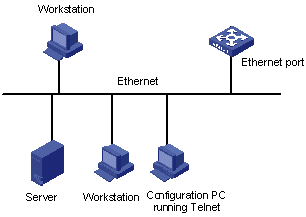
Figure 3-5 Network diagram for Telnet connection establishment
4) Launch Telnet on your PC, with the IP address of the management VLAN interface of the switch as the parameter, as shown in Figure 3-6.
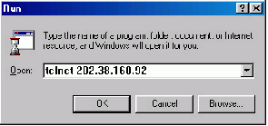
5) Enter the password when the Telnet window displays “Login authentication” and prompts for login password. The CLI prompt (such as <H3C>) appears if the password is correct. If all VTY user interfaces of the switch are in use, you will fail to establish the connection and receive the message that says “All user interfaces are used, please try later!”. A H3C series Ethernet switch can accommodate up to five Telnet connections at the same time.
6) After successfully Telneting to a switch, you can configure the switch or display the information about the switch by executing corresponding commands. You can also type ? at any time for help. Refer to the following chapters for the information about the commands.
& Note:
l A Telnet connection is terminated if you delete or modify the IP address of the VLAN interface in the Telnet session.
l By default, commands of level 0 are available to Telnet users authenticated by password. Refer to the Command Hierarchy/Command View section in Command Line Interface module for information about command hierarchy.
3.5.2 Telneting to Another Switch from the Current Switch
You can Telnet to another switch from the current switch. In this case, the current switch operates as the Telnet client, and the other operates as the Telnet server. If the interconnected Ethernet ports of the two switches are in the same LAN segment, make sure the IP addresses of the two management VLAN interfaces to which the two Ethernet ports belong to are of the same network segment, or the route between the two VLAN interfaces is available.
As shown in Figure 3-7, after Telneting to a switch (labeled as Telnet client), you can Telnet to another switch (labeled as Telnet server) by executing the telnet command and then to configure the later.

Figure 3-7 Network diagram for Telneting to another switch from the current switch
1) Perform Telnet-related configuration on the switch operating as the Telnet server. Refer to section Telnet Configuration with Authentication Mode Being None, section Telnet Configuration with Authentication Mode Being Password, and section Telnet Configuration with Authentication Mode Being Scheme for more.
2) Telnet to the switch operating as the Telnet client.
3) Execute the following command on the switch operating as the Telnet client:
<H3C> telnet xxxx
Where xxxx is the IP address or the host name of the switch operating as the Telnet server. You can use the ip host to assign a host name to a switch.
4) Enter the password. If the password is correct, the CLI prompt (such as <H3C>) appears. If all VTY user interfaces of the switch are in use, you will fail to establish the connection and receive the message that says “All user interfaces are used, please try later!”.
5) Step 5: After successfully Telneting to the switch, you can configure the switch or display the information about the switch by executing corresponding commands. You can also type ? at any time for help. Refer to the following chapters for the information about the commands.
Chapter 4 Logging in Using Modem
When logging into a switch using a Modem, go to these sections for information you are interested in:
l Configuration on the Administrator Side
l Configuration on the Switch Side
l Modem Connection Establishment
l Modem Attributes Configuration
4.1 Introduction
The administrator can log into the console port of a remote switch using a Modem through public switched telephone network (PSTN) if the remote switch is connected to the PSTN through a Modem. When a network operates improperly or is inaccessible, you can log into the switches in the network in this way to configure these switches, to query logs and trap messages, and to locate problems.
To log into a switch in this way, you need to configure the administrator side and the switch properly, as listed in the following table.
Table 4-1 Requirements for logging into a switch using a Modem
|
Item |
Requirement |
|
Administrator side |
The PC can communicate with the Modem connected to it. |
|
The Modem is properly connected to PSTN. |
|
|
The telephone number of the switch side is available. |
|
|
Switch side |
The Modem is connected to the console port of the switch properly. |
|
The Modem is properly configured. |
|
|
The Modem is properly connected to PSTN and a telephone set. |
|
|
The authentication mode and other related settings are configured on the switch. Refer to Table 2-3. |
4.2 Configuration on the Administrator Side
The PC can communicate with the Modem connected to it. The Modem is properly connected to PSTN. And the telephone number of the switch side is available.
4.3 Configuration on the Switch Side
4.3.1 Modem Configuration
Perform the following configuration on the Modem directly connected to the switch:
AT&F ----------------------- Restore the factory settings
ATS0=1 ----------------------- Configure to answer automatically after the first ring
AT&D ----------------------- Ignore DTR signal
AT&K0 ----------------------- Disable flow control
AT&R1 ----------------------- Ignore RTS signal
AT&S0 ----------------------- Set DSR to high level by force
ATEQ1&W ----------------------- Disable the modem from returning command response and the result, save the changes
You can verify your configuration by executing the AT&V command.
& Note:
l The above configuration is unnecessary to the Modem on the administrator side.
l The configuration commands and the output of different Modems may differ. Refer to the user manual of the Modem when performing the above configuration.
4.3.2 Switch Configuration
& Note:
After logging into a switch through its console port by using a Modem, you will enter the AUX user interface. The corresponding configuration on the switch is the same as those when logging into the switch locally through its console port except that:
l When you log in through the console port using a Modem, the baud rate of the console port is usually set to a value lower than the transmission speed of the Modem. Otherwise, packets may get lost.
l Other settings of the console port, such as the check mode, the stop bits, and the data bits, remain the default.
The configuration on the switch depends on the authentication mode the user is in. Refer to Table 2-3 for the information about authentication mode configuration.
I. Configuration on switch when the authentication mode is none
Refer to section Console Port Login Configuration with Authentication Mode Being None.
II. Configuration on switch when the authentication mode is password
Refer to section Console Port Login Configuration with Authentication Mode Being Password.
III. Configuration on switch when the authentication mode is scheme
Refer to section Console Port Login Configuration with Authentication Mode Being Scheme.
4.4 Modem Connection Establishment
1) Before using Modem to log in to the switch, perform corresponding configuration for different authentication modes on the switch. Refer to section Console Port Login Configuration with Authentication Mode Being None, section Console Port Login Configuration with Authentication Mode Being Password, and section Console Port Login Configuration with Authentication Mode Being Scheme for more information.
2) Perform the following configuration to the Modem directly connected to the switch.
AT&F ----------------------- Restore the factory settings
ATS0=1 ----------------------- Configure to answer automatically after the first ring
AT&D ----------------------- Ignore DTR signal
AT&K0 ----------------------- Disable flow control
AT&R1 ----------------------- Ignore RTS signal
AT&S0 ----------------------- Set DSR to high level by force
ATEQ1&W ----------------------- Disable the modem from returning command response and the result, save the changes
You can verify your configuration by executing the AT&V command.
& Note:
l The configuration commands and the output of different Modems may differ. Refer to the user manual of the Modem when performing the above configuration.
l It is recommended that the baud rate of the AUX port (also the console port) be set to a value lower than the transmission speed of the Modem. Otherwise, packets may get lost.
3) Connect your PC, the Modems, and the switch, as shown in the following figure.
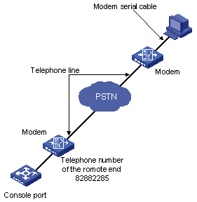
Figure 4-1 Establish the connection by using Modems
4) Launch a terminal emulation program on the PC and set the telephone number to call the Modem directly connected to the switch, as shown in Figure 4-2 and Figure 4-3. Note that you need to set the telephone number to that of the Modem directly connected to the switch.
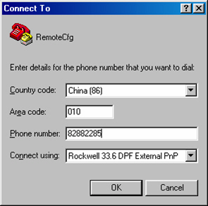
Figure 4-2 Set the telephone number
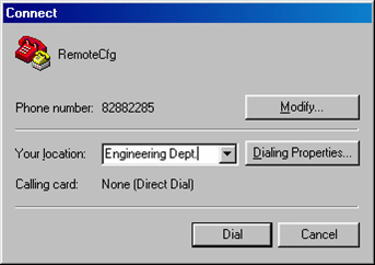
Figure 4-3 Call the Modem
5) Provide the password on the emulation grogram when prompted. If the password is correct, the prompt (such as <H3C>) appears. You can then configure or manage the switch. You can also enter the character ? at anytime for help. Refer to the following chapters for information about the configuration commands.
& Note:
If you perform no AUX user-related configuration on the switch, the commands of level 3 are available to Modem users. Refer to the CLI module for information about command level.
4.5 Modem Attributes Configuration
You can configure the Modem-related parameters.
4.5.1 Configuration Prerequisites
l You have configured the login mode for users on the switch.
l Network connection for Modem dial-up configuration has been established.
4.5.2 Configuration Procedure
Follow these steps to configure Modem attributes:
|
To do… |
Use the command… |
Remarks |
|
Enter system view |
system-view |
— |
|
Enter AUX user interface view |
user-interface aux 0 |
— |
|
Enable Modem call-in/call-in and call-out |
modem [ call-in | both ] |
Required Call-in and call-out are allowed when the command is executed without any keyword. |
|
Set the answer mode to auto answer. |
modem auto-answer |
Optional By default, manual answer mode is adopted. |
|
Configure the carrier detection timeout time after off-hook during call-in connection setup |
modem timer answer seconds |
Optional 30 seconds by default. |
4.5.3 Configuration Example
l Enable Modem call-in and call-out, set the answer mode to auto answer, and set the timeout time to 45 seconds.
Configuration procedure:
<H3C> system-view
System View: return to User View with Ctrl+Z.
[H3C] user-interface aux 0
[H3C-ui-aux0] modem both
[H3C-ui-aux0] modem auto-answer
[H3C-ui-aux0] modem timer answer 45
Chapter 5 Logging in through NMS
When logging into a switch through NMS, go to these sections for information you are interested in:
l Connection Establishment Using NMS
5.1 Introduction
You can also log into a switch through a network management station (NMS ), and then configure and manage the switch through the agent module on the switch.
l NMS: network management station.
l The agent here refers to the agent server software running on network devices (switches).
l The simple Network Management Protocol (SNMP) is applied between the NMS and the agent.
To log into a switch through an NMS, you need to perform related configuration on both the NMS and the switch.
Table 5-1 Requirements for logging into a switch through an NMS
|
Item |
Requirement |
|
Switch |
The management VLAN of the switch is configured. The route between the NMS and the management VLAN of the switch is available. (Refer to the Management VLAN Configuration module for more.) |
|
The basic SNMP functions are configured. (Refer to the SNMP module for more.) |
|
|
NMS |
The NMS is properly configured. (Refer to the user manual of your NMS for more.) |
5.2 Connection Establishment Using NMS
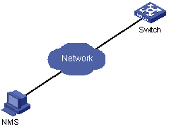
Figure 5-1 Network diagram for logging in through an NMS
Chapter 6 User Control
When configuring user control, go to these sections for information you are interested in:
l Controlling Network Management Users by Source IP Addresses
6.1 Introduction
A switch provides ways to control different types of login users, as listed in Table 6-1.
Table 6-1 Ways to control different types of login users
|
Login mode |
Control method |
Implementation |
Related section |
|
Telnet |
By source IP addresses |
Through basic ACL |
|
|
By source and destination IP addresses |
Through advanced ACL |
Section Controlling Telnet Users by Source and Destination IP Addresses. |
|
|
SNMP |
By source IP addresses |
Through basic ACL |
Section Controlling Network Management Users by Source IP Addresses. |
6.2 Controlling Telnet Users
The controlling policy against Telnet users is determined, including the source and destination IP addresses and source MAC addresses to be controlled and the controlling actions (permitting or denying).
6.2.1 Controlling Telnet Users by Source IP Addresses
Follow these steps to control Telnet users by source IP addresses:
|
To do… |
Use the command… |
Remarks |
|
Enter system view |
system-view |
— |
|
Create a basic ACL or enter basic ACL view |
acl { number acl-number | name acl-name [ advanced | basic | link | user ] } [ match-order { config | auto } ] |
As for the acl number command, the config keyword is specified by default. |
|
Define rules for the ACL |
rule [ rule-id ] { permit | deny } [ source { source-addr wildcard | any } | fragment | time-range time-name ]* |
Required |
|
Return to system view |
quit |
— |
|
Enter user interface view |
user-interface [ type ] first-number [ last-number ] |
— |
|
Apply the ACL to control Telnet users by source IP addresses |
acl acl-number { inbound | outbound } |
Required The inbound keyword specifies to filter the users trying to Telnet to the current switch. The outbound keyword specifies to filter users trying to Telnet to other switches from the current switch. |
6.2.2 Controlling Telnet Users by Source and Destination IP Addresses
Controlling Telnet users by source and destination IP addresses is achieved by applying advanced ACLs, which are numbered from 3000 to 3999. Refer to the ACL module for information about defining an ACL.
Follow these steps to control Telnet users by source and destination IP addresses:
|
To do… |
Use the command… |
Remarks |
|
Enter system view |
system-view |
— |
|
Create an advanced ACL or enter advanced ACL view |
acl { number acl-number | name acl-name [ advanced | basic | link | user ] } [ match-order { config | auto } ] |
As for the acl number command, the config keyword is specified by default. |
|
Define rules for the ACL |
rule [ rule-id ] { permit | deny } protocol [ source { source-addr wildcard | any } ] [ destination { dest-addr dest-mask | any } ] [ source-port operator port1 [ port2 ] ] [ destination-port operator port1 [ port2 ] ] [ icmp-type type code ] [ established ] [ [ precedence precedence | tos tos ]* | dscp dscp ] [ fragment ] [ time-range time-name ] |
Required You can define rules as needed to filter by specific source and destination IP addresses. |
|
Return to system view |
quit |
— |
|
Enter user interface view |
user-interface [ type ] first-number [ last-number ] |
— |
|
Apply the ACL to control Telnet users by specified source and destination IP addresses |
acl acl-number { inbound | outbound } |
Required The inbound keyword specifies to filter the users trying to Telnet to the current switch. The outbound keyword specifies to filter users trying to Telnet to other switches from the current switch. |
6.3 Controlling Network Management Users by Source IP Addresses
You can manage a H3C series Ethernet switch through network management software. Network management users can access switches through SNMP.
You need to perform the following two operations to control network management users by source IP addresses.
l Defining an ACL
l Applying the ACL to control users accessing the switch through SNMP
6.3.1 Prerequisites
The controlling policy against network management users is determined, including the source IP addresses to be controlled and the controlling actions (permitting or denying).
6.3.2 Controlling Network Management Users by Source IP Addresses
Controlling network management users by source IP addresses is achieved by applying basic ACLs, which are numbered from 2000 to 2999.
Follow these steps to control network management users by source IP addresses:
|
To do… |
Use the command… |
Remarks |
|
Enter system view |
system-view |
— |
|
Create a basic ACL or enter basic ACL view |
acl { number acl-number | name acl-name [ advanced | basic | link | user ] } [ match-order { config | auto } ] |
As for the acl number command, the config keyword is specified by default. |
|
Define rules for the ACL |
rule [ rule-id ] { permit | deny } [ source { source-addr wildcard | any } | fragment | time-range time-name ]* |
Required |
|
Return to system view |
quit |
— |
|
Apply the ACL while configuring the SNMP community name |
snmp-agent community { read | write } community-name [ mib-view view-name | acl acl-number ]* |
Optional By default, SNMPv1 and SNMPv2c use community name to access. |
|
Apply the ACL while configuring the SNMP group name |
snmp-agent group { v1 | v2c } group-name [ read-view read-view ] [ write-view write-view ] [ notify-view notify-view ] [ acl acl-number ] snmp-agent group v3 group-name [ authentication | privacy ] [ read-view read-view ] [ write-view write-view ] [ notify-view notify-view ] [ acl acl-number ] |
Optional By default, the authentication mode and the encryption mode are configured as none for the snmp-agent group v3 group-name command. |
|
Apply the ACL while configuring the SNMP user name |
snmp-agent usm-user { v1 | v2c } user-name group-name [ acl acl-number ] snmp-agent usm-user v3 user-name group-name [ authentication-mode { md5 | sha } auth-password privacy-mode des56 priv-password ] [ acl acl-number ] |
Optional |
& Note:
You can specify different ACLs while configuring the SNMP community name, the SNMP group name, and the SNMP user name.
As SNMP community name is a feature of SNMPv1 and SNMPv2c, the specified ACLs in the command that configures SNMP community names (the snmp-agent community command) take effect in the network management systems that adopt SNMPv1 or SNMPv2c.
Similarly, as SNMP group name and SNMP user name are features of SNMPv2c and the higher SNMP versions, the specified ACLs in the commands that configure SNMP group names and SNMP user names take effect in the network management systems that adopt SNMPv2c or higher SNMP versions. If you specify ACLs in the two commands, the network management users are filtered by both SNMP group name and SNMP user name.
6.3.3 Configuration Example
I. Network requirements
Only SNMP users sourced from the IP addresses of 10.110.100.52 and 10.110.100.46 are permitted to access the switch.
II. Network diagram
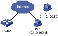
Figure 6-1 Network diagram for controlling SNMP users using ACLs
III. Configuration procedure
# Define a basic ACL.
<H3C> system-view
[H3C] acl number 2000 match-order config
[H3C-acl-basic-2000] rule 1 permit source 10.110.100.52 0
[H3C-acl-basic-2000] rule 2 permit source 10.110.100.46 0
[H3C-acl-basic-2000] rule 3 deny source any
[H3C-acl-basic-2000] quit
# Apply the ACL to only permit SNMP users sourced from the IP addresses of 10.110.100.52 and 10.110.100.46 to access the switch.
[H3C] snmp-agent community read aaa acl 2000
[H3C] snmp-agent group v2c groupa acl 2000
[H3C] snmp-agent usm-user v2c usera groupa acl 2000