- Table of Contents
-
- H3C S7500 Series Operation Manual(Release 3100 Series)-(V1.04)
- 00-1Cover
- 00-2Overview
- 01-CLI Configuration
- 02-Login Configuration
- 03-Configuration File Management Configuration
- 04-VLAN Configuration
- 05-Extended VLAN Application Configuration
- 06-IP Address-IP Performance-IPX Configuration
- 07-GVRP Configuration
- 08-QinQ Configuration
- 09-Port Basic Configuration
- 10-Link Aggregation Configuration
- 11-Port Isolation Configuration
- 12-Port Binding Configuration
- 13-DLDP Configuration
- 14-MAC Address Table Configuration
- 15-MSTP Configuration
- 16-Routing Protocol Configuration
- 17-Multicast Configuration
- 18-802.1x Configuration
- 19-AAA-RADIUS-HWTACACS-EAD Configuration
- 20-Traffic Accounting Configuration
- 21-VRRP-HA Configuration
- 22-ARP Configuration
- 23-DHCP Configuration
- 24-ACL Configuration
- 25-QoS Configuration
- 26-Mirroring Configuration
- 27-Cluster Configuration
- 28-PoE Configuration
- 29-UDP-Helper Configuration
- 30-SNMP-RMON Configuration
- 31-NTP Configuration
- 32-SSH Terminal Service Configuration
- 33-File System Management Configuration
- 34-FTP and TFTP Configuration
- 35-Information Center Configuration
- 36-DNS Configuration
- 37-System Maintenance and Debugging Configuration
- 38-HWPing Configuration
- 39-RRPP Configuration
- 40-NAT-Netstream-Policy Routing Configuration
- 41-Telnet Protection Configuration
- 42-Hardware-Dependent Software Configuration
- Related Documents
-
| Title | Size | Download |
|---|---|---|
| 31-NTP Configuration | 201 KB |
1.1.2 Working Principle of NTP
1.2 NTP Implementation Mode Configuration
1.2.2 Configuring NTP Implementation Modes
1.3 Access Control Permission Configuration
1.4 NTP Authentication Configuration
1.4.2 Configuring NTP Authentication
1.5 Configuration of Optional NTP Parameters
1.6 Displaying and Maintaining NTP
1.7.1 NTP Server Mode Configuration
1.7.2 NTP Peer Mode Configuration
1.7.3 NTP Broadcast Mode Configuration
1.7.4 NTP Multicast Mode Configuration
1.7.5 NTP Server Mode with Authentication Configuration
Chapter 1 NTP Configuration
1.1 Introduction to NTP
Network time protocol (NTP) is a time synchronization protocol defined by RFC1305. It is used for time synchronization among a set of distributed time servers and clients. NTP transmits packets through UDP port 123.
NTP is intended for time synchronization of all devices that have clocks in a network, so that the clocks of all devices can keep consistent. This enables the applications that require unified time.
A system running NTP not only can be synchronized by other clock sources, but also can serve as a clock source to synchronize other clocks. Besides, it can synchronize, or be synchronized by other systems by exchanging NTP packets.
1.1.1 Applications of NTP
NTP is mainly applied to synchronizing the clocks of all the network devices in a network. For example:
l In network management, the analysis of the log information and debugging information collected from different devices is meaningful and valid only when network devices that generate the information adopt the same time.
l The accounting system requires that the clocks of all the network devices be consistent.
l Some functions, such as restarting all the network devices in a network simultaneously, require that they adopt the same time.
l When multiple systems cooperate to handle a rather complex event, to ensure a correct execution order, they must adopt the same time.
l To perform incremental backup operations between a backup server and a host, you must make sure they adopt the same time.
As setting the system time manually in a network with many devices leads to a lot of workload and cannot ensure the accuracy, it is unfeasible for an administrator to perform the operation. However, an administrator can synchronize the devices in a network with required accuracy by performing NTP configuration.
NTP benefits from the following advantages:
l Defining the accuracy of clocks by strata to synchronize the time of all the devices in a network quickly
l Supporting access control and MD5 authentication
l Sending protocol packets in unicast, multicast or broadcast mode
& Note:
The accuracy of a clock is determined by its stratum, which ranges from 1 to 16. The stratum of the reference clock ranges from 1 to 15. The accuracy descends with the increasing of stratum number. The clocks with the stratum of 16 are in unsynchronized state and cannot serve as reference clocks.
1.1.2 Working Principle of NTP
The working principle of NTP is shown in Figure 1-1.
In Figure 1-1, The Ethernet switch A (LS_A) is connected to the Ethernet switch B (LS_B) through their Ethernet ports. Both of them have system clocks of their own, and they need to synchronize the clocks of each other through NTP. For ease of understanding, suppose that:
l Before the system clocks of LS_A and LS_B are synchronized, the clock of LS_A is set to 10:00:00am, and the clock of LS_B is set to 11:00:00am.
l LS_B serves as the NTP time server, that is, the clock of LS_A will be synchronized to that of LS_B.
l It takes one second for a packet sent by one switch to reach the other.
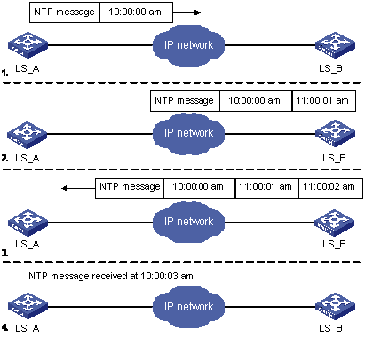
Figure 1-1 Working principle of NTP
The procedures of synchronizing system clocks are as follows:
l LS_A sends an NTP packet to LS_B, with the timestamp identifying the time when it is sent (that is, 10:00:00am, noted as T1) carried.
l When the packet arrives at LS_B, LS_B inserts its own timestamp, which identifies 11:00:01am (noted as T2) into the packet.
l Before this NTP packet leaves LS_B, LS_B inserts its own timestamp once again, which identifies 11:00:02am (noted as T3).
l When receiving the response packet, the local time of LS_A is 10:00:03am.
At this time, LS_A has enough information to calculate the following two parameters:
l The delay for an NTP packet to make a round trip between LS_A and LS_B: delay = (T4 -T1)-(T3 -T2).
l The time offset of LS_A with regard to LS_B: offset = ((T2 -T1) + (T3 -T4))/2.
LS_A can then set its own clock according to the above information to synchronize its clock to that of LS_B.
For the detailed information, refer to RFC1305.
1.1.3 NTP Implementation Mode
To accommodate networks of different structures and switches in different network positions, NTP can operate in multiple modes, as described in the following.
I. Client/Server mode
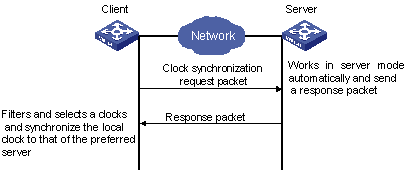
Figure 1-2 NTP implementation mode: client/Sever mode
II. Peer mode
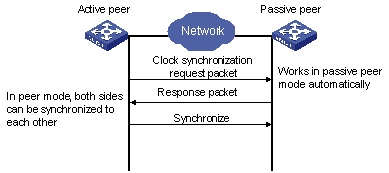
Figure 1-3 NTP implementation mode: peer mode
In peer mode, the active peer sends clock synchronization packets first, and its peer works as a passive peer automatically.
If both of the peers have reference clocks, the one with smaller stratum is adopted.
III. Broadcast mode
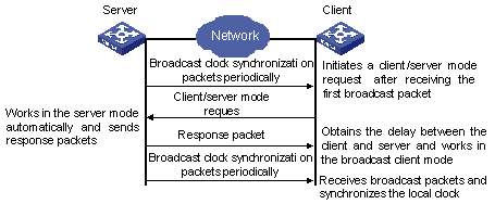
Figure 1-4 NTP implementation mode: broadcast mode
IV. Multicast mode
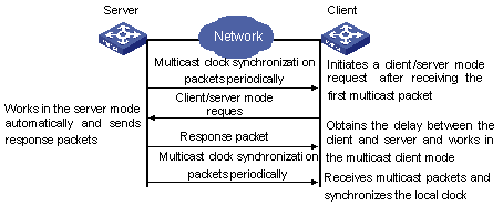
Figure 1-5 NTP implementation mode: multicast mode
Table 1-1 describes how the above mentioned NTP modes are implemented on an S7500 series switch.
Table 1-1 NTP implementation modes on an S7500 series switch
|
NTP implementation mode |
Configuration on S7500 switches |
|
Client/Server mode |
Configure the S7500 switch to operate in the NTP server mode. In this case, the remote server operates as the local time server, and the S7500 switch operates as the client. |
|
Peer mode |
Configure the S7500 switch to operate in NTP peer mode. In this case, the remote server operates as the peer of the S7500 switch, and the S7500 switch operates as the active peer. |
|
Broadcast mode |
l Configure the S7500 switch to operate in NTP broadcast server mode. In this case, the S7500 switch broadcasts NTP packets through the VLAN interface configured on the switch. l Configure the S7500 switch to operate in NTP broadcast client mode. In this case, the S7500 switch receives broadcast NTP packets through the VLAN interface configured on the switch. |
|
Multicast mode |
l Configure the S7500 switch to operate in NTP multicast server mode. In this case, the S7500 switch sends multicast NTP packets through the VLAN interface configured on the switch. l Configure the S7500 switch to operate in NTP multicast client mode. In this case, the S7500 switch receives multicast NTP packets through the VLAN interface configured on the switch. |
1.2 NTP Implementation Mode Configuration
A switch can operate in the following NTP modes:
l NTP client mode
l NTP server mode
l NTP peer mode
l NTP broadcast server mode
l NTP broadcast client mode
l NTP multicast server mode
l NTP multicast client mode
1.2.1 Prerequisites
When an S7500 switch operates in NTP server mode or NTP peer mode, you need to perform configuration on the client or the active peer only. When an S7500 switch operates in NTP broadcast mode or NTP multicast mode, you need to perform configurations on both the server side and the client side.
1.2.2 Configuring NTP Implementation Modes
Follow these steps to configure NTP implementation modes:
|
To do... |
Use the command... |
Remarks |
|
Enter system view |
system-view |
— |
|
Configure to operate in the NTP client mode |
ntp-service unicast-server { remote-ip | server-name } [ authentication-keyid key-id | priority | source-interface interface -type interface-number | version number ]* |
Optional By default, no Ethernet switch operates in the NTP client mode |
|
Configure to operate in the NTP peer mode |
ntp-service unicast-peer { remote-ip | peer-name } [ authentication-keyid key-id | priority | source-interface interface -type interface-number | version number ]* |
Optional By default, no Ethernet switch operates in the NTP peer mode |
|
Enter interface view |
interface interface -type interface-number |
— |
|
Configure to operate in the NTP broadcast client mode |
ntp-service broadcast-client |
Optional By default, no Ethernet switch operates in the NTP broadcast client mode |
|
Configure to operate in the NTP broadcast server mode |
ntp-service broadcast-server [ authentication-keyid key-id | version number ]* |
Optional By default, no Ethernet switch operates in the NTP broadcast server mode |
|
Configure to operate in the NTP multicast client mode |
ntp-service multicast-client [ ip-address ] |
Optional By default, no Ethernet switch operates in the NTP multicast client mode |
|
Configure to operate in the NTP multicast server mode |
ntp-service multicast-server [ ip-address ] [ authentication-keyid keyid | ttl ttl-number | version number ]* |
Optional By default, no Ethernet switch operates in the NTP multicast server mode |
I. NTP client mode
When an S7500 series switch operates in the NTP client mode,
l The remote server identified by the remote-ip argument operates as the NTP time server. The S7500 series switch operates as the client, whose clock is synchronized to the NTP server. (In this case, the clock of the NTP server is not synchronized to the local client.)
l When the remote-ip argument is an IP address of a host, it cannot be a broadcast or a multicast address, neither can it be the IP address of a reference clock.
II. NTP peer mode
When an S7500 series switch operates in NTP peer mode,
l The remote server identified by the remote-ip argument operates as the peer of the S7500 series switch, and the S7500 series switch operates as the active peer. The clock of the S7500 series switch can be synchronized to the remote server or be used to synchronize the clock of the remote server.
l When the remote-ip argument is an IP address of a host, it cannot be a broadcast or a multicast address, neither can it be the IP address of a reference clock.
III. NTP broadcast server mode
When an S7500 series switch operates in NTP broadcast server mode, it broadcasts a clock synchronization packet periodically. The devices which are configured to be in the NTP broadcast client mode will respond this packet and start the clock synchronization procedure.
IV. NTP multicast server mode
When an S7500 series switch operates in NTP multicast server mode, it multicasts a clock synchronization packet periodically. The devices which are configured to be in the NTP multicast client mode will respond this packet and start the clock synchronization procedure. In this mode, the switch can accommodate up to 1,024 multicast clients.
& Note:
l The total number of the servers and peers configured for a switch can be up to 128.
l After the configuration, the S7500 series switch does not establish connections with the peer if it operates in NTP server mode. Whereas if it operates in any of the other modes, it establishes connections with the peer.
l If an S7500 series switch operates as a passive peer in peer mode, NTP broadcast client mode, or NTP multicast client mode, the connections it establishes with the peers are dynamic. If it operates in other modes, the connections it establishes with the peers are static.
1.3 Access Control Permission Configuration
Access control permission to NTP server is a security measure that is of the minimum extent. Authentication is more reliable comparing to it.
An access request made to an NTP server is matched from the highest permission to the lowest, that is, in the order of peer, server, synchronization, and query.
Follow these steps to configure the access control permission to the local NTP server:
|
To do... |
Use the command... |
Remarks |
|
Enter system view |
system-view |
— |
|
Configure the access control permission to the local NTP server |
ntp-service access { peer | server | synchronization | query } acl-number |
Optional By default, the access control permission to the local NTP server is peer |
1.4 NTP Authentication Configuration
For the networks with higher security requirements, you can specify to perform authentications when enabling NTP. With the authentications performed on both the client side and the server side, the client is synchronized only to the server that passes the authentication. This improves network security.
1.4.1 Prerequisites
NTP authentication configuration involves:
l Configuring NTP authentication on the client
l Configuring NTP authentication on the server
Note the following when performing NTP authentication configuration:
l If the NTP authentication is not enabled on a client, the client can be synchronized to a server regardless of the NTP authentication configuration performed on the server (assuming that the related configurations are performed).
l You need to couple the NTP authentication with a trusted key.
l The configurations performed on the server and the client must be the same.
l A client with NTP authentication enabled is only synchronized to a server that can provide a trusted key.
1.4.2 Configuring NTP Authentication
I. Configuring NTP authentication on the client
Follow these steps to configure NTP authentication on the client:
|
To do... |
Use the command... |
Remarks |
|
Enter system view |
system-view |
— |
|
Enable NTP authentication globally |
ntp-service authentication enable |
Required By default, the NTP authentication is disabled |
|
Configure the NTP authentication key |
ntp-service authentication-keyid key-id authentication-mode md5 value |
Required By default, the NTP authentication key is not configured |
|
Configure the specified key to be a trusted key |
ntp-service reliable authentication-keyid key-id |
Required By default, no trusted authentication key is configured |
|
Associate the specified key with the corresponding NTP server |
NTP client mode: ntp-service unicast-server { remote-ip | server-name } authentication-keyid key-id |
l In NTP client mode and NTP peer mode, you need to associate the specified key with the corresponding NTP server on the client. l You can associate the NTP server with the authentication key while configuring the switch to operate in a specific NTP mode. You can also associate them using this command after configuring the NTP mode where the switch is to operate |
|
Peer mode: ntp-service unicast-peer { remote-ip | peer-name } authentication-keyid key-id |
& Note:
l NTP authentication requires that the authentication keys configured for the server and the client are the same. Besides, the authentication keys must be trusted keys. Otherwise, the client cannot be synchronized with the server.
l In NTP server mode and NTP peer mode, you need to associate the specified key with the corresponding NTP server/active peer on the client/passive peer. In these two modes, multiple servers/active peers may be configured for a client/passive peer, and a client/passive peer chooses the server/active peer to synchronize to by the authentication key.
II. Configuring NTP authentication on the server
Follow these steps to configure NTP authentication on the server:
|
To do... |
Use the command... |
Remarks |
|
Enter system view |
system-view |
— |
|
Enable NTP authentication |
ntp-service authentication enable |
Required By default, NTP authentication is disabled |
|
Configure NTP authentication key |
ntp-service authentication-keyid key-id authentication-mode md5 value |
Required By default, NTP authentication key is not configured |
|
Configure the specified key to be a trusted key |
ntp-service reliable authentication-keyid key-id |
Required By default, an authentication key is not a trusted key |
|
Enter VLAN interface view |
interface interface-type interface-number |
— |
|
Associate a specified key with the corresponding NTP server |
Broadcast server mode: ntp-service broadcast-server authentication-keyid key-id |
l In NTP broadcast server mode and NTP multicast server mode, you need to associate the specified key with the corresponding NTP server on the server l You can associate an NTP server with an authentication key while configuring a switch to operate in a specific NTP mode. You can also associate them using this command after configuring the NTP mode where a switch is to operate |
|
Multicast server mode: ntp-service multicast-server authentication-keyid key-id |
& Note:
The procedures for configuring NTP authentication on the server are the same as those on the client. Besides, the client and the server must be configured with the same authentication key.
1.5 Configuration of Optional NTP Parameters
The configurations of optional NTP parameters are:
l Setting the local clock as the NTP master clock
l Configuring the local VLAN interface that sends NTP packets
l Configuring the number of the dynamic sessions that can be established locally
l Disabling the VLAN interface configured on a switch from receiving NTP packets
l Disabling NTP service globally
Follow these steps to configure optional NTP parameters:
|
To do... |
Use the command... |
Remarks |
|
Enter system view |
system-view |
— |
|
Configure the local clock as the NTP master clock |
ntp-service refclock-master [ ip-address ] [ stratum ] |
Optional |
|
Configure the local interface that sends NTP packets |
ntp-service source-interface interface-type interface-number |
Optional |
|
Configure the number of the sessions that can be established locally |
ntp-service max-dynamic-sessions number |
Optional By default, up to 100 dynamic sessions can be established locally. |
|
Enter VLAN interface view |
interface interface-type interface-number |
— |
|
Disable the interface from receiving NTP packets |
ntp-service in-interface disable |
Optional By default, a VLAN interface receives NTP packets. |
|
Return to system view |
quit |
— |
|
Disable NTP service globally |
ntp-service disable |
Optional By default, the NTP service is enabled |
![]() Caution:
Caution:
l The source IP address in an NTP packet is the address of the sending interface specified by the ntp-service unicast-server command or the ntp-service unicast-peer command if you provide the address of the sending interface in these two commands.
l Dynamic connections can only be established when a switch operates in passive peer mode, NTP broadcast client mode, or NTP multicast client mode. In other modes, the connections established are static.
1.6 Displaying and Maintaining NTP
|
To do... |
Use the command... |
Remarks |
|
Display the status of NTP service |
display ntp-service status |
Available in any view |
|
Display the information about the sessions maintained by NTP |
display ntp-service sessions [ verbose ] |
|
|
Display the brief information about the NTP time servers of the reference clock sources that the local device traces to |
display ntp-service trace |
1.7 Configuration Example
1.7.1 NTP Server Mode Configuration
I. Network requirements
Configure the local clock of S7500-1 to be the NTP master clock, with the stratum being 2.
S7500-2 operates in client mode, with S7500-1 as the time server. S7500-1 operates in server mode automatically.
II. Network diagram
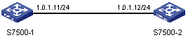
Figure 1-6 Network diagram for the NTP server mode configuration
III. Configuration procedures
Configure S7500-1.
# Set the local clock as the NTP master clock, with the stratum being 2.
<S7500-1> system-view
System View: return to User View with Ctrl+Z.
[S7500-1] ntp-service refclock-master 127.127.1.1 2
The following configurations are for S7500-2.
# View the NTP status of S7500-2 before synchronization.
<S7500-2> display ntp-service status
Service status: enabled
Clock status: unsynchronized
Clock stratum: 16
Reference clock ID: none
Nominal frequence: 99.8562 Hz
Actual frequence: 99.8562 Hz
Clock precision: 2^7
Clock offset: 0.0000 ms
Root delay: 0.00 ms
Root dispersion: 0.00 ms
Peer dispersion: 0.00 ms
Reference time: 00:00:00.000 UTC Jan 1 1900 (00000000.00000000)
# Configure S7500-1 to be the time server of S7500-2.
<S7500-2> system-view
[S7500-2] ntp-service unicast-server 1.0.1.11
# After the above configuration, S7500-2 is synchronized to S7500-1. View the NTP status of S7500-2.
[S7500-2] display ntp-service status
Service status: enabled
Clock status: synchronized
Clock stratum: 3
Reference clock ID: 1.0.1.11
Nominal frequence: 250.0000 Hz
Actual frequence: 249.9992 Hz
Clock precision: 2^19
Clock offset: 0.66 ms
Root delay: 27.47 ms
Root dispersion: 208.39 ms
Peer dispersion: 9.63 ms
Reference time: 17:03:32.022 UTC Thu Sep 6 2001 (BF422AE4.05AEA86C)
The above output information indicates that S7500-2 is synchronized to S7500-1, and the stratum of its clock is 3, one stratum higher than S7500-1.
# View the information about the NTP sessions of S7500-2. You can see that S7500-2 establishes a connection with S7500-1.
[S7500-2]dis ntp-service sessions
source reference stra reach poll now offset delay disper
**************************************************************************
[12345]1.0.1.11 127.127.1.1 2 1 64 1 350.1 15.1 0.0
note: 1 source(master),2 source(peer),3 selected,4 candidate,5 configured
1.7.2 NTP Peer Mode Configuration
I. Network requirements
H3C2 sets the local clock to be the NTP master clock, with the clock stratum being 2.
Configure an S7500 series switch to operate as a client, with H3C2 as the time server. H3C2 will then operate in the server mode automatically. Meanwhile, H3C3 sets the S7500 series switch to be its peer.
& Note:
This example assumes that:
l H3C2 is a switch that allows its local clock to be the master clock.
l H3C3 is a switch that allows its local clock to be the master clock and the stratum of its clock is 1.
II. Network diagram
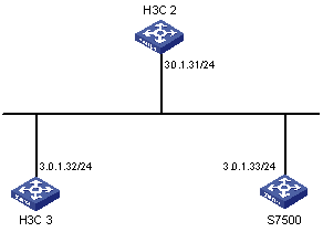
Figure 1-7 Network diagram for NTP peer mode configuration
III. Configuration procedures
1) Configure the S7500 series switch.
# Set H3C2 to be the time server.
<S7500> system-view
[S7500] ntp-service unicast-server 3.0.1.31
2) Configure H3C3 (after the S7500 series switch is synchronized to H3C2).
# Enter system view.
<H3C3> system-view
[H3C3]
# After the local synchronization, set the S7500 series switch to be its peer.
[H3C3] ntp-service unicast-peer 3.0.1.33
The S7500 series switch and H3C3 are configured to be peers with regard to each other. H3C3 operates in the active peer mode, while the S7500 series switch operates in the passive peer mode. Because the stratum of the local clock of H3C3 is 1, and that of the S7500 switch is 3, the S7500 series switch is synchronized to H3C3.
View the status of the S7500 switch after the synchronization.
[S7500] display ntp-service status
Service status: enabled
Clock status: synchronized
Clock stratum: 2
Reference clock ID: 3.0.1.32
Nominal frequency: 250.0000 Hz
Actual frequency: 249.9992 Hz
Clock precision: 2^19
Clock offset: 0.66 ms
Root delay: 27.47 ms
Root dispersion: 208.39 ms
Peer dispersion: 9.63 ms
Reference time: 17:03:32.022 UTC Thu Sep 6 2001 (BF422AE4.05AEA86C)
The output information indicates that the S7500 series switch is synchronized to H3C3 and the stratum of its local clock is 2, one stratum higher than H3C3.
# View the information about the NTP sessions of the S7500 series switch and you can see that a connection is established between the S7500 series switch and H3C3.
[S7500] display ntp-service sessions
source reference stra reach poll now offset delay disper
**************************************************************************
[2]3.0.1.32 127.127.1.0 1 1 64 1 350.1 15.1 0.0
note: 1 source(master),2 source(peer),3 selected,4 candidate,5 configured
1.7.3 NTP Broadcast Mode Configuration
I. Network requirements
H3C3 sets its local clock to be an NTP master clock, with the stratum being 2. NTP packets are broadcast through VLAN interface 2.
Configure S7500-1 and S7500-2 to listen to broadcast packets through their VLAN interface 2.
& Note:
This example assumes that H3C3 is a switch that supports the local clock being the master clock.
II. Network diagram
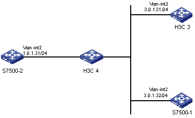
Figure 1-8 Network diagram for the NTP broadcast mode configuration
III. Configuration procedures
1) Configure H3C3.
# Enter system view.
<H3C3> system-view
[H3C3]
# Enter VLAN-interface 2 view.
[H3C3] interface Vlan-interface 2
[H3C3-Vlan-Interface2]
# Configure H3C3 to be the broadcast server and send broadcast packets through VLAN-interface 2.
[H3C3-Vlan-Interface2] ntp-service broadcast-server
2) Configure S7500-1.
# Enter system view.
<S7500-1> system-view
[S7500-1]
# Enter VLAN-interface 2 view.
[S7500-1] interface Vlan-interface 2
[S7500-1-Vlan-Interface2]
# Configure S7500-1 to be a broadcast client.
[S7500-1-Vlan-Interface2] ntp-service broadcast-client
3) Configure S7500-2
# Enter system view.
<S7500-2> system-view
[S7500-2]
# Enter VLAN-interface 2 view.
[S7500-2] interface Vlan-interface 2
[S7500-2-Vlan-Interface2]
# Configure S7500-2 to be a broadcast client.
[S7500-2-Vlan-Interface2] ntp-service broadcast-client
The above configuration configures S7500-1 and S7500-2 to listen to broadcast packets through their VLAN interface 2, and H3C3 to send broadcast packets through VLAN interface 2. Because S7500-2 does not reside in the same network segment with H3C3, S7500-2 cannot receive broadcast packets sent by H3C3, while S7500-1 is synchronized to H3C3 after receiving broadcast packets sent by H3C3.
View the status of S7500-1 after the synchronization.
[S7500-1] display ntp-service status
Service status: enabled
Clock status: synchronized
Clock stratum: 3
Reference clock ID: 3.0.1.31
Nominal frequency: 250.0000 Hz
Actual frequency: 249.9992 Hz
Clock precision: 2^19
Clock offset: 198.7425 ms
Root delay: 27.47 ms
Root dispersion: 208.39 ms
Peer dispersion: 9.63 ms
Reference time: 17:03:32.022 UTC Thu Sep 6 2001 (BF422AE4.05AEA86C)
The output information indicates that S7500-1 is synchronized to H3C3, with the clock stratum of 3, one stratum higher than H3C3.
# View the information about the NTP sessions of S7500-1 and you can see that a connection is established between S7500-1 and H3C3.
[S7500-1] display ntp-service sessions
source reference stra reach poll now offset delay disper
**************************************************************************
[1]3.0.1.31 127.127.1.0 2 1 64 377 26.1 199.53 9.7
note: 1 source(master),2 source(peer),3 selected,4 candidate,5 configured
1.7.4 NTP Multicast Mode Configuration
I. Network requirements
H3C3 sets the local clock to be NTP master clock, with the clock stratum of 2. It advertises multicast packets through VLAN interface 2.
Configure S7500-1 and S7500-2 to listen to multicast packets through their VLAN interface 2.
& Note:
This example assumes that H3C3 is a switch that supports the local clock being the master clock.
II. Network diagram
Figure 1-9 Network diagram for NTP multicast mode configuration
III. Configuration procedures
1) Configure H3C3.
# Enter system view.
<H3C3> system-view
[H3C3]
# Enter VLAN-interface 2 view.
[H3C3] interface Vlan-interface 2
# Configure H3C3 to be a multicast server.
[H3C3-Vlan-Interface2] ntp-service multicast-server
2) Configure S7500-1.
# Enter system view.
<S7500-1> system-view
[S7500-1]
# Enter VLAN-interface 2 view.
[S7500-1] interface vlan-interface 2
# Configure S7500-1 to be a multicast client.
[S7500-1-Vlan-interface2] ntp-service multicast-client
3) Configure S7500-2.
# Enter system view.
<S7500-2> system-view
[S7500-2]
# Enter VLAN-interface 2 view.
[S7500-2] interface Vlan-interface 2
# Configure S7500-2 to be a multicast client.
[S7500-2-Vlan-Interface2] ntp-service multicast-client
The above configuration configures S7500-1 and S7500-2 to listen to multicast packets through their VLAN interface 2, and H3C3 to advertise multicast packets through VLAN interface 2. Because S7500-2 does not reside in the same network segment with H3C3, S7500-2 cannot receive multicast packets sent by H3C3, while S7500-1 is synchronized to H3C3 after receiving multicast packets sent by H3C3.
View the status of S7500-1 after the synchronization.
[S7500-1] display ntp-service status
Service status: enabled
Clock status: synchronized
Clock stratum: 3
Reference clock ID: 3.0.1.31
Nominal frequency: 250.0000 Hz
Actual frequency: 249.9992 Hz
Clock precision: 2^19
Clock offset: 198.7425 ms
Root delay: 27.47 ms
Root dispersion: 208.39 ms
Peer dispersion: 9.63 ms
Reference time: 17:03:32.022 UTC Thu Sep 6 2001 (BF422AE4.05AEA86C)
The output information indicates that S7500-1 is synchronized to H3C3, with the clock stratum being 3, one stratum higher than H3C3.
# View the information about the NTP sessions of S7500-1 and you can see that a connection is established between S7500-1 and H3C3.
[S7500-1] display ntp-service sessions
source reference stra reach poll now offset delay disper
**************************************************************************
[1]3.0.1.31 127.127.1.0 2 1 64 377 26.1 199.53 9.7
note: 1 source(master),2 source(peer),3 selected,4 candidate,5 configured
1.7.5 NTP Server Mode with Authentication Configuration
I. Network requirements
The local clock of S7500-1 operates as the master NTP clock, with the clock stratum being 2.
S7500-2 operates in client mode with S7500-1 as the time server. S7500-1 operates in the server mode automatically. Meanwhile, NTP authentication is enabled on both sides.
II. Network diagram
Figure 1-10 Network diagram for NTP server mode with authentication configuration
III. Configuration procedures
1) Configure S7500-2.
# Enter system view.
<S7500-2> system-view
[S7500-2]
# Configure S7500-1 to be the time server.
[S7500-2] ntp-service unicast-server 1.0.1.11
# Enable NTP authentication.
[S7500-2] ntp-service authentication enable
# Set the MD5 key to 42, with the content being aNiceKey.
[S7500-2] ntp-service authentication-keyid 42 authentication-mode md5 aNiceKey
# Specify the key to be a trusted key.
[S7500-2] ntp-service reliable authentication-keyid 42
[S7500-2] ntp-service unicast-server 1.0.1.11 authentication-keyid 42
The above configuration synchronizes S7500-2 to S7500-1. As NTP authentication is not enabled on S7500-1, S7500-2 will fail to be synchronized to S7500-1.
The following configuration is needed for S7500-1.
# Enable authentication on S7500-1.
[S7500-1] system-view
[S7500-1] ntp-service authentication enable
# Set the MD5 key to 42, with the content being aNiceKey.
[S7500-1] ntp-service authentication-keyid 42 authentication-mode md5 aNiceKey
# Specify the key to be a trusted key.
[S7500-1] ntp-service reliable authentication-keyid 42
After the above configuration, S7500-2 can be synchronized to S7500-1. You can view the status of S7500-2 after the synchronization.
[S7500-2] display ntp-service status
Service status: enabled
Clock status: synchronized
Clock stratum: 3
Reference clock ID: 1.0.1.11
Nominal frequence: 250.0000 Hz
Actual frequence: 249.9992 Hz
Clock precision: 2^19
Clock offset: 0.66 ms
Root delay: 27.47 ms
Root dispersion: 208.39 ms
Peer dispersion: 9.63 ms
Reference time: 17:03:32.022 UTC Thu Sep 6 2001 (BF422AE4.05AEA86C)
The output information indicates that S7500-2 is synchronized to S7500-1, with the clock stratum being 3, one stratum higher than S7500-1.
# View the information about the NTP sessions of S7500-2 and you can see that a connection is established between S7500-2 and S7500-1.
<S7500-2> display ntp-service sessions
source reference stra reach poll now offset delay disper
**************************************************************************
[5]1.0.1.11 127.127.1.0 2 1 64 1 350.1 15.1 0.0
note: 1 source(master),2 source(peer),3 selected,4 candidate,5 configured