- Table of Contents
-
- H3C S7500 Series Operation Manual(Release 3100 Series)-(V1.04)
- 00-1Cover
- 00-2Overview
- 01-CLI Configuration
- 02-Login Configuration
- 03-Configuration File Management Configuration
- 04-VLAN Configuration
- 05-Extended VLAN Application Configuration
- 06-IP Address-IP Performance-IPX Configuration
- 07-GVRP Configuration
- 08-QinQ Configuration
- 09-Port Basic Configuration
- 10-Link Aggregation Configuration
- 11-Port Isolation Configuration
- 12-Port Binding Configuration
- 13-DLDP Configuration
- 14-MAC Address Table Configuration
- 15-MSTP Configuration
- 16-Routing Protocol Configuration
- 17-Multicast Configuration
- 18-802.1x Configuration
- 19-AAA-RADIUS-HWTACACS-EAD Configuration
- 20-Traffic Accounting Configuration
- 21-VRRP-HA Configuration
- 22-ARP Configuration
- 23-DHCP Configuration
- 24-ACL Configuration
- 25-QoS Configuration
- 26-Mirroring Configuration
- 27-Cluster Configuration
- 28-PoE Configuration
- 29-UDP-Helper Configuration
- 30-SNMP-RMON Configuration
- 31-NTP Configuration
- 32-SSH Terminal Service Configuration
- 33-File System Management Configuration
- 34-FTP and TFTP Configuration
- 35-Information Center Configuration
- 36-DNS Configuration
- 37-System Maintenance and Debugging Configuration
- 38-HWPing Configuration
- 39-RRPP Configuration
- 40-NAT-Netstream-Policy Routing Configuration
- 41-Telnet Protection Configuration
- 42-Hardware-Dependent Software Configuration
- Related Documents
-
| Title | Size | Download |
|---|---|---|
| 37-System Maintenance and Debugging Configuration | 527 KB |
Chapter 1 Boot ROM and Host Software Loading
1.1 Introduction to Loading Approaches
1.2.2 Loading Software Using XMODEM through Console Port
1.2.3 Loading Software Using TFTP through Ethernet Port
1.2.4 Loading Software Using FTP through Ethernet Port
1.3.1 Remote Loading Using FTP
1.3.2 Remote Loading Using TFTP
Chapter 2 Basic System Configuration and Debugging
2.1 Basic System Configuration
2.1.1 Basic System Configuration Task List
2.1.2 Entering System View from User View
2.1.3 Setting the System Name of the Switch
2.1.4 Setting the Date and Time of the System
2.1.5 Setting the Local Time Zone
2.1.6 Setting the Daylight Saving Time.
2.1.7 Setting the CLI Language Mode
2.1.8 Returning from Current View to Lower Level View
2.1.9 Returning from Current View to User View
2.2 Displaying the System Status
2.3.1 Enabling/Disabling System Debugging
2.3.2 Displaying Debugging Status
2.3.3 Displaying Operating Information about Modules in System
Chapter 3 Network Connectivity Test
4.1 Introduction to Device Management
4.2 Device Management Configuration
4.2.1 Device Management Configuration Task List
4.2.2 Restarting the Ethernet Switch
4.2.3 Rebooting a Card of Ethernet Switch
4.2.4 Scheduling a Reboot on the Switch.
4.2.5 Specifying the APP to be Adopted at Reboot
4.2.7 Upgrading Boot ROM along with the Upgrade of ARP
4.2.8 Setting Card Temperature Threshold
4.2.9 Enabling/Disabling RDRAM
4.2.10 Enabling System Load Sharing.
4.3 Configuring Pause Frame Protection Mechanism
4.3.1 Pause Frame Protection Mechanism Configuration Task
4.3.2 Pause Frame Protection Mechanism Configuration Example
4.4 Configuring Layer 3 Connectivity Detection
4.4.1 Introduction to layer 3 connectivity detection
4.4.2 Layer 3 Connectivity Detection Configuration Task
4.4.3 Layer 3 Connectivity Detection Configuration Example
4.5 Configuring Queue Traffic Monitoring
4.5.1 Queue Traffic Monitoring Configuration Task
4.5.2 Queue Traffic Monitoring Configuration Example
4.6 Configuring Error Packets Monitoring
4.6.1 Error Packets Monitoring Configuration Task
4.6.2 Error Packets Monitoring Configuration Example
4.7 Displaying the Device Management Configuration
4.8 Remote Switch Update Configuration Example
Chapter 1 Boot ROM and Host Software Loading
Traditionally, the loading of switch software is accomplished through a serial port. This approach is slow, inconvenient, and cannot be used for remote loading. To resolve these problems, the TFTP and FTP modules are introduced into the switch. With these modules, you can load/download software/files conveniently to the switch through an Ethernet port.
This chapter introduces how to load Boot ROM and host software to a switch locally and how to do this remotely.
When configuring Boot ROM and host software loading, go to these sections for information you are interested in:
l Introduction to Loading Approaches
1.1 Introduction to Loading Approaches
You can load software locally by using:
l XMODEM through Console port
l TFTP through Ethernet port
l FTP through Ethernet port
You can load software remotely by using:
l FTP
l TFTP
& Note:
The Boot ROM software version should be compatible with the host software version when you load the Boot ROM and host software.
1.2 Local Software Loading
If your terminal is directly connected to the switch, you can load the Boot ROM and host software locally.
Before loading the software, make sure that your terminal is correctly connected to the switch to insure successful loading.
& Note:
The loading process of the Boot ROM software is the same as that of the host software, except that during the former process, you should press <Ctrl+U> and <Enter> after entering the Boot Menu and the system gives different prompts. The following text mainly describes the Boot ROM loading process.
1.2.1 Boot Menu
Starting......
RAMLine.....OK
System is booting..........***..........
******************************************
* *
* H3C S7506 BOOTROM, Version 530 *
* *
******************************************
Copyright(c) 2004-2007 Hangzhou H3C Tech. Co., Ltd.
Creation date : Apr 2 2007, 20:08:58
CPU type : MPC8245
CPU Clock Speed : 300Mhz
BUS Clock Speed : 33Mhz
BOOT_FLASH type : M29W040B
Flash Size : 32MB
Memory Size : 256MB
S7506 main board self testing................................
SDRAM Data lines Selftest.................................OK!
SDRAM Address lines Selftest..............................OK!
SDRAM fast selftest.......................................OK!
Please check LEDs.....................LEDs selftest finished!
CPLD selftest.............................................OK!
FPGA selftest.............................................OK!
The switch Mac address is .....................0000.0309.0004
Press Ctrl+B to enter Boot Menu... 0
Press <Ctrl+B>. The system displays:
Password :
& Note:
To enter the Boot Menu, you should press <Ctrl+B> within five seconds after the information “Press Ctrl-B to enter Boot Menu...” appears. Otherwise, the system starts to decompress the program; and if you want to enter the Boot Menu at this time, you will have to restart the switch.
Input the correct Boot ROM password (no password is need by default). The system enters the Boot Menu:
BOOT MENU
1. Download application file to flash
2. Select application file to boot
3. Display all files in flash
4. Delete file from flash
5. Modify bootrom password
0. Reboot
Enter your choice(0-5):
1.2.2 Loading Software Using XMODEM through Console Port
I. Introduction to XMODEM
XMODEM is a file transfer protocol that is widely used due to its simplicity and good performance. XMODEM transfers files via Console port. It supports two types of data packets (128 bytes and 1 KB), two check methods (checksum and CRC), and multiple attempts of error packet retransmission (generally the maximum number of retransmission attempts is ten).
The XMODEM transmission procedure is completed by a receiving program and a sending program: The receiving program sends negotiation characters to negotiate a packet checking method. After the negotiation, the sending program starts to transmit data packets. When receiving a complete packet, the receiving program checks the packet using the agreed method. If the check succeeds, the receiving program sends an acknowledgement character and the sending program proceeds to send another packet; otherwise, the receiving program sends a negative acknowledgement character and the sending program retransmits the packet.
II. Loading Boot ROM software
Follow these steps to load the Boot ROM software:
Step 1: At the prompt "Enter your choice(0-5):" in the Boot Menu, press <Ctrl+U>, and then press <Enter> to enter the Boot ROM update menu shown below:
SRPG bootrom update menu:
1. Set TFTP protocol parameter
2. Set FTP protocol parameter
3. Set XMODEM protocol parameter
0. Return to boot menu
Enter your choice(0-3):
Then you can choose different protocols to load Boot ROM.
Step 2: Enter 3 in the above menu to download the Boot ROM software using XMODEM. The system will prompt to enter the name of the Boot ROM file to load.
Load File name :S7500.btm
The system displays the following download baud rate setting menu:
Please select your download baudrate:
1: 9600
2: 19200
3: 38400
4: 57600
5: 115200
0: Return
Enter your choice(0-5):
Step 3: Choose an appropriate download baud rate. For example, if you enter 5, the baud rate 115200 bps is chosen and the system displays the following information:
Download baudrate is 115200 bps
Please change the terminal's baudrate to 115200 bps and select XMODEM protocol
Press enter key when ready
& Note:
If you have chosen 9600 bps as the download baud rate, you need not modify the HyperTerminal’s baud rate, and therefore you can skip Step 4 and 5 below and proceed to Step 6 directly. In this case, the system will not display the above information.
Following are configurations on PC. Take the HyperTerminal using Windows operating system as example.
Step 4: Choose [File/Properties] in HyperTerminal, click <Configure> in the pop-up dialog box, and then select the baud rate of 115200 bps in the Console port configuration dialog box that appears, as shown in Figure 1-1, Figure 1-2.
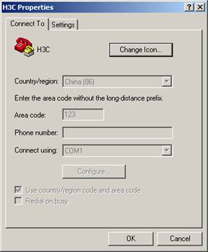
Figure 1-1 Properties dialog box
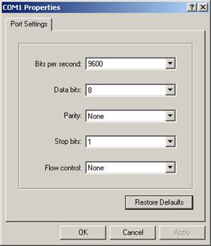
Figure 1-2 Console port configuration dialog box
Step 5: Click the <Disconnect> button to disconnect the HyperTerminal from the switch and then click the <Connect> button to reconnect the HyperTerminal to the switch, as shown in Figure 1-3.

Figure 1-3 Connect and disconnect buttons
& Note:
The new baud rate takes effect only after you disconnect and reconnect the HyperTerminal program.
Step 6: Press <Enter> to start downloading the program. The system displays the following information:
Now please start transfer file with XMODEM protocol.
If you want to exit, Press <Ctrl+X>.
Loading ...CCCCCCCCCC
Step 7: Choose [Transfer/Send File] in the HyperTerminal’s window, and click <Browse> in pop-up dialog box, as shown in Figure 1-4. Select the software you need to download, and set the protocol to XMODEM.
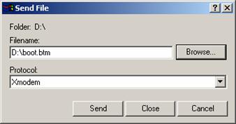
Figure 1-4 Send file dialog box
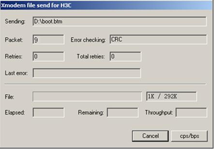
Step 8: Click <Send>. The system displays the page, as shown in Figure 1-5.
Step 9: After the download completes, the system displays the following information:
Loading ...CCCCCCCCCC done!
Step 10: Reset HyperTerminal’s baud rate to 9600 bps (refer to Step 4 and 5). Then, press any key as prompted. The system will display the following information when it completes the loading.
Bootrom updating.....................................done!
& Note:
l If the HyperTerminal’s baud rate is not reset to 9600 bps, the system prompts "Your baudrate should be set to 9600 bps again! Press enter key when ready".
l You need not reset the HyperTerminal’s baud rate and can skip the last step if you have chosen 9600 bps. In this case, the system upgrades Boot ROM automatically and prompts “Bootrom updating now.....................................done!”.
III. Loading host software
Follow these steps to load the host software:
Step 1: Select <1> in Boot Menu and press <Enter>. The system displays the following information:
1. Set TFTP protocol parameter
2. Set FTP protocol parameter
3. Set XMODEM protocol parameter
0. Return to boot menu
Enter your choice(0-3):
Step 2: Enter 3 in the above menu to download the host software using XMODEM.
The subsequent steps are the same as those for loading the Boot ROM software, except that the system gives the prompt for host software loading instead of Boot ROM loading.
1.2.3 Loading Software Using TFTP through Ethernet Port
I. Introduction to TFTP
TFTP, one protocol in TCP/IP protocol suite, is used for trivial file transfer between client and server. It uses UDP to provide unreliable data stream transfer service.
II. Loading Boot ROM software
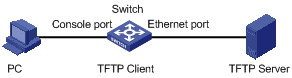
Figure 1-6 Local loading using TFTP
Step 1: As shown in Figure 1-6, connect the switch through an Ethernet port to the TFTP server, and connect the switch through the Console port to the configuration PC.
& Note:
You can use one PC as both the configuration device and the TFTP server.
Step 2: Run the TFTP server program on the TFTP server, and specify the path of the program to be downloaded.
![]() Caution:
Caution:
TFTP server program is not provided with the H3C Series Ethernet Switches.
Step 3: Run the HyperTerminal program on the configuration PC. Start the switch. Then enter the Boot Menu.
At the prompt "Enter your choice(0-5):" in the Boot Menu, press <Ctrl+U>, and then press <Enter> to enter the Boot ROM update menu shown below:
SRPG bootrom update menu:
1. Set TFTP protocol parameter
2. Set FTP protocol parameter
3. Set XMODEM protocol parameter
0. Return to boot menu
Enter your choice(0-3):
Step 4: Enter 1 to in the above menu to download the Boot ROM software using TFTP. Then set the following TFTP-related parameters as required:
Load File name :S7500.btm
Switch IP address :1.1.1.2
Server IP address :1.1.1.1
Step 5: Press <Enter>. The system displays the following information:
Are you sure you want update SRPG bootrom?Yes or No(Y/N)
Step 6: Enter Y to start file downloading or N to return to the Bootrom update menu. If you enter Y, the system begins to download and update the Boot ROM software. Upon completion, the system displays the following information:
Prepare for loading...OK!
Loading........................................done
Bootrom updating..........done!
III. Loading host software
Follow these steps to load the host software.
Step 1: Select <1> in Boot Menu and press <Enter>. The system displays the following information:
1. Set TFTP protocol parameter
2. Set FTP protocol parameter
3. Set XMODEM protocol parameter
0. Return to boot menu
Enter your choice(0-3):3
Step 2: Enter 1 in the above menu to download the host software using TFTP.
The subsequent steps are the same as those for loading the Boot ROM program, except that the system gives the prompt for host software loading instead of Boot ROM loading.
![]() Caution:
Caution:
When loading Boot ROM and host software using Boot menu, you are recommended to use the PC directly connected to the device as TFTP server to promote upgrading reliability.
1.2.4 Loading Software Using FTP through Ethernet Port
I. Introduction to FTP
FTP is an application-layer protocol in the TCP/IP protocol suite. It is used for file transfer between server and client, and is widely used in IP networks.
You can use the switch as an FTP client or a server, and download software to the switch through an Ethernet port. The following is an example.
II. Loading Process Using FTP Client
l Loading Boot ROM software
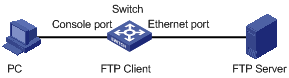
Figure 1-7 Local loading using FTP client
Step 1: As shown in Figure 1-7, connect the switch through an Ethernet port to the FTP server, and connect the switch through the Console port to the configuration PC.
& Note:
You can use one computer as both configuration device and FTP server.
Step 2: Run the FTP server program on the FTP server, configure an FTP user name and password, and copy the program file to the specified FTP directory.
Step 3: Run the HyperTerminal program on the configuration PC. Start the switch. Then enter the Boot Menu.
At the prompt "Enter your choice(0-5):" in the Boot Menu, press <Ctrl+U>, and then press <Enter> to enter the Boot ROM update menu shown below:
SRPG bootrom update menu:
1. Set TFTP protocol parameter
2. Set FTP protocol parameter
3. Set XMODEM protocol parameter
0. Return to boot menu
Enter your choice(0-3):
Step 4: Enter 2 in the above menu to download the Boot ROM software using FTP. Then set the following FTP-related parameters as required:
Load File name :S7500.btm
Switch IP address :10.1.1.2
Server IP address :10.1.1.1
FTP User Name :7500
FTP User Password :abc
Step 5: Press <Enter>. The system displays the following information:
Are you sure you want update SRPG bootrom?Yes or No(Y/N)
Step 6: Enter Y to start file downloading or N to return to the Bootrom update menu. If you enter Y, the system begins to download and update the program. Upon completion, the system displays the following information:
Prepare for loading...OK!
Loading........................................done
Bootrom updating..........done!
l Loading host software
Follow these steps to load the host software:
Step 1: Select <1> in Boot Menu and press <Enter>. The system displays the following information:
1. Set TFTP protocol parameter
2. Set FTP protocol parameter
3. Set XMODEM protocol parameter
0. Return to boot menu
Enter your choice(0-3):
Enter 2 in the above menu to download the host software using FTP.
The subsequent steps are the same as those for loading the Boot ROM program, except for that the system gives the prompt for host software loading instead of Boot ROM loading.
![]() Caution:
Caution:
When loading Boot ROM and host software using Boot menu, you are recommended to use the PC directly connected to the device as TFTP server to promote upgrading reliability.
1.3 Remote Software Loading
If your terminal is not directly connected to the switch, you can telnet to the switch, and use FTP or TFTP to load Boot ROM and host software remotely.
1.3.1 Remote Loading Using FTP
I. Loading Process Using FTP Client
1) Loading Boot ROM
As shown in Figure 1-8, a PC is used as both the configuration device and the FTP server. You can telnet to the switch, and then execute the FTP commands to download the Boot ROM program s7500.btm from the remote FTP server (with an IP address 10.1.1.1) to the switch.
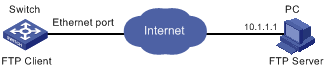
Figure 1-8 Remote loading using FTP
Step 1: Download the software to the switch using FTP commands.
<H3C> ftp 10.1.1.1
Trying ...
Press CTRL+K to abort
Connected.
220 WFTPD 2.0 service (by Texas Imperial Software) ready for new user
User(none):abc
331 Give me your password, please
Password:
230 Logged in successfully
[ftp] get s7500.btm
200 Port command okay.
150 Opening ASCII mode data connection for s7500.btm.
...226 Transfer complete.
FTP: 1177900 byte(s) received in 4.594 second(s) 256.39K byte(s)/sec.
[ftp] bye
& Note:
When using different FTP server software on PC, different information will be output to the switch.
Step 2: Update the Boot ROM program on SRPU of the switch.
<H3C> boot bootrom s7500.btm slot 0
This will update BootRom file on board 0 . Continue? [Y/N] y
Board 0 upgrading BOOTROM, please wait...
Upgrade board 0 BOOTROM succeeded!
Step 3: Restart the switch.
<H3C> reboot
& Note:
Before restarting the switch, make sure you have saved all other configurations that you want, so as to avoid losing configuration information.
2) Loading host software
Loading the host software is the same as loading the Boot ROM program, except for that the file to be downloaded is the host software file, and that you need to use the boot boot-loader command to select the host software at reboot of the switch.
After the above operations, the Boot ROM and host software loading is completed.
Pay attention to the following:
l The loading of Boot ROM and host software takes effect only after you restart the switch with the reboot command.
l If the space of the Flash memory is not enough, you can delete the useless files in the Flash memory before software downloading.
l No power-down is permitted during software loading.
II. Loading Process Using FTP Server
As shown in Figure 1-9, the switch is used as the FTP server. You can telnet to the switch, and then execute the FTP commands to download the Boot ROM program s7500.btm from the switch.
1) Loading Boot ROM
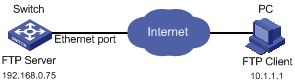
Figure 1-9 Remote loading using FTP server
Step 1: As shown in Figure 1-9, connect the switch through an Ethernet port to the PC (with IP address 10.1.1.1)
Step 2: Configure the IP address of VLAN 1 on the switch to 192.168.0.75, and subnet mask to 255.255.255.0.
& Note:
You can configure the IP address for any VLAN on the switch for FTP transmission. However, before configuring the IP address for a VLAN interface, you have to make sure whether the IP addresses of this VLAN and PC are routable.
<H3C> system-view
System View: return to User View with Ctrl+Z.
[H3C] interface Vlan-interface 1
[H3C-Vlan-interface1] ip address 192.168.0.75 255.255.255.0
Step 3: Enable FTP service on the switch, configure the FTP user name to test, password to pass, and directory to FLASH root directory.
[H3C-Vlan-interface1] quit
[H3C] ftp server enable
[H3C] local-user test
New local user added.
[H3C-luser-test] password simple pass
[H3C-luser-test] service-type ftp ftp-directory flash:/
Step 4: Enable FTP client software on PC. Refer to Figure 1-10 for the command line interface in Windows operating system.
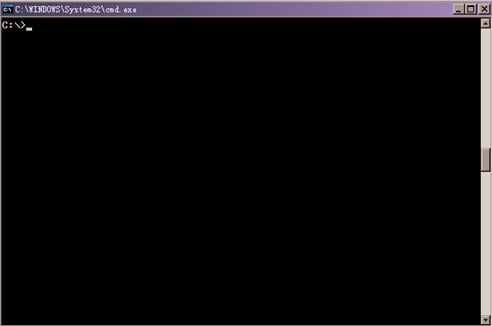
Figure 1-10 Command line interface
Step 5: Enter cd in the interface to switch to the path that the Boot ROM upgrade file is to be stored, and assume the name of the path is “D:\Bootrom”, as shown in Figure 1-11.
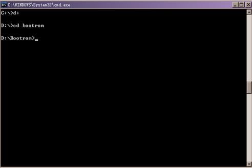
Figure 1-11 Switch to Boot ROM
Step 6: Enter “ftp 192.168.0.75” and enter the user name test, password pass, as shown in Figure 1-12, to log on the FTP server.
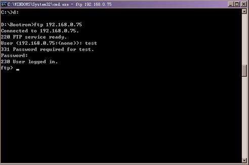
Figure 1-12 Log on the FTP server
Step 7: Use the put command to upload the file s7500.btm to the switch, as shown in Figure 1-13.
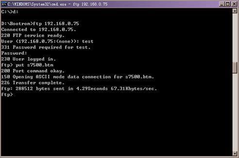
Figure 1-13 Upload file s7500.btm to the switch
Step 8: Configure s7500.btm to be the Boot ROM at reboot, and then restart the switch.
<H3C> boot bootrom s7500.btm slot 0
This will update BootRom file on board 0 . Continue? [Y/N] y
Board 0 upgrading BOOTROM, please wait...
Upgrade board 0 BOOTROM succeeded!
<H3C> reboot
When rebooting the switch, use the file s7500.btm as Boot ROM to finish Boot ROM loading.
2) Loading host software
Loading the host software is the same as loading the Boot ROM program, except for that the file to be downloaded is the host software file, and that you need to use the boot boot-loader command to select the host software at reboot of the switch.
& Note:
l The steps listed above are performed in the Windows operating system, if you use other FTP client software, refer to the corresponding user’s guide before operation.
l Only the configurations steps concerning loading are illustrated here, for detailed description on the corresponding configuration commands, refer to the chapter “FTP and TFTP”.
1.3.2 Remote Loading Using TFTP
The remote loading using TFTP is similar to that using FTP. The only difference is that TFTP is used instead off FTP to load software to the switch, and the switch can only act as a TFTP client.
![]() Caution:
Caution:
l SRPU software and LPU (line processing unit) software must be identical. Otherwise S7500 Ethernet Switches cannot work normally.
l To keep the software of SRPU and LPU identical, you need to restart the LPU after you upgrade the host software of the SRPU of the S7500 series Ethernet switches.
l S7506R switches feature the double SRPUs and active-standby switchover function. If a switch possesses two SRPUs, with the active-standby switchover function enabled, you can in turn upgrade and restart the two SRPUs with one SRPU being active. Although SRPU can be upgraded through hot backup, because the LPU must be restarted to keep identical with the SRPU’s software, your services will still be interrupted during the LPU restart period. Therefore, you are recommended to restart the whole switch straight after you upgrade the host software of the SRPU of the S7506R switch.
Chapter 2 Basic System Configuration and Debugging
When configuring basic system configuration and debugging, go to these sections for information you are interested in:
l Displaying the System Status
2.1 Basic System Configuration
2.1.1 Basic System Configuration Task List
Complete these tasks to configure basic system configuration:
|
Task |
Remarks |
|
— |
|
|
Optional |
|
|
Optional |
|
|
Optional |
|
|
Optional |
|
|
Optional |
|
|
— |
|
|
— |
2.1.2 Entering System View from User View
|
To do… |
Use the command… |
Remarks |
|
Enter system view from user view |
system-view |
— |
2.1.3 Setting the System Name of the Switch
|
To do… |
Use the command… |
Remarks |
|
Enter system view |
system-view |
— |
|
Set the system name of the switch |
sysname sysname |
Optional By default, the name is H3C. |
2.1.4 Setting the Date and Time of the System
|
To do… |
Use the command… |
Remarks |
|
Set the current date and time of the system |
clock datetime HH:MM:SS YYYY/MM/DD |
Optional |
2.1.5 Setting the Local Time Zone
This configuration task is to set the name of the local time zone and the difference between the local time zone and the standard UTC (universal time coordinated) time.
Follow the step to set the local time zone:
|
To do… |
Use the command… |
Remarks |
|
Set the local time zone |
clock timezone zone-name { add | minus } HH:MM:SS |
Optional By default, it is the UTC time zone. |
2.1.6 Setting the Daylight Saving Time
This configuration task is to set the name, time range (start time and end time), and time offset of the daylight saving time. The operation here saves you from manually adjust the system time.
l When the system reaches the specified start time, it automatically adds the specified offset to the current time, so as to toggle the system time to the daylight saving time.
l When the system reaches the specified end time, it automatically subtracts the specified offset from the current time, so as to toggle the daylight saving time to normal system time.
Follow the step to set the daylight saving time:
|
To do… |
Use the command… |
Remarks |
|
Set the name and time range of the daylight saving time |
clock summer-time zone-name one-off start-time start-date end-time end-date offset-time clock summer-time zone-name repeating { start-time start-date end-time end-date | start-time start-year start-month start-week start-day end-time end-year end-month end-week end-day } offset-time |
Optional Available in user view |
2.1.7 Setting the CLI Language Mode
|
To do… |
Use the command… |
Remarks |
|
Set the CLI language mode |
language-mode { chinese | english } |
Optional By default, the command line interface (CLI) language mode is English. |
2.1.8 Returning from Current View to Lower Level View
|
To do… |
Use the command… |
Remarks |
|
Return from current view to lower level view |
quit |
This operation will result in exiting the system if current view is user view. |
2.1.9 Returning from Current View to User View
|
To do… |
Use the command… |
Remarks |
|
Return from current view to user view |
return |
The composite key <Ctrl+Z> has the same effect with the return command. |
2.2 Displaying the System Status
|
To do… |
Use the command… |
Remarks |
|
Display the current date and time of the system |
display clock |
Available in any view |
|
Display the version of the system |
display version |
|
|
Display the information about user terminal interfaces |
display users [ all ] |
|
|
Display the debugging status |
display debugging [ interface interface-type interface-number ] [ module-name ] |
2.3 System Debugging
2.3.1 Enabling/Disabling System Debugging
The Ethernet switch provides a variety of debugging functions. Most of the protocols and features supported by the Ethernet switch are provided with corresponding debugging functions. These debugging functions are a great help for you to diagnose and troubleshoot your switch system.
The output of debugging information is controlled by two kinds of switches:
l Protocol debugging, which controls whether the debugging information of a protocol is output.
l Terminal display, which controls whether the debugging information is output to a user screen.
The relation between the two switches is as follows:
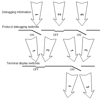
Figure 2-1 Debugging information output
You can use the following commands to operate the two kinds of switches.
Perform the following operations in user view.
Follow these steps to enable debugging and terminal display:
|
To do… |
Use the command… |
Remarks |
|
Enable system debugging |
debugging { all [ timeout interval ] | module-name debugging-option } |
By default, all debugging is disabled in the system. Because the output of debugging information will affect the efficiency of the system, disable your debugging after you finish it. |
|
Enable terminal display for debugging |
terminal debugging |
By default, terminal display for debugging is disabled. |
2.3.2 Displaying Debugging Status
|
Use the command… |
Remarks |
|
|
Display all enabled debugging on the specified device |
display debugging [ interface interface-type interface-number ] [ module-name ] |
You can execute the display command in any view. |
2.3.3 Displaying Operating Information about Modules in System
When your Ethernet switch is in trouble, you may need to view a lot of operating information to locate the problem. Each functional module has its own operating information display command(s). You can use the command here to display the current operating information about the modules (settled when this command is designed) in the system for troubleshooting your system.
Perform the following operation in any view.
|
To do… |
Use the command… |
Remarks |
|
Display the current operation information about the modules in the system. |
display diagnostic-information [ module-name ] |
You can execute this command twice and find the difference between the two executing results to locate the problem. |
Chapter 3 Network Connectivity Test
When configuring network connectivity test, go to these sections for information you are interested in:
l ping
l tracert
3.1 Network Connectivity Test
3.1.1 ping
You can use the ping command to check the network connectivity and the reachability of a host.
|
Operation |
Command |
|
Support IP protocol |
ping [ -a ip-address | -c count | -d | -f | -h ttl | -i interface-type interface-number | -n | - p pattern | -q | -r | -s packetsize | -t timeout | -tos tos | -v | ip ]* host-ip |
|
Support IPX protocol |
ping ipx ipx-address [ -c count | -s packetsize | -t timeout ]* |
|
Support CLNS protocol |
ping clns nsap-address |
This command can output the following results:
l Response status for each ping packet. If no response packet is received within the timeout time, the message "Request time out" is displayed. Otherwise, the number of data bytes, packet serial number, TTL (time to live) and response time of the response packet are displayed.
l Final statistics, including the numbers of sent packets and received response packets, the irresponsive packet percentage, and the minimum, average and maximum values of response time.
3.1.2 tracert
You can use the tracert command to trace the gateways a packet passes during its journey from the source to the destination. This command is mainly used to check the network connectivity. It can help you locate the trouble spot of the network.
The executing procedure of the tracert command is as follows: First, the source host sends a data packet with the TTL of 1, and the first hop device returns an ICMP error message indicating that it cannot forward this packet because of TTL timeout. Then, the source host resends the packet with the TTL of 2, and the second hop device also returns an ICMP TTL timeout message. This procedure goes on and on until the packet gets to the destination. During the procedure, the system records the source address of each ICMP TTL timeout message in order to offer the path that the packet passed through to the destination.
|
Operation |
Command |
|
Support IP protocol |
tracert [ -a source-ip | -f first-TTL | -m max-TTL | -p port | -q num-packet | -w timeout ] * host |
|
Support CLNS protocol |
tracert clns [ -m max-TTL | -n num-packet | -t timeout | -v ]* nsap-address |
Chapter 4 Device Management
When configuring device management, go to these sections for information you are interested in:
l Introduction to Device Management
l Device Management Configuration
l Configuring Pause Frame Protection Mechanism
l Configuring Layer 3 Connectivity Detection
l Configuring Queue Traffic Monitoring
l Configuring Error Packets Monitoring
l Displaying the Device Management Configuration
l Remote Switch Update Configuration Example
& Note:
When different engines work together with a chassis, note that:
If the Salience III series engines and Salience III Edge engines work with the S7506R chassis without the XGbus silkscreen, the four SFP interfaces on the engine do not work.
If a Salience III engine or a Salience III Edge engine works with S7506R XGbus chassis, the four SFP interfaces on the engine all work normally.
When two Salience III engines or two Salience III Edge engines are inserted into the S7506R XGbus chassis,
l The first two SFP interfaces of the primary board and the first two SFP interfaces of the secondary board work normally. Services will not be interrupted during active-standby switchover.
l The last two SFP interfaces on the primary board and the last two interfaces on the secondary board do not work, and you can not see these four interfaces through command line interface.
l When the secondary board is inserted, configurations on the last two SFP interfaces of the primary board will not be sent to the first two SFP interfaces of the secondary board automatically, and you need to do this manually.
4.1 Introduction to Device Management
The device management function of the Ethernet switch can report the current status and event-debugging information of the boards to you. Through this function, you can maintain and manage your physical device, and restart the system when some functions of the system are abnormal.
4.2 Device Management Configuration
4.2.1 Device Management Configuration Task List
Complete these tasks to configure device management:
|
Task |
Remarks |
|
— |
|
|
Optional |
|
|
Optional |
|
|
Optional |
|
|
Optional |
|
|
Optional |
|
|
Optional |
|
|
Optional |
|
|
Optional |
4.2.2 Restarting the Ethernet Switch
You can perform the following operation in user view when the switch is in trouble or needs to be restarted.
& Note:
When rebooting, the system checks whether there is any configuration change. If there is, it prompts you to indicate whether or not to proceed. This prevents you from losing your original configuration due to oblivion after system reboot.
Follow the step to restart the Ethernet switch:
|
To do… |
Use the command… |
Remarks |
|
Restart the Ethernet switch |
reboot |
— |
4.2.3 Rebooting a Card of Ethernet Switch
It would be necessary to reset a card of Ethernet switch when failure occurs.
Follow the step to reset a card:
|
To do… |
Use the command… |
Remarks |
|
Reset a card of Ethernet switch |
reboot [ slot slot-number ] |
Optional |
The range of slot-number varies with the specific product type: for S7502, it is 0~2; for S7503, it is 0~3; for S7506, it is 0~6; for S7506R, it is 0~7. Choosing 0 means that you will reset the SRPU board, which is equivalent to resetting the system.
4.2.4 Scheduling a Reboot on the Switch
After you schedule a reboot on the switch, the switch will reboot at the specified time.
Follow these steps to schedule a reboot on the switch
|
To do… |
Use the command… |
Remarks |
|
Schedule a reboot on the switch, and set the reboot date and time |
schedule reboot at hh:mm [ yyyy/mm/dd ] |
Optional |
|
Schedule a reboot on the switch, and set the reboot waiting delay |
schedule reboot delay { hhh:mm | mmm } |
Optional |
& Note:
There is at most one minute defer for scheduled reboot, that is, the switch will reboot within one minute after reaching the specified reboot date and time.
4.2.5 Specifying the APP to be Adopted at Reboot
APP is the host software of the switch. If multiple APPs exist in the Flash memory, you can use the command here to specify the one that will be adopted when the switch reboots.
The S7500 series Ethernet switches feature double SRPUs. When both the active and standby SRPUs need to be upgraded, you need to specify the APP file used for the next startup for the active SRPU and the standby SRPU respectively. Note that, you must specify the APP file for the active SRPU from the Flash or CF card of the active SRPU, and that for the standby SRPU from the Flash or CF card of the standby SRPU.
Follow the step to specify the APP to be adopted at reboot:
|
To do… |
Use the command… |
Remarks |
|
Specify the APP to be adopted at reboot |
boot boot-loader { primary | backup } file-url |
Optional Available in user view |
4.2.6 Updating the Boot ROM
You can use the Boot ROM application saved in the Flash memory of the switch to update the running Boot ROM application. With this command, a remote user can conveniently update the Boot Rom by uploading the Boot ROM to the switch through FTP and running this command. The Boot ROM can be used when the switch reboots.
Follow the step to update the Boot ROM:
|
To do… |
Use the command… |
Remarks |
|
Update the Boot ROM |
boot bootrom file-url slot slot-list |
Optional Available in user view |
4.2.7 Upgrading Boot ROM along with the Upgrade of ARP
Upgrading Boot ROM along with ARP can ensure the best matching between the version of current primary board and the version of Boot ROM, so as to avoid the mal-operations of some functions and features caused by unmatched versions.
This feature supports two upgrade types:
l Use the current boot file as the upgrade file of Boot ROM.
l Specify the ARP file as the upgrade file of Boot ROM.
Follow the step to configure to upgrade Boot ROM:
|
To do… |
Use the command… |
Remarks |
|
Use the current boot file to upgrade Boot ROM |
boot bootrom default [ slot slot-list ] |
Optional |
l If you do not specify the slot number to upgrade in the boot bootrom command, the system will upgrade all the cards working normally by default.
l After you specify the boot file of the primary board, if you want to upgrade Boot ROM, the system will upgrade all cards working normally by default. During the upgrade process, the system will prompt you to confirm whether to upgrade or not.
4.2.8 Setting Card Temperature Threshold
The switch system alarms when the temperature on a card exceeds a specified temperature range.
Follow the step to set card temperature threshold:
|
To do… |
Use the command… |
Remarks |
|
Set card temperature threshold |
temperature-limit slot-number down-value up-value |
Optional |
4.2.9 Enabling/Disabling RDRAM
Using the following command, yon can enable or disable RDRAM (Rambus Dynamic Random Access Memory) of the device.
Follow these steps to enable/disable RDRAM:
|
To do… |
Use the command… |
Remarks |
|
Enter system view |
system-view |
— |
|
Enable RDRAM of the device |
rdram enable |
Optional By default, RDRAM is disabled. |
|
Disable RDRAM of the device |
rdram disable |
4.2.10 Enabling System Load Sharing
With system load sharing enabled, after an LPU receives traffic to be cross-card forwarded, load sharing is performed between the active SRPU and the standby SRPU.
Follow these steps to enable system load sharing:
|
To do… |
Use the command… |
Remarks |
|
Enter system view |
system-view |
— |
|
Enable system load sharing function |
loadsharing enable |
Required By default, system load sharing is disabled. |
& Note:
l Only unicast traffic supports load sharing.
l Only the Salience III or Salience III Plus SRPU supports load sharing.
l Only LPU of XGbus type supports load sharing.
4.3 Configuring Pause Frame Protection Mechanism
Pause frames, which can be utilized as packets to attack a network, are used in traffic controlling. A switch that has pause frame protection mechanism enabled discards the detected pause frames that are utilized to attack the network it resides and logs these attacks in the logbuffer. If the switch experiences successive pause frame attacks, it sends messages to the console to warn users.
![]() Caution:
Caution:
Only A type cards support pause frame protection mechanism and the related commands. A type cards include: LS81FT48A, LS81FM24A, LS81FS24A, LS81GB8UA, and LS81GT8UA.
4.3.1 Pause Frame Protection Mechanism Configuration Task
The following describes the configuration tasks of Pause Frame protection mechanism.
Follow these steps to configure pause frame protection mechanism:
|
To do… |
Use the command… |
Remarks |
|
Enter system view |
system-view |
— |
|
Enable pause frame protection mechanism |
pause-protection enable slot slot-number |
Required Pause frame protection mechanism is disabled by default. |
4.3.2 Pause Frame Protection Mechanism Configuration Example
I. Network requirements
Enable pause frame protection mechanism on the card in Slot 7 of the switch.
II. Configuration procedure
1) Enter system view.
<H3C> system-view
[H3C]
2) Enable pause frame protection mechanism on the card seated in slot 7.
[H3C] pause-protection enable slot 7
4.4 Configuring Layer 3 Connectivity Detection
4.4.1 Introduction to layer 3 connectivity detection
The function that detects layer 3 connectivity is implemented as follows. Local devices send ARP request packets continuously to the IP addresses of the devices to be detected. Users can then locate, solve, and log link problems by monitoring the peer devices through the received ARP response packets.
& Note:
This function requires no Layer 3 device existing between the local peer and the remote peer.
4.4.2 Layer 3 Connectivity Detection Configuration Task
& Note:
Before performing this configuration, make sure the physical link between the local peer and the remote peer is correct, and the related VLAN interfaces are assigned with correct IP addresses.
Follow these steps to configure Layer 3 connectivity detection:
|
To do… |
Use the command… |
Remarks |
|
Enter system view |
system-view |
— |
|
Enter Ethernet interface view |
interface interface-type interface-number |
— |
|
Enable Layer 3 connectivity detection function |
uplink monitor ip ip-address |
Required |
|
Display information about Layer 3 connectivity between the local device and the remote device |
display uplink monitor |
Optional You can execute the display command in any view. |
4.4.3 Layer 3 Connectivity Detection Configuration Example
I. Network requirements
l The physical link between the local peer and the remote peer is correct. The local peer port that is used to connect is Ethernet 4/0/1.
l The IP address of the Lay 3 interface of the remote peer is 1.1.1.1.
II. Configuration procedure
# Enter system view.
<H3C> system-view
[H3C]
# Enter Ethernet interface view.
[H3C] interface Ethernet 4/0/1
# Enable Layer 3 connectivity detection on Ethernet 4/0/1 interface and specify the IP address of the device (1.1.1.1) to be detected.
[H3C-Ethernet4/0/1] uplink monitor ip 1.1.1.1
4.5 Configuring Queue Traffic Monitoring
Upon enabling queue traffic monitoring on a switch, the switch monitors the queue traffic and relieves blocks in the output queue of its interfaces.
The criterion used to distinguish a block is that the queue is full, and the traffic of the corresponding interface is less than the specified threshold.
4.5.1 Queue Traffic Monitoring Configuration Task
The following describes configuration tasks of queue traffic monitoring.
Follow these steps to configure queue traffic monitoring:
|
To do… |
Use the command… |
Remarks |
|
Enter system view |
system-view |
— |
|
Enable queue traffic monitoring |
qe monitor enable |
Required This function is enabled by default. |
|
Set the overall traffic threshold |
qe monitor overflow-threshold threshold |
Optional 300,000,000 bps by default. |
4.5.2 Queue Traffic Monitoring Configuration Example
I. Network requirements
l Enable queue traffic monitoring.
l Set the overall traffic threshold used in queue traffic monitoring to 90 Mbps.
II. Configuration procedure
# Enter system view.
<H3C> system-view
[H3C]
# Enable queue traffic monitoring.
[H3C] qe monitor enable
# Set the overall traffic threshold used in queue traffic monitoring to 90 Mbps.
[H3C] qe monitor overflow-threshold 90000000
4.6 Configuring Error Packets Monitoring
If the switch receives a great number of error packets, it will not be able to send/receive packets properly. With error packets monitoring enabled, the switch collects information about received error packets regularly. If error packets are detected, it takes protection measures to ensure that its interfaces send/receive packets properly.
4.6.1 Error Packets Monitoring Configuration Task
The following describes configuration tasks of error packets monitoring.
Follow these steps to configure error packets monitoring:
|
To do… |
Use the command… |
Remarks |
|
Enter the system view |
system-view |
— |
|
Set the interval for detecting error packets |
qe monitor errpkt check-time interval |
Optional Defaults to 5 seconds. |
|
Enter Ethernet interface view |
interface interface-type interface-number |
— |
|
Enable error packets monitoring |
qe monitor errpkt { all | none | runt } |
Required. If you specify the keyword all in the command, the switch detects all error packets on current interface. If you specify the keyword runt, the switch only detects error packets that are of runt type on current interface. If you specify the keyword none, the switch does not detect the error packets on current interface. |
4.6.2 Error Packets Monitoring Configuration Example
I. Network requirements
l Enable error packets monitoring on Ethernet 4/0/1 interface and only the packets that are of runt type are concerned.
l Set the interval for detecting error packets to 50 seconds.
II. Configuration procedure
# Enter system view.
<H3C> system-view
[H3C]
# Set the interval for detecting error packets to 50 seconds.
[H3C] qe monitor errpkt check-time 50
# Enter Ethernet interface view of Ethernet 4/0/1.
[H3C] interface Ethernet 4/0/1
[H3C-Ethernet4/0/1]
# Specify only detect current interface for error packets of runt type.
[H3C-Ethernet4/0/1] qe monitor errpkt runt
4.7 Displaying the Device Management Configuration
After the above configurations, you can execute the display command in any view to display the operating status of the device management to verify the configuration effects.
Follow these steps to display the operating status of the device management:
|
To do… |
Use the command… |
Remarks |
|
Display the APP to be adopted at reboot |
display boot-loader |
Available in any view. |
|
Display the module type and operating status of each board |
display device [ detail | [ shelf shelf-no ] [ frame frame-no ] [ slot slot-number ] ] |
|
|
Display information about environment used by a switch |
display environment |
|
|
Display the operating status of the built-in fan |
display fan [ fan-id ] |
|
|
Display the usage of s switch |
display cpu [ slot slot-number ] |
|
|
Display memory usage of a switch |
display memory [ slot slot-number | limit ] |
|
|
Display the operating status of the power supply |
display power [ power-id ] |
4.8 Remote Switch Update Configuration Example
I. Network requirements
Telnet to the switch from a PC remotely and download applications from the FTP server to the Flash memory of the switch to remotely update the switch software by using the device management commands through CLI.
The switch acts as the FTP client, and the remote PC serves as both the configuration PC and the FTP server.
Perform the following configuration on the FTP server.
l Configure an FTP user, whose name and password are switch and hello respectively. Authorize the user with the read-write right of the Switch directory on the PC.
l Make appropriate configuration so that the IP address of a VLAN interface on the switch is 1.1.1.1, the IP address of the PC is 2.2.2.2, and the switch and the PC is reachable to each other.
The host software switch.app and the Boot ROM file boot.btm of the switch are stored into the directory of the switch. Use FTP to download the switch.app and boot.btm files from the FTP server to the switch.
II. Network diagram
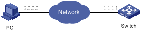
Figure 4-1 Network diagram of FTP configuration
III. Configuration procedure
1) Configure the following FTP server–related parameters on the PC: an FTP user with the username and password as switch and hello respectively, and specify the working directory of the user as Switch. The detailed configuration is omitted here.
2) Configure the switch as follows:
# On the switch, configure a level 3 telnet user with the username and password as user and hello respectively. Authentication by user name and password is required for the user.
& Note:
Refer to Login Configuration and Login Commands in this manual for configuration commands and steps about telnet user.
# Execute the telnet command on the PC to log into the switch. The following prompt appears:
<H3C>
![]() Caution:
Caution:
If the Flash memory of the switch is not sufficient, delete the original applications in it before downloading the new ones.
# Initiate an FTP connection with the following command in user view. Input the correct user name and password to log into the FTP server.
<H3C> ftp 2.2.2.2
Trying ...
Press CTRL+K to abort
Connected.
220 WFTPD 2.0 service (by Texas Imperial Software) ready for new user
User(none):switch
331 Give me your password, please
Password:
230 Logged in successfully
[ftp]
# Execute the get command to download the switch.app and boot.btm files on the FTP server to the Flash memory of the switch.
[ftp] get switch.app
[ftp] get boot.btm
# Execute the quit command to terminate the FTP connection and return to user view.
[ftp] quit
<H3C>
# Update the Boot ROM.
<H3C> boot bootrom boot.btm slot 0
This will update BootRom file on board 0 . Continue? [Y/N] y
Board 0 upgrading BOOTROM, please wait...
Upgrade board 0 BOOTROM succeeded!
# Specify the downloaded application program as the host software to be adopted when the switch starts next time. Then restart the switch to update the host software of the switch.
<H3C> boot boot-loader primary switch.app
The specified file will be booted next time!
<H3C> display boot-loader
The primary app to boot of board 0 at the next time is: flash:/switch.app
The backup app to boot of board 0 at the next time is: flash:/old.app
The app to boot of board 0 at this time is: flash:/old.app
<H3C> reboot
System is checking configuration now. Please wait ...
This command will reboot the system. The current configuration has not been saved and will be lost if you continue. Continue? [Y/N] y