- Table of Contents
-
- H3C S7500 Series Operation Manual(Release 3100 Series)-(V1.04)
- 00-1Cover
- 00-2Overview
- 01-CLI Configuration
- 02-Login Configuration
- 03-Configuration File Management Configuration
- 04-VLAN Configuration
- 05-Extended VLAN Application Configuration
- 06-IP Address-IP Performance-IPX Configuration
- 07-GVRP Configuration
- 08-QinQ Configuration
- 09-Port Basic Configuration
- 10-Link Aggregation Configuration
- 11-Port Isolation Configuration
- 12-Port Binding Configuration
- 13-DLDP Configuration
- 14-MAC Address Table Configuration
- 15-MSTP Configuration
- 16-Routing Protocol Configuration
- 17-Multicast Configuration
- 18-802.1x Configuration
- 19-AAA-RADIUS-HWTACACS-EAD Configuration
- 20-Traffic Accounting Configuration
- 21-VRRP-HA Configuration
- 22-ARP Configuration
- 23-DHCP Configuration
- 24-ACL Configuration
- 25-QoS Configuration
- 26-Mirroring Configuration
- 27-Cluster Configuration
- 28-PoE Configuration
- 29-UDP-Helper Configuration
- 30-SNMP-RMON Configuration
- 31-NTP Configuration
- 32-SSH Terminal Service Configuration
- 33-File System Management Configuration
- 34-FTP and TFTP Configuration
- 35-Information Center Configuration
- 36-DNS Configuration
- 37-System Maintenance and Debugging Configuration
- 38-HWPing Configuration
- 39-RRPP Configuration
- 40-NAT-Netstream-Policy Routing Configuration
- 41-Telnet Protection Configuration
- 42-Hardware-Dependent Software Configuration
- Related Documents
-
| Title | Size | Download |
|---|---|---|
| 39-RRPP Configuration | 222 KB |
Table of Contents
1.1.3 Basic Principles of RRPP
1.1.4 Typical Networking of RRPP
1.1.5 RRPP on H3C S7500 Series Ethernet Switches
1.2.1 Master Node Configuration Tasks
1.2.2 Master Node Configuration Example
1.3 Transit Node Configuration
1.3.1 Transit Node Configuration Tasks
1.3.2 Transit Node Configuration Example
1.4.1 Edge Node Configuration Tasks
1.4.2 Edge Node Configuration Example
1.5 Assistant Edge Node Configuration
1.5.1 Assistant Edge Node Configuration Tasks
1.5.2 Assistant Edge Node Configuration Example
1.6.1 Single Ring Network Configuration Example
1.6.2 Intersectant Ring Network Configuration Example
Chapter 1 RRPP Configuration
When performing RRPP configuration, go to these sections for information you are interested in:
l Assistant Edge Node Configuration
1.1 RRPP Overview
The Rapid Ring Protection Protocol (RRPP) is a link layer protocol designed for Ethernet rings. RRPP can prevent broadcast storm caused by data loops when the Ethernet rings are healthy, and rapidly restore the communication paths between nodes after a link is disconnected on the Ethernet ring network.
Compared with the spanning tree protocol (STP), RRPP has the following characteristics:
l Dedicated to Ethernet ring topology
l Fast response
1.1.1 Basic Concepts of RRPP
I. Domain
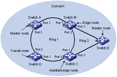
A domain consists of switches with the same domain ID and control VLAN. A domain can consist of multiple Ethernet rings, only one of which is the primary ring and the others are subrings. The ring roles are determined by user configuration.
As shown in Figure 1-1, Domain 1 is an RRPP domain, which consists of Ethernet ring 1 and ring 2. All the nodes on the Ethernet rings belong to the RRPP domain.
II. Ethernet ring
An Ethernet ring is a ring-shaped Ethernet topology, on which a RRPP domain is based. An RRPP domain consists of a primary ring and one or more subrings. In configuration, the level of the primary ring is level 0, and that of the subrings is level 1.
As shown in Figure 1-1, RRPP domain 1 consists of ring 1 and ring 2. If their levels are set to level 0 and level 1 respectively, ring 1 is the primary ring and ring 2 is the subring.
Each ring is in one of the following two states:
l Healthy state: The physical links of the ring network are connected.
l Broken state: A certain physical link is disconnected on the ring network.
III. Control VLAN and data VLAN
l A control VLAN is a special VLAN used to transfer RRPP packets. The port on each switch for connecting the switch with the Ethernet ring belongs to the control VLAN, and only the ports connected to the Ethernet ring can be added to the control VLAN. It is not allowed to configure an IP address for the interface of the control VLAN. You can configure the control VLAN of the primary ring. The control VLAN of the subring is assigned by the system automatically. The ID of the subring control VLAN is the ID of the primary ring control VLAN plus 1.
l A data VLAN is used to transfer data packets. A data VLAN contains the ports connecting the switch with the Ethernet ring network and other ports.
IV. Node
Every switch on an Ethernet ring network is a node. Node roles are as follows:
l Master node: The node that initiates loop detection and prevents data loops is the master node. Each ring has one and only one master node.
l Transit node: All nodes other than the master node on a ring are transit nodes.
l Edge node: A node located on the primary ring and a subring at the same time. An edge node serves as a transit node on the primary ring and an edge node on a subring. In an RRPP domain, there are two edge nodes on a subring. You must specify one of them as an assistant edge node so far the configuration can tell the difference between the edge node and assistant edge node.
The node roles are determined by user configuration. As shown in Figure 1-1, Switch A is the master node on ring 1. Switch B, Switch C, and Switch D are transit nodes on ring 1. Switch B and Switch C are edge nodes because they are both on ring 2. You can specify one of them as an edge node, and the other as an assistant edge node.
V. Primary port and secondary port
The master node and each of the transit nodes are connected to an Ethernet ring through two ports, of which one is the primary port and the other is the secondary port. The node roles are determined by user configuration.
l The primary port and secondary port of the master node
The primary port of the master node transmits the loop detection packet, and the secondary port of the master node receives the loop detection packet.
When an Ethernet ring is in the healthy state, the secondary port of the master node allows only RRPP packets to pass, but logically blocks data packets in data VLANs.
When the Ethernet ring is in the broken state, the secondary port of the master node stops blocking the data VLAN and begins to forwards data packets in data VLANs.
l The primary and secondary ports of a transit node are functionally the same.
The node roles are determined by user configuration. As shown in Figure 1-1, Switch A is the master node of Ring 1. Port 1 and Port 2 of Switch A are the primary port and secondary port respectively. Switch B, Switch C, and Switch D are the transit nodes on ring 1, and their respective port 1 and port 2 are the primary port and secondary port on ring 1.
Subring protocol messages are processed as data packets in the primary ring. Thus, when the secondary port on the master node of the primary ring, or the RRPP ports (including the primary and secondary ports) on the transit node are blocked, both data packets and subring protocol messages cannot pass through the port. After the ports are unblocked, these packets or messages can pass through the ports.
VI. Common port and edge port
Of the two ports connecting an edge node (or assistant edge node) to a subring, one is the common port and the other is the edge port of the node. The common port connects the edge node to the primary ring and a subring at the same time. An edge port is connected only with a subring.
Conceptually, a common port is not treated as a port on the subring. Instead, it is a part of the primary ring. In another word, the common link is a link on the primary ring instead of the subring. Status change of a public link is only reported to the master node of the primary ring and the master node of the subring needs not know about the change.
The node roles are determined by user configuration. As shown in Figure 1-1, Switch B and Switch C are on ring 1 and ring 2 at the same time. Port 2 of Switch B and Port 1 of Switch C connect the primary and a subring, so they are common ports. Port 3 of Switch B and Port 3 of Switch C connect only the subring, so they are edge ports.
VII. MAC address FDB
The Layer 2 forwarding database (FDB) on a switch is updated through the source MAC address auto-learning function of the switch.
VIII. Timer
Two timers, Hello timer and Fail timer, are involved when the master node sends and receives RRPP packets.
l Hello timer: Defines the time interval at which the primary port of the master node sends the health detection packet.
1.1.2 RRPP Packet Type
The following table describes RRPP packet types.
|
Packet type |
Description |
|
HEALTH (HELLO) |
The master node sends the health detection packet (HELLO packet) to detect whether the ring network is complete. |
|
LINK-DOWN |
A transit node sends this packet to notify the master node that a link is DOWN and the physical ring is disconnected. |
|
COMMON- FLUSH-FDB |
The master node sends this packet to tell all the transit nodes to refresh their respective MAC address FDBs. |
|
COMPLETE- FLUSH-FDB |
The master node sends this packet to tell all the transit nodes to refresh their respective MAC address FDBs and unblock the ports in the blocked data VLANs. |
|
EDGE-HELLO |
This packet is generated by the edge node of a subring and received by the assistant edge node in the same subring. The subring uses this packet to check the integrity of the primary ring in the home domain. |
|
MAJOR-FAULT |
This packet is generated by the assistant edge node of a subring. If the assistant edge node does not receive the EDGE-HELLO from the edge node within the specified period, it reports to the edge node that a fault exists in the primary ring of the home domain. |
1.1.3 Basic Principles of RRPP
I. Link DOWN notification mechanism
When detecting a port in the RRPP domain is down, a transit node sends the LINK DOWN packet immediately to the master node. After receiving the LINK DOWN packet, the master node unblocks the data VLAN of the secondary port, and sends the Common Flush packet to tell all transit nodes to refresh their respective MAC address FDBs.
II. Polling mechanism
The primary port of the master node periodically sends the health detection packet in a control VLAN.
l If the secondary port of the master node receives the health detection packet, this indicates that the ring link is complete, and the master node will keep the secondary port blocked.
l If the secondary port of the master node fails to receive the health detection packet within the predefined timeout time, this indicates that a failure has occurred to the ring link. In this case, the master node unblocks the data VLANs on the secondary port, and sends the Common Flush packet to tell all transit nodes to refresh their respective MAC address FDBs.
III. Ring recovery
The master node may detect that the ring has recovered a period time after the RRPP domain port on a transit node becomes UP again. In this period, a temporary data loop may occur in data VLANs, which can cause broadcast storm.
To avoid temporary data loops, when detecting the port through which it connects to the ring network becomes UP again, a transit node blocks the port temporarily (only control VLAN packets are permitted to pass), and keeps the port blocked until it receives the Complete Flush packet from the master node.
1.1.4 Typical Networking of RRPP
To ensure normal RRPP operation, you must configure RRPP correctly. Here are several typical networking applications.
I. Single ring network
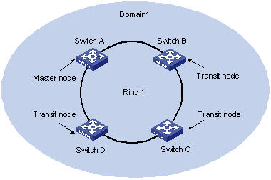
Figure 1-2 Single ring network
There is only one ring in the network topology. In this case, only one RRPP domain is to be defined.
II. Tangent ring networking
Figure 1-3 Tangent ring networking
There are two or more rings in the network topology and only one common node exists between each pair of rings. In this case, one RRPP domain must be defined for each ring.
III. Intersectant ring networking
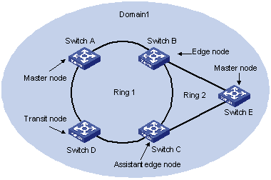
Figure 1-4 Intersectant ring networking
There are two or more rings in the network topology and two common nodes exist between each pair of rings. In this case, only one RRPP domain is to be defined, in which one ring must be defined as the primary ring and the rest as subrings.
1.1.5 RRPP on H3C S7500 Series Ethernet Switches
To employ RRPP on an S7500 series Ethernet switch, make sure that:
l The chassis comes with the silk print XGbus.
l For H3C S7503/S7506/S7506R switches, Salience III series SRPUs (including Salience III, Salience III Plus, and Salience III Edge) are used. Besides, BootROM version 527 (or later) is used.
l For H3C S7502 switches, the CPLD version of the SRPU is not lower than 005.
l The CPLD version of the LPUs is not lower than 005.
Ports that support RRPP are:
l The four Gigabit SFP ports on Salience III Edge/ Salience III engine
l Gigabit SFP ports/10 Gigabit ports on LS81T12PE, LS81P12TE, LS81GP8UB, LS81TGX2, LS81TGX4, LS81T32P, LS81T16P, and LS81GP48 LPUs.
& Note:
l For information about the chassis, SRPU, and LPU of H3C S7503/S7506/S7506R series Ethernet switches, refer to H3C S7500 Series Ethernet Switches Installation Manual.
l For information about the chassis, SRPU, and LPU of H3C S7502 Ethernet switch, refer to H3C S7502 Ethernet Switch Installation Manual.
As for the above-mentioned ports, to make RRPP-related configuration to take effect, you need also to make sure that:
l The ports are Trunk ports and permit packets of data VLANs.
l The ports cannot be aggregation ports.
l MSTP, QinQ, 802.1X or Voice VLAN is not enabled on the ports.
1.2 Master Node Configuration
1.2.1 Master Node Configuration Tasks
Follow these steps to configure the master node:
|
To do… |
Use the command… |
Remarks |
|
Enter system view |
system-view |
— |
|
Create an RRPP domain, and enter RRPP domain view |
rrpp domain domain-id |
Required. The command prompt of RRPP domain view depends on the domain-id you input. |
|
Specify a control VLAN for the RRPP domain |
control-vlan vlan-id |
Required |
|
Specify the current switch as the primary node of a ring, and specify the primary port and the secondary port of the node |
ring ring-id node-mode master [ primary-port pri-port ] [ secondary-port sec-port ] level level-value |
Required. Level 0 identifies the primary ring and level 1 identifies a subring. |
|
Configure RRPP domain timers |
timer hello-timer hello-value fail-timer fail-value |
Optional. By default, the Hello timer is set to 1 second, and the Fail timer to 3 seconds. |
|
Enable an RRPP ring |
ring ring-id enable |
Required |
|
Return to system view |
quit |
— |
|
Enable the RRPP protocol |
rrpp enable |
Required |
|
Display the brief information of all RRPP domains configured on the switch |
display rrpp brief |
Optional. You can execute the display command in any view |
|
Display RRPP configuration details on the switch |
display rrpp verbose domain domain-id [ ring ring-id ] |
|
|
Display RRPP packet statistics of the switch |
display rrpp statistics domain domain-id [ ring ring-id ] |
To clear the RRPP statistics, use the reset rrpp statistics domain domain-id [ ring ring-id ] command.
![]() Caution:
Caution:
l The control VLAN of an RRPP domain cannot be a static VLAN already created on the switch. If you configure a dynamic VLAN as the control VLAN of an RRPP domain, the VLAN becomes a static VLAN automatically.
l You are not recommended to configure a VLAN as both an RRPP control VLAN and a remote-probe VLAN. (Refer to Mirroring part of this manual for information about remote-probe VLAN.)
l You are not recommended to configure a VLAN as both an RRPP control VLAN and an isolate-user-VLAN/sub VLAN. (Refer to Extended VLAN Application part of this manual for information about isolate-user-VLAN and sub VLAN.)
l Before creating an RRPP ring, you need to create the control VLAN.
l When deleting an RRPP domain by using the undo rrpp domain command, make sure no RRPP ring exists in the RRPP domain.
1.2.2 Master Node Configuration Example
I. Network requirements
l Define the switch as a node in RRPP domain 1
l Define VLAN 4092 as the control VLAN
l Define the switch as the master node on primary ring 1 in RRPP domain 1, GigabitEthernet2/0/1 as the primary port, and GigabitEthernet2/0/2 as the secondary port.
l Set the Hello timer and Fail time to 2 seconds and 7 seconds respectively.
II. Configuration procedure
<H3C> system-view
[H3C] rrpp domain 1
[H3C-rrpp-domain1] control-vlan 4092
[H3C-rrpp-domain1] ring 1 node-mode master primary-port GigabitEthernet2/0/1 secondary-port GigabitEthernet2/0/2 level 0
[H3C-rrpp-domain1] timer hello-timer 2 fail-timer 7
[H3C-rrpp-domain1] ring 1 enable
[H3C-rrpp-domain-1] quit
[H3C] rrpp enable
[H3C] display rrpp brief
[H3C] display rrpp verbose domain 1
[H3C] display rrpp statistics domain 1
1.3 Transit Node Configuration
1.3.1 Transit Node Configuration Tasks
Follow these steps to configure a transit node:
|
To do… |
Use the command… |
Remarks |
|
Enter system view |
system-view |
— |
|
Create an RRPP domain, and enter RRPP domain view |
rrpp domain domain-id |
Required. The command prompt of RRPP domain view depends on the domain-id you input. |
|
Specify a control VLAN for the RRPP domain |
control-vlan vlan-id |
Required |
|
Specify the current switch as the transit node of a ring, and specify the primary port and the secondary port of the node |
ring ring-id node-mode transit [ primary-port pri-port ] [ secondary-port sec-port ] level level-value |
Required. Level 0 identifies the primary ring and level 1 identifies a subring. |
|
Enable an RRPP ring |
ring ring-id enable |
Required |
|
Return to system view |
quit |
— |
|
Enable RRPP |
rrpp enable |
Required |
|
Display the brief information of all RRPP domains configured on the switch |
display rrpp brief |
Optional. You can execute the display command in any view |
|
Display RRPP configuration details on the switch |
display rrpp verbose domain domain-id [ ring ring-id ] |
|
|
Display the RRPP packet statistics on the switch |
display rrpp statistics domain domain-id [ ring ring-id ] |
To clear the RRPP statistics, use the reset rrpp statistics domain domain-id [ ring ring-id ] command.
![]() Caution:
Caution:
l The control VLAN of an RRPP domain cannot be a static VLAN already created on the switch. If you configure a dynamic VLAN as the control VLAN of an RRPP domain, the VLAN becomes a static VLAN automatically.
l You are not recommended to configure a VLAN as both an RRPP control VLAN and a remote-probe VLAN. (Refer to Mirroring part of this manual for information about remote-probe VLAN.)
l You are not recommended to configure a VLAN as both an RRPP control VLAN and an isolate-user-VLAN/sub VLAN. (Refer to Extended VLAN Application part of this manual for information about isolate-user-VLAN and sub VLAN.)
l Before creating an RRPP ring, you need to create the control VLAN.
l When deleting an RRPP domain by using the undo rrpp domain command, make sure no RRPP ring exists in the RRPP domain.
1.3.2 Transit Node Configuration Example
I. Network requirements
l Define the switch as a node in RRPP domain 1.
l Define VLAN 4092 as the control VLAN
l Define the switch as a transit node on primary ring 1 in RRPP domain 1, GigabitEthernet 2/0/1 as the primary port, and GigabitEthernet 2/0/2 as the secondary port.
II. Configuration procedure
<H3C> system-view
[H3C] rrpp domain 1
[H3C-rrpp-domain1] control-vlan 4092
[H3C-rrpp-domain1] ring 1 node-mode transit primary-port GigabitEthernet2/0/1 secondary-port GigabitEthernet2/0/2 level 0
[H3C-rrpp-domain1] ring 1 enable
[H3C-rrpp-domain1] quit
[H3C] rrpp enable
[H3C] display rrpp brief
[H3C] display rrpp verbose domain 1
[H3C] display rrpp statistics domain 1
1.4 Edge Node Configuration
1.4.1 Edge Node Configuration Tasks
Follow these steps to configure an edge node:
|
To do… |
Use the command… |
Remarks |
|
Enter system view |
system-view |
— |
|
Create an RRPP domain, and enter RRPP domain view |
rrpp domain domain-id |
Required. The command prompt of RRPP domain view depends on the domain-id you input. |
|
Specify a control VLAN for the RRPP domain |
control-vlan vlan-id |
Required |
|
Specify the current switch as a transit node of the primary ring, and specify the primary port and the secondary port |
ring ring-id node-mode transit [ primary-port pri-port ] [ secondary-port sec-port ] level level-value |
Required. Level 0 identifies the primary ring and level 1 identifies a subring. |
|
Specify the current switch as an edge node of the subring, and specify a common port and an edge port |
ring ring-id node-mode edge [ common-port comm-port ] [ edge-port edge-port ] |
Required |
|
Enable the primary ring |
ring ring-id enable |
Required |
|
Enable the subring |
ring ring-id enable |
Required |
|
Return to system view |
quit |
— |
|
Enable RRPP |
rrpp enable |
Required |
|
Display the brief information of all RRPP domains configured on the switch |
display rrpp brief |
Optional. You can execute the display command in any view |
|
Display RRPP configuration details on the switch |
display rrpp verbose domain domain-id [ ring ring-id ] |
|
|
Display the RRPP packet statistics on the switch |
display rrpp statistics domain domain-id [ ring ring-id ] |
To clear the RRPP statistics, use the reset rrpp statistics domain domain-id [ ring ring-id ] command.
![]() Caution:
Caution:
l The control VLAN of an RRPP domain cannot be a static VLAN already created on the switch. If you configure a dynamic VLAN as the control VLAN of an RRPP domain, the VLAN becomes a static VLAN automatically.
l You are not recommended to configure a VLAN as both an RRPP control VLAN and a remote-probe VLAN. (Refer to Mirroring part of this manual for information about remote-probe VLAN.)
l You are not recommended to configure a VLAN as both an RRPP control VLAN and an isolate-user-VLAN/sub VLAN. (Refer to Extended VLAN Application part of this manual for information about isolate-user-VLAN and sub VLAN.)
l Before creating an RRPP ring, you need to create the control VLAN.
l When deleting an RRPP domain by using the undo rrpp domain command, make sure no RRPP ring exists in the RRPP domain.
l The ring IDs of different rings in the same RRPP domain cannot be the same.
1.4.2 Edge Node Configuration Example
I. Network requirements
l Define the switch as a node in RRPP domain 1.
l Define VLAN 4092 as the control VLAN.
l Define the switch as a transit node on primary ring 1 in RRPP domain 1, GigabitEthernet 2/0/1 as the primary port, and GigabitEthernet 2/0/2 as the secondary port.
l Define the switch as an edge node on subring 2 in RRPP domain 1, the port GigabitEthernet 2/0/2 as the common port, the port GigabitEthernet 2/0/4 as the edge port.
II. Configuration procedure
<H3C> system-view
[H3C] rrpp domain 1
[H3C-rrpp-domain1] control-vlan 4092
[H3C-rrpp-domain1] ring 1 node-mode transit primary-port GigabitEthernet2/0/1 secondary-port GigabitEthernet2/0/2 level 0
[H3C-rrpp-domain1] ring 2 node-mode edge common-port GigabitEthernet 2/0/2 edge-port GigabitEthernet 2/0/4
[H3C-rrpp-domain1] ring 1 enable
[H3C-rrpp-domain1] ring 2 enable
[H3C-rrpp-domain1] quit
[H3C] rrpp enable
[H3C] display rrpp brief
[H3C] display rrpp verbose domain 1
[H3C] display rrpp statistics domain 1
1.5 Assistant Edge Node Configuration
1.5.1 Assistant Edge Node Configuration Tasks
Follow these steps to configure an assistant edge node:
|
To do… |
Use the command… |
Remarks |
|
Enter system view |
system-view |
— |
|
Create an RRPP domain, and enter RRPP domain view |
rrpp domain domain-id |
Required. The command prompt of RRPP domain view depends on the domain-id you input. |
|
Specify a control VLAN for the RRPP domain |
control-vlan vlan-id |
Required |
|
Specify the current switch as a transit node of the primary ring, and specify the primary port and the secondary port |
ring ring-id node-mode transit [ primary-port pri-port ] [ secondary-port sec-port ] level level-value |
Required. Level 0 identifies the primary ring and level 1 identifies a subring. |
|
Specify the current switch as an assistant edge node of the subring, and specify a common port and an edge port |
ring ring-id node-mode assistant-edge [ common-port comm-port ] [ edge-port edge-port ] |
Required |
|
Enable the primary ring |
ring ring-id enable |
Required |
|
Enable the subring |
ring ring-id enable |
Required |
|
Return to system view |
quit |
— |
|
Enable RRPP |
rrpp enable |
Required |
|
Display the brief information of all RRPP domains configured on the switch |
display rrpp brief |
Optional. You can execute the display command in any view |
|
Display RRPP configuration details on the switch |
display rrpp verbose domain domain-id [ ring ring-id ] |
|
|
Display the RRPP packet statistics on the switch |
display rrpp statistics domain domain-id [ ring ring-id ] |
To clear the RRPP statistics, use the reset rrpp statistics domain domain-id [ ring ring-id ] command.
![]() Caution:
Caution:
l The control VLAN of an RRPP domain cannot be a static VLAN already created on the switch. If you configure a dynamic VLAN as the control VLAN of an RRPP domain, the VLAN becomes a static VLAN automatically.
l You are not recommended to configure a VLAN as both an RRPP control VLAN and a remote-probe VLAN. (Refer to Mirroring part of this manual for information about remote-probe VLAN.)
l You are not recommended to configure a VLAN as both an RRPP control VLAN and an isolate-user-VLAN/sub VLAN. (Refer to Extended VLAN Application part of this manual for information about isolate-user-VLAN and sub VLAN.)
l Before creating an RRPP ring, you need to create the control VLAN.
l When deleting an RRPP domain by using the undo rrpp domain command, make sure no RRPP ring exists in the RRPP domain.
l The ring IDs of different rings in the same RRPP domain cannot be the same.
1.5.2 Assistant Edge Node Configuration Example
I. Network requirements
l Define the switch as a node in RRPP domain 1.
l Define VLAN 4092 as the control VLAN.
l Define the switch as a transit node in primary ring 1 in RRPP domain 1, the port GigabitEthernet 2/0/1 as the primary port, the port GigabitEthernet 2/0/2 as the secondary port.
l Define the switch as an assistant edge node on subring 2 in the RRPP domain 1, the port GigabitEthernet 2/0/2 as the common port, and the port GigabitEthernet 2/0/4 as the edge port.
II. Configuration procedure
<H3C> system-view
[H3C] rrpp domain 1
[H3C-rrpp-domain1] control-vlan 4092
[H3C-rrpp-domain1] ring 1 node-mode transit primary-port GigabitEthernet2/0/1 secondary-port GigabitEthernet2/0/2 level 0
[H3C-rrpp-domain1] ring 2 node-mode assistant-edge common-port GigabitEthernet 2/0/2 edge-port GigabitEthernet 2/0/4
[H3C-rrpp-domain1] ring 1 enable
[H3C-rrpp-domain1] ring 2 enable
[H3C-rrpp-domain1] quit
[H3C] rrpp enable
[H3C] display rrpp brief
[H3C] display rrpp verbose domain 1
[H3C] display rrpp statistics domain 1
1.6 Configuration Examples
1.6.1 Single Ring Network Configuration Example
I. Network requirements
l Switch A, Switch B, Switch C and Switch D constitute RRPP domain 1.
l VLAN 4092 is the control VLAN of RRPP domain 1.
l Switch A, Switch B, Switch C and Switch D constitute primary ring 1.
l Switch A serves as the master node of the primary ring, its GigabitEthernet 2/0/1 is the primary port, and GigabitEthernet 2/0/2 is the secondary port.
l Switch B, Switch C and Switch D are transit nodes of the primary ring. Their respective GigabitEthernet 2/0/1 and GigabitEthernet 2/0/2 serve as the primary and secondary ports.
l The default values are used for the timers on the primary ring.
II. Network diagram
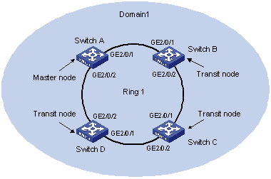
Figure 1-5 Network diagram for single ring topology
III. Configuration procedure
l Configure Switch A
<H3C> system-view
[H3C] rrpp domain 1
[H3C-rrpp-domain1] control-vlan 4092
[H3C-rrpp-domain1] ring 1 node-mode master primary-port GigabitEthernet2/0/1 secondary-port GigabitEthernet2/0/2 level 0
[H3C-rrpp-domain1] ring 1 enable
[H3C-rrpp-domain1] quit
[H3C] rrpp enable
l Configure Switch B
<H3C> system-view
[H3C] rrpp domain 1
[H3C-rrpp-domain1] control-vlan 4092
[H3C-rrpp-domain1] ring 1 node-mode transit primary-port GigabitEthernet2/0/1 secondary-port GigabitEthernet2/0/2 level 0
[H3C-rrpp-domain1] ring 1 enable
[H3C-rrpp-domain1] quit
[H3C] rrpp enable
l Configure Switch C
<H3C> system-view
[H3C] rrpp domain 1
[H3C-rrpp-domain1] control-vlan 4092
[H3C-rrpp-domain1] ring 1 node-mode transit primary-port GigabitEthernet2/0/1 secondary-port GigabitEthernet2/0/2 level 0
[H3C-rrpp-domain1] ring 1 enable
[H3C-rrpp-domain1] quit
[H3C] rrpp enable
l Configure Switch D
<H3C> system-view
[H3C] rrpp domain 1
[H3C-rrpp-domain1] control-vlan 4092
[H3C-rrpp-domain1] ring 1 node-mode transit primary-port GigabitEthernet2/0/1 secondary-port GigabitEthernet2/0/2 level 0
[H3C-rrpp-domain1] ring 1 enable
[H3C-rrpp-domain1] quit
[H3C] rrpp enable
After the configuration, you can use the display command to view the RRPP configuration and packet statistics.
1.6.2 Intersectant Ring Network Configuration Example
I. Network requirements
l Switch A, Switch B, Switch C, Switch D, and Switch E constitute RRPP domain 1.
l VLAN 4092 is the control VLAN of RRPP domain 1.
l Switch A, Switch B, Switch C, and Switch D constitute primary ring 1.
l Switch B, Switch C, and Switch E form subring 2.
l Switch A serves as the master node of the primary ring, GigabitEthernet 2/0/1 as the primary port, and GigabitEthernet 2/0/2 as the secondary port.
l Switch E serves as the master node of the subring, its GigabitEthernet 2/0/1 is the primary port, and its GigabitEthernet 2/0/2 is the secondary port.
l Switch B serves as a transit node of the primary ring and the edge node of the subring, its GigabitEthernet 2/0/2 is the common port, and its GigabitEthernet 2/0/3 is the edge port.
l Switch C serves as a transit node of the primary ring and an assistant edge node of the subring, its GigabitEthernet 2/0/1 is a common port, and its GigabitEthernet 2/0/3 is an edge port.
l Switch D serves as a transit node of the primary ring, its GigabitEthernet 2/0/1 is the primary port, and its GigabitEthernet 2/0/2 is the secondary port.
l The default values are used for the timer on the primary ring and the subring.
II. Network diagram
Figure 1-6 Network diagram for intersectant ring topology
III. Configuration procedure
l Configure Switch A
<H3C> system-view
[H3C] rrpp domain 1
[H3C-rrpp-domain1] control-vlan 4092
[H3C-rrpp-domain1] ring 1 node-mode master primary-port GigabitEthernet2/0/1 secondary-port GigabitEthernet2/0/2 level 0
[H3C-rrpp-domain1] ring 1 enable
[H3C-rrpp-domain1] quit
[H3C] rrpp enable
l Configure Switch B
<H3C> system-view
[H3C] rrpp domain 1
[H3C-rrpp-domain1] control-vlan 4092
[H3C-rrpp-domain1] ring 1 node-mode transit primary-port GigabitEthernet2/0/1 secondary-port GigabitEthernet2/0/2 level 0
[H3C-rrpp-domain1] ring 2 node-mode edge common-port GigabitEthernet 2/0/2 edge-port GigabitEthernet 2/0/3
[H3C-rrpp-domain1] ring 1 enable
[H3C-rrpp-domain1] ring 2 enable
[H3C-rrpp-domain1] quit
[H3C] rrpp enable
l Configure Switch C
<H3C> system-view
[H3C] rrpp domain 1
[H3C-rrpp-domain1] control-vlan 4092
[H3C-rrpp-domain1] ring 1 node-mode transit primary-port GigabitEthernet2/0/1 secondary-port GigabitEthernet2/0/2 level 0
[H3C-rrpp-domain-1] ring 2 node-mode assistant-edge common-port GigabitEthernet 2/0/1 edge-port GigabitEthernet 2/0/3
[H3C-rrpp-domain1] ring 1 enable
[H3C-rrpp-domain1] ring 2 enable
[H3C-rrpp-domain1] quit
[H3C] rrpp enable
l Configure Switch D
<H3C> system-view
[H3C] rrpp domain 1
[H3C-rrpp-domain1] control-vlan 4092
[H3C-rrpp-domain1] ring 1 node-mode transit primary-port GigabitEthernet2/0/1 secondary-port GigabitEthernet2/0/2 level 0
[H3C-rrpp-domain1] ring 1 enable
[H3C-rrpp-domain1] quit
[H3C] rrpp enable
l Configure Switch E
<H3C> system-view
[H3C] rrpp domain 1
[H3C-rrpp-domain1] control-vlan 4092
[H3C-rrpp-domain1] ring 2 node-mode master primary-port GigabitEthernet2/0/1 secondary-port GigabitEthernet2/0/2 level 1
[H3C-rrpp-domain1] ring 2 enable
[H3C-rrpp-domain1] quit
[H3C] rrpp enable
After the configuration, you can use the display command to view the RRPP configuration and packet statistics.