- Table of Contents
-
- H3C S7500 Series Operation Manual(Release 3100 Series)-(V1.04)
- 00-1Cover
- 00-2Overview
- 01-CLI Configuration
- 02-Login Configuration
- 03-Configuration File Management Configuration
- 04-VLAN Configuration
- 05-Extended VLAN Application Configuration
- 06-IP Address-IP Performance-IPX Configuration
- 07-GVRP Configuration
- 08-QinQ Configuration
- 09-Port Basic Configuration
- 10-Link Aggregation Configuration
- 11-Port Isolation Configuration
- 12-Port Binding Configuration
- 13-DLDP Configuration
- 14-MAC Address Table Configuration
- 15-MSTP Configuration
- 16-Routing Protocol Configuration
- 17-Multicast Configuration
- 18-802.1x Configuration
- 19-AAA-RADIUS-HWTACACS-EAD Configuration
- 20-Traffic Accounting Configuration
- 21-VRRP-HA Configuration
- 22-ARP Configuration
- 23-DHCP Configuration
- 24-ACL Configuration
- 25-QoS Configuration
- 26-Mirroring Configuration
- 27-Cluster Configuration
- 28-PoE Configuration
- 29-UDP-Helper Configuration
- 30-SNMP-RMON Configuration
- 31-NTP Configuration
- 32-SSH Terminal Service Configuration
- 33-File System Management Configuration
- 34-FTP and TFTP Configuration
- 35-Information Center Configuration
- 36-DNS Configuration
- 37-System Maintenance and Debugging Configuration
- 38-HWPing Configuration
- 39-RRPP Configuration
- 40-NAT-Netstream-Policy Routing Configuration
- 41-Telnet Protection Configuration
- 42-Hardware-Dependent Software Configuration
- Related Documents
-
| Title | Size | Download |
|---|---|---|
| 15-MSTP Configuration | 664 KB |
1.1.2 Basic MSTP Terminologies
1.1.4 MSTP Implementation on Switches
1.2.1 Configuration Prerequisites
1.2.2 MST Region Configuration
1.2.3 Root Bridge/Secondary Root Bridge Configuration
1.2.4 Bridge Priority Configuration
1.2.5 MSTP Operation Mode Configuration
1.2.6 MST Region Maximum Hops Configuration
1.2.7 Network Diameter Configuration
1.2.8 MSTP Time-related Configuration
1.2.9 Timeout Time Factor Configuration
1.2.10 Maximum Transmitting Speed Configuration
1.2.11 Edge Port Configuration
1.2.12 Point-to-point Link-Related Configuration
1.3.1 Configuration Prerequisites
1.3.2 MST Region Configuration
1.3.3 MSTP Operation Mode Configuration
1.3.4 Timeout Time Factor Configuration
1.3.5 Maximum Transmitting Speed Configuration
1.3.8 Port Priority Configuration
1.3.9 Point-to-point Link-Related Configuration
1.4.1 Configuration Prerequisites
1.5 Guard Function Configuration
1.5.2 Configuration Prerequisites
1.5.3 BPDU Guard Configuration
1.5.4 Root Guard Configuration
1.5.5 Loop Guard Configuration
1.5.6 TC-BPDU Attack Guard Configuration
1.6 Digest Snooping Configuration
1.6.2 Digest Snooping Configuration
1.7 Rapid Transition Configuration
1.7.2 Rapid Transition Configuration
1.8 VLAN-VPN Tunnel Configuration
1.8.2 VLAN-VPN Tunnel Configuration
1.9 Displaying and Debugging MSTP
1.10 MSTP Configuration Example
1.11 VLAN-VPN Tunnel Configuration Example
Chapter 1 MSTP Configuration
When configuring MSTP, go to these sections for information you are interested in:
l Guard Function Configuration
l Digest Snooping Configuration
l Rapid Transition Configuration
l VLAN-VPN Tunnel Configuration
l Displaying and Debugging MSTP
l VLAN-VPN Tunnel Configuration Example
1.1 MSTP Overview
Spanning tree protocol (STP) cannot enable Ethernet ports to transit their states rapidly. It costs two times of the forward delay for a port to transit to the forwarding state even if the port is on a point-to-point link or the port is an edge port. This slows down the spanning tree convergence of STP.
Rapid spanning tree protocol (RSTP) enables the spanning tree to converge rapidly, but it suffers from the same drawback as that of STP: all bridges in a LAN share one spanning tree; packets of all VLANs are forwarded along the same spanning tree, and therefore redundant links cannot be blocked based on VLANs.
As well as the above two protocols, multiple spanning tree protocol (MSTP) can disbranch a loop network to form a tree-topological loop-free network to prevent packets from being duplicated and forwarded endlessly in the loop network. Besides this, MSTP can also provide multiple redundant paths for packet forwarding and implement VLAN-based load balancing.
MSTP is compatible with both STP and RSTP. It overcomes the drawbacks of STP and RSTP. It not only enables spanning trees to converge rapidly, but also enables packets of different VLANs to be forwarded along their respective paths to provide a better load-balancing mechanism with redundant links.
1.1.1 MSTP Protocol Data Unit
Bridge protocol data unit (BPDU) is the protocol data unit (PDU) that STP and RSTP use.
The switches in a network transfer BPDUs between each other to determine the topology of the network. BPDUs carry enough information needed for switches to figure out the spanning tree.
BPDUs used in STP fall into the following two categories:
l Configuration BPDUs: BPDUs of this type are used to maintain the spanning tree topology.
l Topology change notification BPDU (TCN BPDU): BPDUs of this type are used to notify the switches of network changes.
Similar to STP and RSTP, MSTP uses BPDUs to figure out spanning trees too. Besides, the BPDUs of MSTP carry MSTP configuration information of the switches.
1.1.2 Basic MSTP Terminologies
Figure 1-1 illustrates basic MSTP terms (assuming that MSTP is enabled on each switch in this figure).

Figure 1-1 Basic MSTP terminologies
I. MST region
An MST region (multiple spanning tree region) comprises multiple physically-interconnected MSTP-enabled switches and the corresponding network segments connected to these switches. These switches have the same region name, the same VLAN-to-MSTI mapping table and the same MSTP revision level.
A switched network can contain multiple MST regions. You can group multiple switches into one MST region by using the corresponding MSTP configuration commands. For example, all switches in region A0 shown in Figure 1-1 have the same MST region configuration: the same region name, the same VLAN-to-MSTI mappings (that is, VLAN 1 is mapped to MSTI 1, VLAN 2 is mapped to MSTI 2, and other VLANs are mapped to CIST), the same MSTP revision level (not shown in Figure 1-1).
II. MSTI
A multiple spanning tree instance (MSTI) refers to a spanning tree in an MST region.
Multiple spanning trees can be established in one MST region. These MSTIs are independent of each other. For example, each region in Figure 1-1 contains multiple spanning trees known as MSTIs. Each of these spanning trees corresponds to the specific VLANs.
III. VLAN mapping table
A VLAN mapping table is a property of an MST region. It contains information about how VLANs are mapped to MSTIs. For example, in Figure 1-1, the information contained in the VLAN mapping table of region A0 is: VLAN 1 is mapped to MSTI 1; VLAN 2 is mapped to MSTI 2; and other VLANs are mapped to CIST. In an MST region, load balancing is achieved by the VLAN mapping table.
IV. IST
An internal spanning tree (IST) is a spanning tree in an MST region.
ISTs together with the common spanning tree (CST) form the common and internal spanning tree (CIST) of the entire switched network. An IST is a special MSTI; it belongs to an MST region and is a segment of the CIST. In Figure 1-1, each MST region has an IST, which is a segment of the CIST.
V. CST
A CST is the spanning tree in a switched network that connects all MST regions in the network. If you regard each MST region in the network as a switch, then the CST is the spanning tree generated by STP or RSTP running on the "switches". In Figure 1-1, the lines in red depict the CST.
VI. CIST
A CIST is the spanning tree in a switched network that connects all switches in the network. It comprises the ISTs and the CST. In Figure 1-1, the ISTs in the MST regions and the CST connecting the MST regions form the CIST.
VII. Region root
A region root is the root of the IST or an MSTI in an MST region. Different MSTIs in an MST region may have different topologies and thus have different region roots. In region D0 shown in Figure 1-1, the region root of MSTI 1 is switch B, and the region root of MSTI 2 is switch C.
VIII. Common root bridge
The common root bridge is the root of the CIST. The common root bridge of the network shown in Figure 1-1 is a switch in region A0.
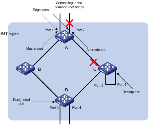
IX. Port roles
In MSTP, the following port roles exist: root port, designated port, master port, region edge port, alternate port, and backup port.
l A root port is used to forward packets to the root.
l A designated port is used to forward packets to a downstream network segment or switch.
l A master port connects an MST region to the common root. The path from the master port to the common root is the shortest path between the MST region and the common root.
l A region edge port is located on the edge of an MST region and is used to connect the MST region to another MST region, an STP-enabled region or an RSTP-enabled region
l An alternate port is a backup port of a master port. It becomes the master port if the existing master port is blocked.
l A loop occurs when two ports of a switch are connected to each other. In this case, the switch blocks one of the two ports. The blocked port is a backup port.
In Figure 1-2, switch A, B, C, and D form an MST region. Port 1 and port 2 on switch A connect upstream to the common root. Port 5 and port 6 on switch C form a loop. Port 3 and port 4 on switch D connect downstream to other MST regions. This figure shows the roles these ports play.
& Note:
l A port can play different roles in different MSTIs.
l The role a region edge port plays is consistent with the role it plays in the CIST. For example, port 1 on switch A in Figure 1-2 is a region edge port, and it is a master port in the CIST. So it is a master port in all MSTIs in the region.
X. Port states
Ports can be in the following three states:
l Forwarding state: Ports in this state can forward user packets and receive/send BPDU packets.
l Learning state: Ports in this state can receive/send BPDU packets.
l Discarding state: Ports in this state can only receive BPDU packets.
Table 1-1 lists possible combinations of port states and port roles.
Table 1-1 Combinations of port states and port roles
|
Port role Port state |
Root/ port/Master port |
Designated port |
Region edge port |
Alternate port |
Backup port |
|
Forwarding |
√ |
√ |
√ |
— |
— |
|
Learning |
√ |
√ |
√ |
— |
— |
|
Discarding |
√ |
√ |
√ |
√ |
√ |
1.1.3 Implementation of MSTP
MSTP divides a network into multiple MST regions at Layer 2. The CST is generated between these MST regions, and MSTIs can be generated in each MST region. As well as RSTP, MSTP uses configuration BPDUs to generate spanning trees. The only difference is that the configuration BPDUs for MSTP carry the MSTP configuration information on the switches.
I. Generating the CIST
Through configuration BPDU comparing, the switch that is of the highest priority in the network is chosen as the root of the CIST. In each MST region, an IST is generated by MSTP. At the same time, MSTP regards each MST region as a switch to figure out the CST of the network. The CST, together with the ISTs, forms the CIST of the network.
II. Generating an MSTI
In an MST region, different MSTIs are generated for different VLANs depending on the VLAN-to-MSTI mappings. Each MSTI is figured out independently, in the same way as STP/RSTP.
III. Implementation of STP algorithm
In the beginning, each switch regards itself as the root, and generates a configuration BPDU for each port on it as a root, with the root path cost being 0, the ID of the designated bridge being that of the switch, and the designated port being itself.
1) Each switch sends out its configuration BPDUs and operates in the following way when receiving a configuration BPDU on one of its ports from another switch:
l If the priority of the configuration BPDU is lower than that of the configuration BPDU of the port itself, the switch discards the BPDU and does not change the configuration BPDU of the port.
l If the priority of the configuration BPDU is higher than that of the configuration BPDU of the port itself, the switch replaces the configuration BPDU of the port with the received one and compares it with those of other ports on the switch to obtain the one with the highest priority.
2) Configuration BPDUs are compared as follows:
l The smaller the root ID of the configuration BPDU is, the higher the priority of the configuration BPDU is.
l For configuration BPDUs with the same root IDs, the comparison is based on the path costs. Suppose S is the sum of the root path cost and the corresponding path cost of the port. The less the S value is, the higher the priority of the configuration BPDU is.
l For configuration BPDUs with both the same root ID and the same root path cost, the designated bridge ID, designated port ID, the ID of the receiving port are compared in turn.
3) A spanning tree is figured out as follows:
l Determining the root bridge
The root bridge is selected by configuration BPDU comparing. The switch with the smallest root ID is selected as the root bridge.
l Determining the root port
For each switch in a network, the port through which the configuration BPDU with the highest priority is received is chosen as the root port of the switch.
l Determining the designated port
First, the switch generates a designated port configuration BPDU for each of its ports using the root port configuration BPDU and the root port path cost, with the root ID being replaced with that of the root port configuration BPDU, root path cost being replaced with the sum of the path cost of the root port configuration BPDU and the path cost of the root port, the ID of the designated bridge being replaced with that of the switch, and the ID of the designated port being replaced with that of the port.
The switch then compares the resulting configuration BPDU with the original configuration BPDU received from the corresponding port on another switch. If the latter takes precedence over the former, the switch blocks the local port and remains the port's configuration BPDU unchanged, so that the port can only receive configuration messages and cannot forward packets. Otherwise, the switch sets the local port to the designated port, replaces the original configuration BPDU of the port with the resulting one and releases it regularly.
1.1.4 MSTP Implementation on Switches
MSTP is compatible with both STP and RSTP. That is, switches with MSTP employed can recognize the protocol packets of STP and RSTP and use them to generate spanning trees. In addition to the basic MSTP functions, H3C series switches also provide the following other functions for the convenience of users to manage their switches.
l Root bridge retaining
l Root bridge backup
l Root guard
l BPDU guard
l Loop guard
1.2 Root Bridge Configuration
Complete the following tasks to configure Root Bridge:
|
Task |
Remarks |
|
Required To prevent network topology jitter caused by other related configurations, you are recommended to enable MSTP after other related configurations are performed. |
|
|
Required |
|
|
Required |
|
|
Optional The priority of a switch cannot be changed after the switch is specified as the root bridge or a secondary root bridge. |
|
|
Optional |
|
|
Optional |
|
|
Optional The default is recommended. |
|
|
Optional The defaults are recommended. |
|
|
Optional |
|
|
Optional The default is recommended. |
|
|
Optional |
|
|
Optional |
& Note:
In a network that contains switches with both GARP VLAN registration protocol (GVRP) and MSTP employed, GVRP packets are forwarded along the CIST. If you want to broadcast packets of a specific VLAN through GVRP, be sure to map the VLAN to the CIST when configuring the MSTP VLAN mapping table (The CIST of a network is the MSTI numbered 0.)
1.2.1 Configuration Prerequisites
The status of the switches in the spanning trees are determined. That is, the status (root, branch, or leaf) of each switch in each MSTI is determined.
1.2.2 MST Region Configuration
I. Configuration procedure
Follow these steps to configure an MST region:
|
To do … |
Use the command … |
Remarks |
|
Enter system view |
system-view |
— |
|
Enter MST region view |
stp region-configuration |
— |
|
Configure a name for the MST region |
region-name name |
Required The default MST region name of a switch is its MAC address. |
|
Configure the VLAN mapping table for the MST region |
instance instance-id vlan vlan-list |
Required Both commands can be used to configure VLAN mapping tables. By default, all VLANs in an MST region are mapped to MSTI 0. |
|
vlan-mapping modulo modulo |
||
|
Configure the MSTP revision level for the MST region |
revision-level level |
Required The default revision level of an MST region is level 0. |
|
Activate the configuration of the MST region manually |
active region-configuration |
Required |
|
Display the configuration of the current MST region |
check region-configuration |
Optional |
|
Display the currently valid configuration of the MST region |
display stp region-configuration |
You can execute this command in any view. |
Configuring MST region-related parameters (especially the VLAN mapping table) results in spanning trees being regenerated. To reduce network topology jitter caused by the configuration, MSTP does not regenerate spanning trees immediately after the configuration; it does this only after you perform one of the following operations, and then the configuration can really take effect:
l Activating the new MST region-related settings by using the active region-configuration command
l Enabling MSTP by using the stp enable command
& Note:
Switches belong to the same MST region only when they have the same MST region name, VLAN mapping table, and MSTP revision level.
II. Configuration example
# Configure an MST region, with the name being “info”, the MSTP revision level being level 1, VLAN 2 through VLAN 10 being mapped to MSTI 1, and VLAN 20 through VLAN 30 being mapped to MSTI 2.
<H3C> system-view
[H3C] stp region-configuration
[H3C-mst-region] region-name info
[H3C-mst-region] instance 1 vlan 2 to 10
[H3C-mst-region] instance 2 vlan 20 to 30
[H3C-mst-region] revision-level 1
[H3C-mst-region] active region-configuration
# Verify the above configuration.
[H3C-mst-region] check region-configuration
Admin configuration
Format selector :0
Region name :info
Revision level :1
Instance Vlans Mapped
0 1, 11 to 19, 31 to 4094
1 2 to 10
2 20 to 30
1.2.3 Root Bridge/Secondary Root Bridge Configuration
I. Root bridge configuration
Follow these steps to specify the current switch as the root bridge of a specified MSTI:
|
To do ... |
Use the command ... |
Remarks |
|
Enter system view |
system-view |
— |
|
Specify the current switch as the root bridge of a specified MSTI |
stp [ instance instance-id ] root primary [ bridge-diameter bridgenumber ] [ hello-time centi-seconds ] |
Required |
II. Secondary root bridge configuration
Follow these steps to specify the current switch as the secondary root bridge of a specified MSTI:
|
To do ... |
Use the command ... |
Remarks |
|
Enter system view |
system-view |
— |
|
Specify the current switch as the secondary root bridge of a specified MSTI |
stp [ instance instance-id ] root secondary [ bridge-diameter bridgenumber ] [ hello-time centi-seconds ] |
Required |
Use the stp root primary/stp root secondary command to specify a switch as the root bridge or the secondary root bridge of the MSTI identified by the instance-id argument. If the value of the instance-id argument is set to 0, the stp root primary/stp root secondary command specify the current switch as the root bridge or the secondary root bridge of the CIST.
A switch can play different roles in different MSTIs. That is, it can be the root bridges in a MSTI and be a secondary root bridge in another MSTI at the same time. But in one MSTI, a switch cannot be the root bridge and the secondary root bridge simultaneously.
When the root bridge fails or is turned off, the secondary root bridge becomes the root bridge if no new root bridge is configured. If you configure multiple secondary root bridges for a MSTI, the one with the least MAC address replaces the root bridge when the latter fails.
You can specify the network diameter and the Hello time parameters while configuring a root bridge/secondary root bridge. Refer to section 1.2.7 “Network Diameter Configuration” and 1.2.8 “MSTP Time-related Configuration” for information about the network diameter parameter and the Hello time parameter.
& Note:
l You can configure a switch as the root bridge of multiple MSTIs. But you cannot configure two or more root bridges for one MSTI. So, do not configure root bridge for the same MSTI on two or more switches using the stp root primary command.
l You can configure multiple secondary root bridges for one MSTI. That is, you can configure secondary root bridges for the same MSTI on two or more switches using the stp root secondary command.
l You can also configure the current switch as the root bridge by setting the priority of the switch to 0. Note that once a switch is configured as the root bridge or a secondary root bridge, its priority cannot be modified.
III. Configuration example
# Configure the current switch as the root bridge of MSTI 1 and a secondary root bridge of MSTI 2.
<H3C> system-view
[H3C] stp instance 1 root primary
[H3C] stp instance 2 root secondary
1.2.4 Bridge Priority Configuration
Root bridges are selected by the bridge priorities of switches. You can make a specific switch be selected as a root bridge by setting a higher bridge priority for the switch (Note that a smaller bridge priority value indicates a higher bridge priority.) An MSTP-enabled switch can have different bridge priorities in different MSTIs.
I. Configuration procedure
Follow these steps to assign a bridge priority to a switch:
|
To do ... |
Use the command ... |
Remarks |
|
Enter system view |
system-view |
— |
|
Set a bridge priority for the current switch |
stp [ instance instance-id ] priority priority |
Required The default bridge priority of a switch is 32,768. |
![]() Caution:
Caution:
l Once you specify a switch as the root bridge or a secondary root bridge by using the stp root primary or stp root secondary command, the bridge priority of the switch is not configurable.
l During the selection of the root bridge, if multiple switches have the same bridge priority, the one with the least MAC address becomes the root bridge.
II. Configuration example
# Set the bridge priority of the current switch to 4,096 in MSTI 1.
<H3C> system-view
[H3C] stp instance 1 priority 4096
1.2.5 MSTP Operation Mode Configuration
An MSTP-enabled switch can operate in one of the following operation modes:
l STP-compatible mode: In this mode, the protocol packets sent out of the ports of the switch are STP packets. If the switched network contains STP-enabled switches, you can configure the current MSTP-enabled switch to operate in this mode by using the stp mode stp command.
l RSTP-compatible mode: In this mode, the protocol packets sent out of the ports of the switch are RSTP packets. If the switched network contains RSTP-enabled switches, you can configure the current MSTP-enabled switch to operate in this mode by using the stp mode rstp command.
l MSTP mode: In this mode, the protocol packets sent out of the ports of the switch are MSTP packets, or STP packets if the ports have STP-enabled switches connected. But the multiple spanning tree function is only enabled for MSTP packets.
I. Configuration procedure
Follow these steps to configure MSTP operation mode:
|
To do ... |
Use the command ... |
Remarks |
|
Enter system view |
system-view |
— |
|
Configure the MSTP operation mode for the switch |
stp mode { stp | rstp | mstp } |
Required An MSTP-enabled switch operates in the MSTP mode by default. |
II. Configuration example
# Configure the current switch to operate in the STP-compatible mode.
<H3C> system-view
[H3C] stp mode stp
1.2.6 MST Region Maximum Hops Configuration
The maximum hop values configured on the region roots in an MST region limit the size of the MST region.
A configuration BPDU contains a field that maintains the remaining hops of the configuration BPDU. And a switch discards the configuration BPDUs whose remaining hops are 0. After a configuration BPDU reaches a root bridge of an MSTI in an MST region, the value of the remaining hops field in the configuration BPDU is decreased by 1 every time the configuration BPDU passes a switch. Such a mechanism disables the switches beyond the maximum hops from participating in spanning tree generation, and thus limits the size of an MST region.
With such a mechanism, the maximum hops configured on the switch operating as the root bridge of the CIST or an MSTI in an MST region becomes the network diameter of the spanning tree, which limits the size of the spanning tree in the current MST region. The switches that are not root bridges in the MST region adopt the maximum hops settings of their root bridges.
I. Configuration procedure
Follow these steps to configure the maximum hops for an MST region:
|
To do ... |
Use the command ... |
Remarks |
|
Enter system view |
system-view |
— |
|
Configure the maximum hops for the MST region |
stp max-hops hops |
Required By default, the maximum hops of an MST region are 20. |
Note that only the maximum hops settings on the switches operating as region roots can limit the size of the MST region.
II. Configuration example
# Configure the maximum hops of the MST region to be 30 (assuming that the current switch operates as the region root).
<H3C> system-view
[H3C] stp max-hops 30
1.2.7 Network Diameter Configuration
In a switched network, any two switches can communicate with each other through a path, on which there may be some other switches. The network diameter of a network is measured by the number of switches; it equals the number of the switches on the longest path (that is, the path containing the maximum number of switches).
I. Configuration procedure
Follow these steps to configure the network diameter for a network:
|
To do ... |
Use the command ... |
Remarks |
|
Enter system view |
system-view |
— |
|
Configure the network diameter for a network |
stp bridge-diameter bridgenumber |
Required The default network diameter of a network is 7. |
The network diameter parameter indicates the size of a network. The larger the network diameter is, the larger the network size is.
After you configure the network diameter of a switched network, an MSTP-enabled switch adjusts its Hello time, Forward delay, and Max age settings accordingly.
The network diameter setting only applies to the CIST and it is invalid for MSTIs.
II. Configuration example
# Configure the network diameter of the switched network to 6.
<H3C> system-view
[H3C] stp bridge-diameter 6
1.2.8 MSTP Time-related Configuration
l The Forward delay parameter sets the delay of state transition.
Link failures in a network result in the spanning trees being regenerated and original spanning tree structures being changed. As the newly generated configuration BPDUs cannot be propagated across the entire network immediately when the new spanning trees are generated, loops may occur if the new root ports and designated ports begin to forward packets immediately.
This problem can be avoided by adopting a state transition mechanism. With this mechanism, newly selected root ports and designated ports undergo an intermediate state before they begin to forward packets. That is, it costs these ports a period (specified by the Forward delay parameter) for them to turn to the forwarding state. The period ensures that the newly generated configuration BPDUs can be propagated across the entire network.
l The Hello time parameter is for link failure detecting.
A switch regularly sends hello packets to other switches at the interval specified by the Hello time parameter to detect the link failures.
l The Max age parameter is used to judge whether or not a configuration BPDU is obsolete. Obsolete configuration BPDUs will be discarded.
I. Configuration procedure
Follow these steps to configure MSTP time-related parameters:
|
To do ... |
Use the command ... |
Remarks |
|
Enter system view |
system-view |
— |
|
Configure the Forward delay parameter |
stp timer forward-delay centiseconds |
Required The Forward delay parameter defaults to 1,500 centiseconds (15 seconds). |
|
Configure the Hello time parameter |
stp timer hello centiseconds |
Required The Hello time parameter defaults to 200 centiseconds (2 seconds). |
|
Configure the Max age parameter |
stp timer max-age centiseconds |
Required The Max age parameter defaults to 2,000 centiseconds (20 seconds). |
All switches in a switched network adopt the three time-related parameters configured on the CIST root bridge.
![]() Caution:
Caution:
l The Forward delay parameter and the network diameter are correlated. Normally, a large network diameter corresponds to a large Forward delay. A too small Forward delay parameter may result in temporary redundant paths. And a too large Forward delay parameter may cause a network unable to resume the normal state in time after changes occurred to the network. The default value is recommended.
l An adequate Hello time parameter enables a switch to be aware of link failures in time without occupying too much network resources. Too large a Hello time parameter may result in normal links being regarded as invalid when packets get lost on them, which in turn results in spanning trees being regenerated. And too small a Hello time parameter may result in duplicated configuration BPDUs being sent frequently, which increases the work load of the switches and wastes network resources. The default value is recommended.
l As for the Max age parameter, if it is too small, network congestions may be falsely regarded as link failures, which results in spanning trees being frequently regenerated. If it is too large, link failures may be unable to be detected in time, which in turn disables spanning trees being regenerated in time and makes the network less adaptive. The default value is recommended.
As for the configuration of these three time-related parameters (that is, the Hello time, Forward delay, and Max age parameters), the following formulas must be met to prevent network jitter.
2 x (Forward delay – 1 second) >= Max age
Max age >= 2 x (Hello time + 1 second)
You are recommended to specify the network diameter of the switched network and the Hello time by using the stp root primary or stp root secondary command. After that, the three proper time-related parameters are determined automatically.
II. Configuration example
# Configure the Forward delay parameter to be 1,600 centiseconds, the Hello time parameter to be 300 centiseconds, and the Max age parameter to be 2,100 centiseconds (assuming that the current switch operates as the CIST root bridge).
<H3C> system-view
[H3C] stp timer forward-delay 1600
[H3C] stp timer hello 300
[H3C] stp timer max-age 2100
1.2.9 Timeout Time Factor Configuration
A switch regularly sends protocol packets to its neighboring devices at the interval specified by the Hello time parameter to detect the link failures. Normally, a switch regards its upstream switch faulty if the former does not receive any protocol packets from the latter in a period three times of the Hello time and then initiates the spanning tree regeneration process.
Spanning trees may be regenerated even in a steady network if an upstream switch continues to be busy. You can configure the timeout time factor to a larger number to avoid this problem. Normally, the timeout time can be four or more times of the Hello time. For a steady network, the timeout time can be five to seven times of the Hello time.
I. Configuration procedure
Follow these steps to configure timeout time factor:
|
To do ... |
Use the command ... |
Remarks |
|
Enter system view |
system-view |
— |
|
Configure the timeout time factor for the switch |
stp timer-factor number |
Required The timeout time factor defaults to 3. |
Normally, you are recommended to set the timeout time factor to 5 through 7.
II. Configuration example
# Configure the timeout time factor to be 6.
<H3C> system-view
[H3C] stp timer-factor 6
1.2.10 Maximum Transmitting Speed Configuration
The maximum transmitting speed of a port specifies the maximum number of configuration BPDUs a port can transmit in a period specified by the Hello time parameter. It depends on the physical state of the port and network structure. You can configure this parameter according to the network.
I. Configuration procedure (in system view)
Follow these steps to configure the maximum transmitting speed for specified ports in system view:
|
To do ... |
Use the command ... |
Remarks |
|
Enter system view |
system-view |
— |
|
Configure the maximum transmitting speed for specified ports |
stp interface interface-list transmit-limit packetnum |
Required The maximum transmitting speed of all Ethernet ports on a switch defaults to 10. |
II. Configuration procedure (in Ethernet port view)
Follow these steps to configure the maximum transmitting speed in Ethernet port view:
|
To do ... |
Use the command ... |
Remarks |
|
Enter system view |
system-view |
— |
|
Enter Ethernet port view |
interface interface-type interface-number |
— |
|
Configure the maximum transmitting speed |
stp transmit-limit packetnum |
Required The maximum transmitting speed of all Ethernet ports on a switch defaults to 10. |
As the maximum transmitting speed parameter determines the number of the configuration BPDUs transmitted in each Hello time, set it to a proper value to avoid MSTP from occupying too many network resources. The default value is recommended.
III. Configuration example
# Set the maximum transmitting speed of Ethernet2/0/1 to 15.
1) Configure the maximum transmitting speed in system view.
<H3C> system-view
[H3C] stp interface ethernet2/0/1 transmit-limit 15
2) Configure the maximum transmitting speed in Ethernet port view.
<H3C> system-view
[H3C] interface ethernet2/0/1
[H3C-Ethernet2/0/1] stp transmit-limit 15
1.2.11 Edge Port Configuration
Edge ports are ports that neither directly connects to other switches nor indirectly connects to other switches through network segments. After a port is configured as an edge port, rapid transition is applicable to the port. That is, when the port changes from blocking state to forwarding state, it does not have to wait for any delay.
You can configure a port as an edge port in the following two ways.
I. Configuration procedure (in system view)
Follow these steps to configure a port as an edge port (in system view):
|
To do ... |
Use the command ... |
Remarks |
|
Enter system view |
system-view |
— |
|
Configure the specified ports as edge ports |
stp interface interface-list edged-port enable |
Required By default, all the Ethernet ports of a switch are non-edge ports. |
II. Configuration procedure (in Ethernet port view)
Follow these steps to configure a port as an edge port (in Ethernet port view):
|
To do ... |
Use the command ... |
Remarks |
|
Enter system view |
system-view |
— |
|
Enter Ethernet port view |
interface interface-type interface-number |
— |
|
Configure the port as an edge port |
stp edged-port enable |
Required By default, all the Ethernet ports of a switch are non-edge ports. |
On a switch with BPDU guard not enabled, an edge port becomes a non-edge port again once it receives a BPDU from another port.
& Note:
You are recommended to configure the Ethernet ports connected directly to terminals as edge ports and enable the BPDU guard function as well. This not only enables these ports to transit to forwarding state rapidly but also secures your network.
III. Configuration example
# Configure Ethernet2/0/1 as an edge port.
1) Configure in system view.
<H3C> system-view
[H3C] stp interface ethernet2/0/1 edged-port enable
2) Configure in Ethernet port view.
<H3C> system-view
[H3C] interface ethernet2/0/1
[H3C-Ethernet2/0/1] stp edged-port enable
1.2.12 Point-to-point Link-Related Configuration
You can specify whether or not the link connected to a port is a point-to-point link in one of the following two ways.
I. Configuration procedure (in system view)
Follow these steps to specify whether or not the links connected to the specified ports are point-to-point links (in system view):
|
To do ... |
Use the command ... |
Remarks |
|
Enter system view |
system-view |
— |
|
Specify whether or not the links connected to the specified ports are point-to-point links |
stp interface interface-list point-to-point { force-true | force-false | auto } |
Required The auto keyword is adopted by default. The force-true keyword specifies that the links connected to the specified ports are point-to-point links. The force-false keyword specifies that the links connected to the specified ports are not point-to-point links. The auto keyword specifies to automatically determine whether or not the links connected to the specified ports are point-to-point links. |
II. Configuration procedure (in Ethernet port view)
Follow these steps to specify whether or not the link connected to a specific port is a point-to-point link (in Ethernet port view):
|
To do ... |
Use the command ... |
Remarks |
|
Enter system view |
system-view |
— |
|
Enter Ethernet port view |
interface interface-type interface-number |
— |
|
Specify whether or not the link connected to the port is a point-to-point link |
stp point-to-point { force-true | force-false | auto } |
Required The auto keyword is adopted by default. The force-true keyword specifies that the link connected to the port is a point-to-point link. The force-false keyword specifies that the link connected to the port is not a point-to-point link. The auto keyword specifies to automatically determine whether or not the link connected to the port is a point-to-point link. |
& Note:
Among aggregated ports, you can configure only the links of master ports as point-to-point links. If an auto-negotiating port operates in full duplex mode after negotiation, you can configure the link of the port as a point-to-point link.
After you configure the link of a port as a point-to-point link, the configuration applies to all MSTIs. If the actual physical link of a port is not a point-to-point link and you forcibly configure the link as a point-to-point link, temporary loops may be incurred.
III. Configuration example
# Configure the link connected to Ethernet2/0/1 as a point-to-point link.
1) Configure in system view.
<H3C> system-view
[H3C] stp interface ethernet2/0/1 point-to-point force-true
2) Configure in Ethernet port view.
<H3C> system-view
[H3C] interface ethernet2/0/1
[H3C-Ethernet2/0/1] stp point-to-point force-true
1.2.13 MSTP Configuration
I. Configuration procedure
Follow these steps to enable/disable MSTP in system view:
|
To do ... |
Use the command ... |
Remarks |
|
Enter system view |
system-view |
— |
|
Enable MSTP |
stp enable |
Required MSTP is disabled by default. |
|
Disable MSTP on specified ports |
stp interface interface-list disable |
Optional By default, MSTP is enabled on all ports after you enable MSTP in system view. To enable a switch to operate more flexibly, you can disable MSTP on specific ports. As MSTP-disabled ports do not participate in spanning tree generation, this operation saves CPU resources. |
Follow these steps to disable/disable MSTP in Ethernet port view:
|
To do ... |
Use the command ... |
Remarks |
|
Enter system view |
system-view |
— |
|
Enable MSTP |
stp enable |
Required MSTP is disabled by default. |
|
Enter Ethernet port view |
Interface interface-type interface-number |
— |
|
Disable MSTP on the port |
stp disable |
Optional By default, MSTP is enabled on all ports after you enable MSTP in system view. To enable a switch to operate more flexibly, you can disable MSTP on specific ports. As MSTP-disabled ports do not participate in spanning tree generation, this operation saves CPU resources. |
Other MSTP-related settings can take effect only after MSTP is enabled on the switch.
II. Configuration example
# Enable MSTP on the switch and disable MSTP on Ethernet2/0/1.
1) Configure in system view.
<H3C> system-view
[H3C] stp enable
[H3C] stp interface ethernet2/0/1 disable
2) Configure in Ethernet port view.
<H3C> system-view
[H3C] stp enable
[H3C] interface ethernet2/0/1
[H3C-Ethernet2/0/1] stp disable
1.3 Leaf Node Configuration
Complete the following tasks to configure leaf node:
|
Task |
Remarks |
|
Required To prevent network topology jitter caused by other related configurations, you are recommended to enable MSTP after performing other configurations. |
|
|
Required |
|
|
Optional |
|
|
Optional |
|
|
Optional The default value is recommended. |
|
|
Optional |
|
|
Optional |
|
|
Optional |
|
|
Optional |
& Note:
In a network that contains switches with both GVRP and MSTP employed, GVRP packets are forwarded along the CIST. If you want to broadcast packets of a specific VLAN through GVRP, be sure to map the VLAN to the CIST when configuring the MSTP VLAN mapping table (the CIST of a network is the MSTI numbered 0.)
1.3.1 Configuration Prerequisites
The status of the switches in the spanning trees is determined. That is, the status (root, branch, or leaf) of each switch in each MSTI is determined.
1.3.2 MST Region Configuration
Refer to section MST Region Configuration.
1.3.3 MSTP Operation Mode Configuration
Refer to section MSTP Operation Mode Configuration.
1.3.4 Timeout Time Factor Configuration
Refer to section Timeout Time Factor Configuration.
1.3.5 Maximum Transmitting Speed Configuration
Refer to section Maximum Transmitting Speed Configuration.
1.3.6 Edge Port Configuration
Refer to section Edge Port Configuration.
1.3.7 Path Cost Configuration
The path cost parameters reflects the link rates on ports. For a port on an MSTP-enabled switch, the path cost may differ with MSTIs. You can enable flows of different VLANs to travel along different physical links by configuring appropriate path costs on ports, so that load balancing can be achieved by VLANs.
Path costs can be determined by switches or through manual configuration.
I. Standards for calculating path costs of ports
Currently, a switch can calculate the path costs of ports based on one of the following standards:
l dot1d-1998: Adopts the IEEE 802.1D-1998 standard to calculate the default path costs of ports.
l dot1t: Adopts the IEEE 802.1t standard to calculate the default path costs of ports.
l legacy: Adopts the standard defined by private to calculate the default path costs of ports.
Follow these steps to specify the standard for calculating path costs:
|
To do ... |
Use the command ... |
Remarks |
|
Enter system view |
system-view |
— |
|
Specify the standard to be used to calculate the default path costs of the links connected to the ports of the switch |
stp pathcost-standard { dot1d-1998 | dot1t | legacy } |
Optional By default, the legacy standard is used to calculate the default path costs. |
Table 1-2 Transmission speeds and the corresponding path costs
|
Transmission speed |
Operation mode (half-/full-duplex) |
802.1D-1998 |
IEEE 802.1t |
Proprietary standard |
|
0 |
— |
65,535 |
200,000,000 |
200,000 |
|
10 Mbps |
Half-duplex/Full-duplex Aggregated link 2 ports Aggregated link 3 ports Aggregated link 4 ports |
100 95 95 95 |
2,000,000 1,000,000 666,666 500,000 |
2,000 1,800 1,600 1,400 |
|
100 Mbps |
Half-duplex/Full-duplex Aggregated link 2 ports Aggregated link 3 ports Aggregated link 4 ports |
19 15 15 15 |
200,000 100,000 66,666 50,000 |
200 180 160 140 |
|
1,000 Mbps |
Full-duplex Aggregated link 2 ports Aggregated link 3 ports Aggregated link 4 ports |
4 3 3 3 |
20,000 10,000 6,666 5,000 |
20 18 16 14 |
|
10 Gbps |
Full-duplex Aggregated link 2 ports Aggregated link 3 ports Aggregated link 4 ports |
2 1 1 1 |
2,000 1,000 666 500 |
2 1 1 1 |
Normally, the path cost of a port operating in full-duplex mode is slightly less than that of the port operating in half-duplex mode.
When calculating the path cost of an aggregated link, the 802.1D-1998 standard does not take the number of the ports on the aggregated link into account, whereas the 802.1T standard does. The following formula is used to calculate the path cost of an aggregated link:
Path cost = 200,000,000/ link transmission speed (in 100 kbps),
Where the link transmission speed is the sum of the speeds of the unblocked ports on the aggregated link, which is measured in 100 Kbps.
II. Configuring the path costs of ports
Follow these steps to configure the path cost for specified ports in system view:
|
To do ... |
Use the command ... |
Remarks |
|
Enter system view |
system-view |
— |
|
Configure the path cost for specified ports |
stp interface interface-list [ instance instance-id ] cost cost |
Required An MSTP-enabled switch can calculate path costs for all its ports automatically. |
Follow these steps to configure the path cost for a port in Ethernet port view:
|
To do ... |
Use the command ... |
Remarks |
|
Enter system view |
system-view |
— |
|
Enter Ethernet port view |
interface interface-type interface-number |
— |
|
Configure the path cost for the port |
stp [ instance instance-id ] cost cost |
Required An MSTP-enabled switch can calculate path costs for all its ports automatically. |
Changing the path cost of a port may change the role of the port and put it in state transition. Executing the stp cost command with the instance-id argument being 0 sets the path cost on the CIST for the port.
III. Configuration example (A)
# Configure the path cost of Ethernet2/0/1 in MSTI 1 to be 2,000.
1) Configure in system view.
<H3C> system-view
[H3C] stp interface ethernet2/0/1 instance 1 cost 2000
2) Configure in Ethernet port view.
<H3C> system-view
[H3C] interface ethernet2/0/1
[H3C-Ethernet2/0/1] stp instance 1 cost 2000
IV. Configuration example (B)
# Change the path cost of Ethernet2/0/1 in MSTI 1 to the default one calculated with the IEEE 802.1D-1998 standard.
1) Configure in system view.
<H3C> system-view
[H3C] stp pathcost-standard dot1d-1998
2) Configure in Ethernet port view.
<H3C> system-view
[H3C] interface ethernet2/0/1
[H3C-Ethernet2/0/1] quit
[H3C] stp pathcost-standard dot1d-1998
1.3.8 Port Priority Configuration
Port priority is an important criterion on determining the root port. In the same condition, ports with smaller port priority values are more potential to become the root port than those with bigger priority values.
A port on an MSTP-enabled switch can have different port priorities and play different roles in different MSTIs. This enables packets of different VLANs to be forwarded along different physical paths, so that load balancing can be achieved based on VLANs.
You can configure port priority in the following two ways.
I. Configuring port priority in system view
Follow these steps to configure port priority for specified ports in system view:
|
To do ... |
Use the command ... |
Remarks |
|
Enter system view |
system-view |
— |
|
Configure port priority for specified ports |
stp interface interface-list instance instance-id port priority priority |
Required The default port priority is 128. |
II. Configuring port priority in Ethernet port view
Follow these steps to configure port priority for a specified port in Ethernet port view:
|
To do ... |
Use the command ... |
Remarks |
|
Enter system view |
system-view |
— |
|
Enter Ethernet port view |
interface interface-type interface-number |
— |
|
Configure port priority for the port |
stp [ instance instance-id ] port priority priority |
Required. The default port priority is 128. |
Changing port priority of a port may change the role of the port and put the port into state transition.
A smaller port priority value indicates a higher possibility for the port to become the root port. If all the ports of a switch have the same port priority value, the port priorities are determined by the port indexes. Changing the priority of a port will cause spanning tree regeneration.
You can configure port priorities according to actual networking requirements.
III. Configuration example
# Configure the port priority of Ethernet2/0/1 in MSTI 1 to be 16.
1) Configure in system view.
<H3C> system-view
[H3C] stp interface ethernet2/0/1 instance 1 port priority 16
2) Configure in Ethernet port view.
<H3C> system-view
[H3C] interface ethernet2/0/1
[H3C-Ethernet2/0/1] stp instance 1 port priority 16
1.3.9 Point-to-point Link-Related Configuration
Refer to section 1.2.12 “Point-to-point Link-Related Configuration”.
1.3.10 MSTP Configuration
Refer to section 1.2.13 “MSTP Configuration”.
1.4 The mCheck Configuration
As mentioned previously, ports on an MSTP-enabled switch can operate in three modes: STP-compatible, RSTP-compatible, and MSTP.
A port on an MSTP-enabled switch operating as an upstream switch transits to the STP-compatible mode when it has an STP-enabled switch connected to it. When the STP enabled downstream switch is then replaced by an MSTP-enabled switch, the port cannot automatically transit to the MSTP mode. It remains in the STP-compatible mode. In this case, you can force the port to transit to the MSTP mode by performing the mCheck operation on the port.
1.4.1 Configuration Prerequisites
MSTP runs normally on the switch.
1.4.2 Configuration Procedure
You can perform the mCheck operation in the following two ways.
I. Performing the mCheck operation in system view
Follow these steps to perform the mCheck operation in system view:
|
To do ... |
Use the command ... |
Remarks |
|
Enter system view |
system-view |
— |
|
Perform the mCheck operation |
stp [ interface interface-list ] mcheck |
Required |
II. Performing the mCheck operation in Ethernet port view
Follow these steps to perform the mCheck operation in Ethernet port view:
|
To do ... |
Use the command ... |
Remarks |
|
Enter system view |
system-view |
— |
|
Enter Ethernet port view |
interface interface-type interface-number |
— |
|
Perform the mCheck operation |
stp mcheck |
Required |
1.4.3 Configuration Example
# Perform the mCheck operation on Ethernet2/0/1.
1) Configure in system view.
<H3C> system-view
[H3C] stp interface ethernet2/0/1 mcheck
2) Configure in Ethernet port view.
<H3C> system-view
[H3C] interface ethernet2/0/1
[H3C-Ethernet2/0/1] stp mcheck
1.5 Guard Function Configuration
1.5.1 Introduction
The following guard functions are available on an MSTP-enabled switch: BPDU guard, root guard, loop guard, and TC-BPDU attack guard.
I. BPDU guard
Normally, the access ports of the devices operating on the access layer directly connect to terminals (such as PCs) or file servers. These ports are usually configured as edge ports to achieve rapid transition. But they resume non-edge ports automatically upon receiving configuration BPDUs, which causes spanning tree regeneration and network topology jitter.
Normally, no configuration BPDU will reach edge ports. But malicious users can attack a network by sending configuration BPDUs deliberately to edge ports to cause network jitter. You can prevent this type of attacks by utilizing the BPDU guard function. With this function enabled on a switch, the switch shuts down the edge ports that receive configuration BPDUs and then reports these cases to the administrator. If a port is shut down, only the administrator can restore it.
II. Root guard
A root bridge and its secondary root bridges must reside in the same region. A CIST and its secondary root bridges are usually located in the high-bandwidth core region. Configuration errors or attacks may result in configuration BPDUs with their priorities higher than that of a root bridge, which causes a new root bridge to be elected and network topology jitter to occur. In this case, flows that should travel along high-speed links may be led to low-speed links, and network congestion may occur.
You can avoid this problem by utilizing the root guard function. Ports with this function enabled can only be kept as designated ports in all MSTIs. When a port of this type receives configuration BPDUs with higher priorities, it changes to discarding state (rather than becomes a non-designated port) and stops forwarding packets (as if it is disconnected from the link). It resumes the normal state if it does not receive any configuration BPDUs with higher priorities for a specified period.
III. Loop guard
A switch maintains the states of the root port and other blocked ports by receiving and processing BPDUs from the upstream switch. These BPDUs may get lost because of network congestions and link failures. If a switch does not receive BPDUs from the upstream switch for a certain period, the switch selects a new root port; the original root port becomes a designated port; and the blocked ports transit to forwarding state. This may cause loops in the network.
The loop guard function suppresses loops. With this function enabled, if link congestions or uni-directional link failures occur, both the root port and the blocked ports become designated ports and change to discarding state. In this case, they stop forwarding packets, and thereby loops can be prevented.
IV. TC-BPDU attack guard
A switch removes MAC address entries and ARP entries upon receiving TC-BPDUs. If a malicious user sends a large amount of TC-BPDUs to a switch in a short period, the switch may busy itself in removing MAC address entries and ARP entries, which may decreases the performance and stability of the switch.
With the TC-BPDU guard function enabled, the switch performs only one removing operation in a specified period ( 10 seconds by default) after it receives a TC-BPDU. The switch also checks to see if other TC-BPDUs arrive in this period and performs another removing operation in the next period if a TC-BPDU is received. Such a mechanism prevents a switch from busying itself in performing removing operations.
![]() Caution:
Caution:
Among loop guard function, root guard function, and edge port setting, only one can be valid on a port at one time.
1.5.2 Configuration Prerequisites
MSTP runs normally on the switch.
1.5.3 BPDU Guard Configuration
I. Configuration procedure
Follow these steps to enable the BPDU guard function:
|
To do ... |
Use the command ... |
Remarks |
|
Enter system view |
system-view |
— |
|
Enable the BPDU guard function |
stp bpdu-protection |
Required The BPDU guard function is disabled by default. |
II. Configuration example
# Enable the BPDU guard function.
<H3C> system-view
[H3C] stp bpdu-protection
1.5.4 Root Guard Configuration
I. Configuration procedure
Follow these steps to enable the root guard function in system view:
|
To do ... |
Use the command ... |
Remarks |
|
Enter system view |
system-view |
— |
|
Enable the root guard function on specified ports |
stp interface interface-list root-protection |
Required The root guard function is disabled by default. |
Follow these steps to enable the root guard function in Ethernet port view:
|
To do ... |
Use the command ... |
Remarks |
|
Enter system view |
system-view |
— |
|
Enter Ethernet port view |
Interface interface-type interface-number |
— |
|
Enable the root guard function on current port |
stp root-protection |
Required The root guard function is disabled by default. |
II. Configuration example
# Enable the root guard function on Ethernet2/0/1.
1) Configure in system view.
<H3C> system-view
[H3C] stp interface ethernet2/0/1 root-protection
2) Configure in Ethernet port view.
<H3C> system-view
[H3C] interface ethernet2/0/1
[H3C-Ethernet2/0/1] stp root-protection
1.5.5 Loop Guard Configuration
I. Configuration procedure
Follow these steps to enable the loop guard function on a port:
|
To do ... |
Use the command ... |
Remarks |
|
Enter system view |
system-view |
— |
|
Enter Ethernet port view |
interface interface-type interface-number |
— |
|
Enable the loop guard function on the current port |
stp loop-protection |
Required The loop guard function is disabled by default. |
II. Configuration example
# Enable loop guard function on Ethernet2/0/1.
<H3C> system-view
[H3C] interface ethernet2/0/1
[H3C-Ethernet2/0/1] stp loop-protection
1.5.6 TC-BPDU Attack Guard Configuration
I. Configuration procedure
Follow these steps to enable the TC-BPDU attack guard function:
|
To do ... |
Use the command ... |
Remarks |
|
Enter system view |
system-view |
— |
|
Enable the TC-BPDU attack guard function |
stp tc-protection enable |
Required The TC-BPDU attack guard function is disabled by default. |
II. Configuration example
# Enable the TC-BPDU attack guard function.
<H3C> system-view
[H3C] stp tc-protection enable
1.6 Digest Snooping Configuration
1.6.1 Introduction
According to IEEE 802.1s, two interconnected MSTP switches can interwork with each other through MSTIs in an MST region only when the two switches have the same MST region-related configuration. Interconnected MSTP switches determine whether or not they are in the same MST region by checking the configuration IDs of the BPDUs between them. (A configuration ID contains information such as region ID and configuration digest.)
As some other vendors' switches adopt proprietary spanning tree protocols, they cannot interwork with other switches in an MST region even if they are configured with the same MST region-related settings as other switches in the MST region.
This problem can be overcome by implementing the digest snooping function. If a port on a S7500 switch is connected to another vendor's switch that has the same MST region-related configuration as its own but adopts a proprietary spanning tree protocol, you can enable digest snooping on the port. Then the S7500 switch regards the switch of another vendor as in the same region; it records the configuration digests carried in the BPDUs received from the switch of another vendor, and put them in the BPDUs to be sent to the switch of another vendor. In this way, the S7500 switches can interwork with other vendors' switches in the same MST region.
![]() Caution:
Caution:
The digest snooping function is not applicable to edge ports.
1.6.2 Digest Snooping Configuration
Configure the digest snooping function on a switch to enable it to interwork with other switches that adopt proprietary protocols to calculate configuration digests in the same MST region through MSTIs.
I. Configuration prerequisites
The switch to be configured is connected to another vendor's switch that adopts a proprietary spanning tree protocol. The MSTP network operates normally.
II. Configuration procedure
Follow these steps to configure the digest snooping function:
|
Use the command ... |
Remarks |
|
|
Enter system view |
system-view |
— |
|
Enter Ethernet port view |
interface interface-type interface-number |
— |
|
Enable the digest snooping function |
stp config-digest-snooping |
Required The digest snooping function is disabled on the port by default. |
|
Return to system view |
quit |
— |
|
Enable the digest snooping function globally |
stp config-digest-snooping |
Required The digest snooping function is disabled globally by default. |
|
Verify the configuration above |
display current-configuration |
You can execute this command in any view. |
& Note:
l The digest snooping function is needed only when your S7500 switch is connected to other vendors' proprietary spanning tree protocol-adopted switches.
l To enable the digest snooping function successfully, you must first enable it on all the ports of your S7500 switch that are connected to other vendors' proprietary spanning tree protocol-adopted switches and then enable it globally.
l To enable the digest snooping function, the interconnected switches must be configured with exactly the same MST region-related configurations (including region name, revision level, and VLAN-to-MSTI mapping).
l The digest snooping function must be enabled on all the ports of your S7500 switch that are connected to other vendors' proprietary spanning tree protocol-adopted switches in the same MST region.
l With the digest snooping function enabled, the VLAN-to-MSTI mapping cannot be modified.
l The digest snooping function is not applicable to edge ports of an MST region.
1.7 Rapid Transition Configuration
1.7.1 Introduction
Designated ports on switches adopting RSTP or MSTP use the following two types of packets to implement rapid transition:
l Proposal packets: Packets sent by designated ports to request rapid transition
l Agreement packets: Packets used to acknowledge rapid transition requests
Both RSTP and MSTP switches can perform rapid transition operation on a designated port only when the port receives an agreement packet from the downstream switch. The difference between RSTP and MSTP switches are:
l An upstream MSTP switch sends an agreement packet to the downstream switch; and an MSTP downstream switch sends an agreement packet to the upstream switch only after it receives an agreement packet from the upstream switch.
l A upstream RSTP switch does not send agreement packets to the downstream switch.
Figure 1-3 and Figure 1-4 illustrate the RSTP rapid transition mechanism and the MSTP rapid transition mechanism respectively.
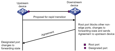
Figure 1-3 The RSTP rapid transition mechanism

Figure 1-4 The MSTP rapid transition mechanism
The combination of the RSTP rapid transition mechanism and the MSTP rapid transition mechanism is limited. For example, when the upstream switch adopts RSTP, the downstream switch adopts MSTP and does not support RSTP-compatible mode, the root port on the downstream switch receives no agreement packet from the upstream switch and thus sends no agreement packets to the upstream switch. As a result, the designated port of the upstream switch fails to transit rapidly and can only change to the Forwarding state after a period twice the Forward Delay.
Some other vendors' switches adopt proprietary spanning tree protocols that are similar to RSTP in the way to implement rapid transition on designated ports. When a switch of this kind operating as the upstream switch connects with the H3C series switch running MSTP, the upstream designated port fails to change their states rapidly.
The rapid transition function is developed to resolve this problem. When a H3C series switch running MSTP is connected ins the upstream direction to another vendor's switch running a proprietary spanning tree protocol, you can enable the rapid transition function on the ports of the H3C series switch operating as the downstream switch. Among these ports, those operating as the root ports will then send agreement packets to their upstream ports after they receive proposal packets from the upstream designated ports, instead of waiting for agreement packets from the upstream switch. This enables designated ports of the upstream switch to change their states rapidly.
1.7.2 Rapid Transition Configuration
I. Configuration prerequisites
As shown in Figure 1-5, a H3C series switch is connected to another vendor's switch. The former operates as the downstream switch, and the latter operates as the upstream switch. The network operates normally.
The upstream switch is running a proprietary spanning tree protocol that is similar to RSTP in the way to implement rapid transition on designated ports. Port 1 is a designated port.
The downstream switch is running MSTP. Port 2 is the root port.
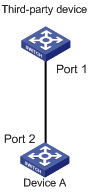
Figure 1-5 Network diagram for rapid transition configuration
II. Configuration procedure
1) Configure the rapid transition function in system view.
Follow these steps to configure the rapid transition function in system view:
|
To do ... |
Use the command ... |
Remarks |
|
Enter system view |
system-view |
— |
|
Enable the rapid transition function |
stp interface interface-type interface-number no-agreement-check |
Required By default, the rapid transition function is disabled on a port. |
2) Configure the rapid transition function in Ethernet port view.
Follow these steps to configure the rapid transition function in Ethernet port view:
|
To do ... |
Use the command ... |
Remarks |
|
Enter system view |
system-view |
— |
|
Enter Ethernet port view |
interface interface-type interface-number |
— |
|
Enable the rapid transition function |
stp no-agreement-check |
Required By default, the rapid transition function is disabled on a port. |
& Note:
l The rapid transition function can be enabled on root ports or alternate ports only.
l If you configure the rapid transition function on the designated port, the function does not take effect on the port.
1.8 VLAN-VPN Tunnel Configuration
1.8.1 Introduction
The VLAN-VPN tunnel function enables BPDUs to be transparently transmitted between geographically dispersed user networks through specified VLAN VPNs in the operator’s network, through which spanning trees can be generated across these user networks and are independent of those of the operator’s network.
As shown in Figure 1-6, the upper part is the operator’s network, and the lower part is the user network. The operator’s network comprises packet ingress/egress devices, and the user’s network has network A and network B. On the operator’s network, configure the arriving BPDU packets at the ingress to have MAC addresses in a special format, and reconvert them back to their original formats at the egress. This is how transparent transmission is implemented over the operator’s network.
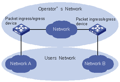
Figure 1-6 VLAN-VPN tunnel network hierarchy
1.8.2 VLAN-VPN Tunnel Configuration
Follow these steps to configure the VLAN-VPN tunnel function:
|
To do ... |
Use the command ... |
Remarks |
|
Enter system view |
system-view |
— |
|
Enable MSTP globally |
stp enable |
— |
|
Enable the VLAN-VPN tunnel function globally |
vlan-vpn tunnel |
Required |
|
Enter Ethernet port view |
interface interface-type interface-number |
Make sure that you enter the Ethernet port view of the port for which you want to enable the VLAN-VPN function. |
|
Disable MSTP for the port |
stp disable |
— |
|
Enable the VLAN VPN function for the Ethernet port |
vlan-vpn enable |
Required By default, the VLAN VPN function is disabled on all ports. |
& Note:
l The VLAN-VPN tunnel function can only be enabled on devices with STP enabled.
l To enable the VLAN-VPN function, make sure the links between operator’s networks are trunk links.
1.9 Displaying and Debugging MSTP
|
To do ... |
Use the command ... |
|
Display spanning tree-related information about the current switch |
display stp [ instance instance-id ] [ interface interface-list | slot slot-number ] [ brief ] |
|
Display the region configuration information |
display stp region-configuration |
|
Clear MSTP-related statistics |
reset stp [ interface interface-list ] |
1.10 MSTP Configuration Example
I. Network requirements
Implement MSTP in the network shown in Figure 1-7 to enable packets of different VLANs to be forwarded along different MSTIs. The detailed configurations are as follows:
l All switches in the network belong to the same MST region.
l Packets of VLAN 10, VLAN 30, VLAN 40, and VLAN 20 are forwarded along MSTI 1, MSTI 3, MSTI 4, and MSTI 0 respectively.
In this network, Switch A and Switch B operate on the convergence layer; Switch C and Switch D operate on the access layer. VLAN 10 and VLAN 30 are limited in the convergence layer and VLAN 40 is limited in the access layer. Switch A and Switch B are configured as the root bridges of MSTI 1 and MSTI 3 respectively. Switch C is configured as the root bridge of MSTI 4.
II. Network diagram
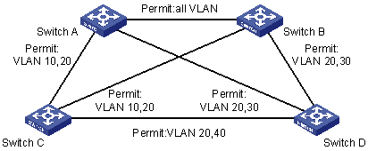
Figure 1-7 Network diagram for implementing MSTP
& Note:
The “Permit:” shown in Figure 1-7 means the corresponding link permits packets of specific VLANs.
III. Configuration procedure
1) Configure Switch A.
# Enter MST region view.
<H3C> system-view
[H3C] stp region-configuration
# Configure the MST region.
[H3C-mst-region] region-name example
[H3C-mst-region] instance 1 vlan 10
[H3C-mst-region] instance 3 vlan 30
[H3C-mst-region] instance 4 vlan 40
[H3C-mst-region] revision-level 0
# Activate the settings of the MST region.
[H3C-mst-region] active region-configuration
# Specify Switch A as the root bridge of MSTI 1.
[H3C] stp instance 1 root primary
2) Configure Switch B.
# Enter MST region view.
<H3C> system-view
[H3C] stp region-configuration
# Configure the MST region.
[H3C-mst-region] region-name example
[H3C-mst-region] instance 1 vlan 10
[H3C-mst-region] instance 3 vlan 30
[H3C-mst-region] instance 4 vlan 40
[H3C-mst-region] revision-level 0
# Activate the settings of the MST region.
[H3C-mst-region] active region-configuration
# Specify Switch B as the root bridge of MSTI 3.
[H3C] stp instance 3 root primary
3) Configure Switch C.
# Enter MST region view.
<H3C> system-view
[H3C] stp region-configuration
# Configure the MST region.
[H3C-mst-region] region-name example
[H3C-mst-region] instance 1 vlan 10
[H3C-mst-region] instance 3 vlan 30
[H3C-mst-region] instance 4 vlan 40
[H3C-mst-region] revision-level 0
# Activate the settings of the MST region.
[H3C-mst-region] active region-configuration
# Specify Switch C as the root bridge of MSTI 4.
[H3C] stp instance 4 root primary
4) Configure Switch D.
# Enter MST region view.
<H3C> system-view
[H3C] stp region-configuration
# Configure the MST region.
[H3C-mst-region] region-name example
[H3C-mst-region] instance 1 vlan 10
[H3C-mst-region] instance 3 vlan 30
[H3C-mst-region] instance 4 vlan 40
[H3C-mst-region] revision-level 0
# Activate the settings of the MST region.
[H3C-mst-region] active region-configuration
1.11 VLAN-VPN Tunnel Configuration Example
I. Network requirements
l S7500 series switches operate as the access devices of the operator’s network, that is, Switch C and Switch D in the network diagram.
l S3100 series switches operate as the access devices of the user’s network, that is, Switch A and Switch B in the network diagram.
l Switch C and Switch D connect to each other through the configured trunk port of the switch, and are enabled with the VLAN-VPN function. Thereby transparent transmission is realized between the user’s network and the operator’s network.
II. Network diagram
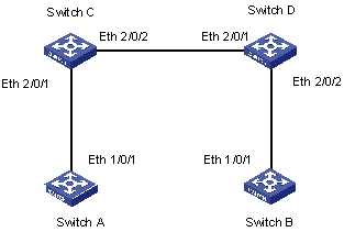
Figure 1-8 Network diagram for VLAN-VPN tunnel configuration
III. Configuration procedure
1) Configure Switch A
# Enable MSTP.
<H3C> system-view
[H3C] stp enable
# Add Ethernet 1/0/1 to VLAN 10.
[H3C] vlan 10
[H3C-Vlan10] port Ethernet 1/0/1
2) Configure Switch B
# Enable MSTP.
<H3C> system-view
[H3C] stp enable
# Add Ethernet 1/0/1 to VLAN 10.
[H3C] vlan 10
[H3C-Vlan10] port Ethernet 1/0/1
3) Configure Switch C
# Enable MSTP.
<H3C> system-view
[H3C] stp enable
# Enable the VLAN-VPN tunnel function.
[H3C] vlan-vpn tunnel
# Add Ethernet2/0/1 to VLAN 10.
[H3C] vlan 10
[H3C-Vlan10] port Ethernet 2/0/1
[H3C-Vlan10] quit
# Disable the STP feature on Ethernet2/0/1 and then enable the VLAN VPN function on it.
[H3C] interface Ethernet 2/0/1
[H3C-Ethernet2/0/1] port access vlan 10
[H3C-Ethernet2/0/1] stp disable
[H3C-Ethernet2/0/1] vlan-vpn enable
[H3C-Ethernet2/0/1] quit
# Configure Ethernet2/0/2 as a trunk port.
[H3C] interface Ethernet 2/0/2
[H3C-Ethernet2/0/2] port link-type trunk
# Add the trunk port to all VLANs.
[H3C-Ethernet2/0/2] port trunk permit vlan all
4) Configure Switch D
# Enable MSTP.
<H3C> system-view
[H3C] stp enable
# Enable the VLAN-VPN tunnel function.
[H3C] vlan-vpn tunnel
# Add Ethernet2/0/2 to VLAN 10.
[H3C] vlan 10
[H3C-Vlan10] port Ethernet 2/0/2
# Disable STP on Ethernet2/0/2 and then enable the VLAN VPN function on it.
[H3C] interface Ethernet 2/0/2
[H3C-Ethernet2/0/2] port access vlan 10
[H3C-Ethernet2/0/2] stp disable
[H3C-Ethernet2/0/2] vlan-vpn enable
[H3C-Ethernet2/0/2] quit
# Configure Ethernet2/0/1 as a trunk port.
[H3C] interface Ethernet 2/0/1
[H3C-Ethernet2/0/1] port link-type trunk
# Add the trunk port to all VLANs.
[H3C-Ethernet2/0/1] port trunk permit vlan all