- Table of Contents
-
- H3C S7500 Series Operation Manual(Release 3100 Series)-(V1.04)
- 00-1Cover
- 00-2Overview
- 01-CLI Configuration
- 02-Login Configuration
- 03-Configuration File Management Configuration
- 04-VLAN Configuration
- 05-Extended VLAN Application Configuration
- 06-IP Address-IP Performance-IPX Configuration
- 07-GVRP Configuration
- 08-QinQ Configuration
- 09-Port Basic Configuration
- 10-Link Aggregation Configuration
- 11-Port Isolation Configuration
- 12-Port Binding Configuration
- 13-DLDP Configuration
- 14-MAC Address Table Configuration
- 15-MSTP Configuration
- 16-Routing Protocol Configuration
- 17-Multicast Configuration
- 18-802.1x Configuration
- 19-AAA-RADIUS-HWTACACS-EAD Configuration
- 20-Traffic Accounting Configuration
- 21-VRRP-HA Configuration
- 22-ARP Configuration
- 23-DHCP Configuration
- 24-ACL Configuration
- 25-QoS Configuration
- 26-Mirroring Configuration
- 27-Cluster Configuration
- 28-PoE Configuration
- 29-UDP-Helper Configuration
- 30-SNMP-RMON Configuration
- 31-NTP Configuration
- 32-SSH Terminal Service Configuration
- 33-File System Management Configuration
- 34-FTP and TFTP Configuration
- 35-Information Center Configuration
- 36-DNS Configuration
- 37-System Maintenance and Debugging Configuration
- 38-HWPing Configuration
- 39-RRPP Configuration
- 40-NAT-Netstream-Policy Routing Configuration
- 41-Telnet Protection Configuration
- 42-Hardware-Dependent Software Configuration
- Related Documents
-
| Title | Size | Download |
|---|---|---|
| 19-AAA-RADIUS-HWTACACS-EAD Configuration | 859 KB |
Chapter 1 AAA & RADIUS & HWTACACS Configuration
1.1 Introduction to AAA, RADIUS and HWTACACS
1.1.2 Introduction to ISP Domain
1.1.4 Introduction to HWTACACS
1.2 AAA & RADIUS & HWTACACS Configuration Task List
1.3.1 Configuration Prerequisites
1.3.3 Configuring the Attributes of an ISP Domain
1.3.4 Configuring an AAA Scheme for an ISP Domain
1.3.5 Configuring Dynamic VLAN Assignment
1.3.6 Configuring the Attributes of a Local User
1.3.7 Cutting Down User Connections
1.4.1 Creating a RADIUS Scheme
1.4.2 Configuring RADIUS Authentication/Authorization Servers
1.4.3 Configuring RADIUS Accounting Servers
1.4.4 Configuring Shared Keys for RADIUS Packets
1.4.5 Configuring the Maximum Number of Transmission Attempts of RADIUS Requests
1.4.6 Configuring the Supported RADIUS Server Type
1.4.7 Configuring the Status of RADIUS Servers
1.4.8 Configuring the Attributes for Data to be Sent to RADIUS Servers
1.4.9 Configuring a Local RADIUS Authentication Server
1.4.10 Configuring the Timers of RADIUS Servers
1.4.11 Configuring the User Re-Authentication upon Device Restart Function
1.5.1 Creating a HWTACACS Scheme
1.5.2 Configuring HWTACACS Authentication Servers
1.5.3 Configuring HWTACACS Authorization Servers
1.5.4 Configuring HWTACACS Accounting Servers
1.5.5 Configuring Shared Keys for HWTACACS Packets
1.5.6 Configuring the Attributes for Data to be Sent to TACACS Servers
1.5.7 Configuring the Timers of TACACS Servers
1.6 Displaying and Maintaining AAA & RADIUS & HWTACACS Information
1.7 AAA & RADIUS & HWTACACS Configuration Example
1.7.1 Remote RADIUS Authentication of Telnet/SSH Users
1.7.2 Local Authentication of FTP/Telnet Users
1.7.3 TACACS Authentication, Authorization, and Accounting of Telnet Users
1.8 Troubleshooting AAA & RADIUS & HWTACACS Configuration
1.8.1 Troubleshooting the RADIUS Protocol
1.8.2 Troubleshooting the HWTACACS Protocol
2.2 Typical Network Application of EAD
2.3.1 Configuration prerequisites
Chapter 1 AAA & RADIUS & HWTACACS Configuration
When configuring AAA, RADIUS, and HWTACACS, go to these sections for information you are interested in:
l Introduction to AAA, RADIUS and HWTACACS
l AAA & RADIUS & HWTACACS Configuration Task List
l Displaying and Maintaining AAA & RADIUS & HWTACACS Information
l AAA & RADIUS & HWTACACS Configuration Example
l Troubleshooting AAA & RADIUS & HWTACACS Configuration
1.1 Introduction to AAA, RADIUS and HWTACACS
This section covers these topics:
1.1.1 Introduction to AAA
AAA is short for three security functions: authentication, authorization and accounting. It provides a uniform framework for configuring the three security functions to implement network security management.
Network security mentioned here mainly refers to access control. It controls:
l Which users can access the network server,
l Which services the users can access,
l How to charge the users who are using network resources.
Accordingly, AAA provides the following services:
I. Authentication
AAA supports the following authentication methods:
l No authentication: Users are trusted and no authentication is performed for them. Generally, this method is not recommended.
l Local authentication: User information (including user name, password, and attributes) is configured on the device. Local authentication is fast and lowers operational cost. However, the information storage capacity is limited by device hardware.
l Remote authentication: Users are authenticated remotely through the RADIUS protocol or HWTACACS protocol. The device (for example, an H3C series switch) acts as a client to communicate with the RADIUS server or TACACS server. For RADIUS protocol, both standard and extended RADIUS protocols can be used.
II. Authorization
AAA supports the following authorization methods:
l Direct authorization: Users are trusted and authorized directly.
l Local authorization: Users are authorized according to the related attributes configured for their local accounts on the device.
l RADIUS authorization: Users are authorized after they pass the RADIUS authentication. RADIUS combines authentication and authorization; you cannot perform RADIUS authorization without RADIUS authentication.
l HWTACACS authorization: Users are authorized by TACACS server.
III. Accounting
AAA supports the following accounting methods:
l No accounting: No accounting is performed for users.
l Remote accounting: User accounting is performed through a remote RADIUS server or TACACS server.
Generally, AAA is based on a client/server model, where the client acts as the managed resource and the server stores user information. This model features good scalability and facilitates the centralized management of user information.
1.1.2 Introduction to ISP Domain
An Internet service provider (ISP) domain is a group of users who belong to the same ISP. For a user name in the format of userid@isp-name, isp-name following the @ character is the ISP domain name. The access device uses userid as the user name for authentication and isp-name as the domain name.
In a multi-ISP environment, the users connected to the same access device may belong to different domains. Because the users of different ISPs may have different attributes (such as different user name and password compositions, different service types/rights), it is necessary to distinguish the users by setting ISP domains.
You can configure a set of ISP domain attributes (including AAA policy and RADIUS scheme) for each ISP domain independently in ISP domain view.
1.1.3 Introduction to RADIUS
AAA is a management framework. It can be implemented through more than one protocol. In practice, the most commonly used protocol for AAA is RADIUS.
I. What is RADIUS
RADIUS (remote authentication dial-in user service) is a distributed information exchange protocol based on a client/server model. It can prevent unauthorized access to the network and is commonly used in network environments where both high security and remote user access are required.
The RADIUS service comprises three components:
l Protocol: Based on the UDP/IP layer, RFC 2865 and 2866 define the frame format and message transfer mechanism of RADIUS, and assign port number 1812 for authentication and 1813 for accounting.
l Server: RADIUS server runs on a central computer or workstation. It stores and maintains the information about user authentication and network service access.
l Client: RADIUS clients run on the dial-in access server device. They can be deployed anywhere in the network.
RADIUS is based on a client/server model. When serving as a RADIUS client, the switch passes user information to a designated RADIUS server, and acts (such as connecting/disconnecting users) depending on the responses returned from the server. The RADIUS server receives user's connection requests, authenticates users, and returns all the required information to the switch.
Generally, the RADIUS server maintains the following three databases (as shown in Figure 1-1):
l Users: This database stores information about users (such as user name, password, protocol used, and IP address).
l Clients: This database stores the information about RADIUS clients (such as shared keys).
l Dictionary: This database stores the information used to interpret the attributes and attribute values of the RADIUS protocol.
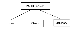
Figure 1-1 Databases in a RADIUS server
In addition, the RADIUS server can act as a proxy client to other AAA servers to provide the authentication or accounting service.
II. Basic message exchange procedure of RADIUS
The messages exchanged between a RADIUS client (a switch, for example) and the RADIUS server are verified by using a shared key. This enhances the security. The RADIUS protocol combines the authentication and authorization processes together by sending authorization information in the authentication response message. Figure 1-2 depicts the message exchange procedure between user, switch and RADIUS server.
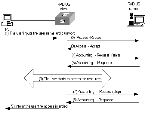
Figure 1-2 Basic message exchange procedure of RADIUS
The basic message exchange procedure of RADIUS is as follows:
1) The user enters the user name and password.
2) The RADIUS client receives the user name and password and then sends an authentication request (Access-Request) to the RADIUS server.
3) The RADIUS server compares the received user information with that in the Users database to perform authentication for the user. If the authentication succeeds, the RADIUS server sends back an authentication response (Access-Accept), which contains the information about the rights authorized to the user, to the RADIUS client. If the authentication fails, the RADIUS server returns an Access-Reject response.
4) The RADIUS client accepts or denies the user depending on the received authentication result. If the user is authenticated, the RADIUS client sends a start-accounting request (Accounting-Request, with the Status-Type filed set to start) to the RADIUS server.
5) The RADIUS server returns a start-accounting response (Accounting-Response).
6) The user starts to access the network resources.
7) The RADIUS client sends a stop-accounting request (Accounting-Request, with the Status-Type field set to stop) to the RADIUS server.
8) The RADIUS server returns a stop-accounting response (Accounting-Response).
9) The resource access for the user is ended.
III. RADIUS packet structure
RADIUS uses UDP to transmit messages. It ensures the correct message exchange between RADIUS server and client through the following mechanisms: timer management, retransmission, and backup server. Figure 1-3 depicts the structure of a RADIUS packet.
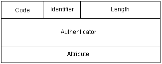
Figure 1-3 RADIUS packet structure
1) The Code field (one byte) decides the type of the RADIUS packet, as shown in Table 1-1.
Table 1-1 Description on major values of the Code field
|
Code |
Packet type |
Packet description |
|
1 |
Access-Request |
Direction: client->server. The client transmits this packet to the server to determine if the user can be connected. This packet carries user information. It must contain the User-Name attribute and may contain the following attributes: NAS-IP-Address, User-Password, and NAS-Port. |
|
2 |
Access-Accept |
Direction: server->client. The server transmits this packet to the client if all the attribute values carried in the Access-Request packet are accepted (that is, the user passes the authentication). |
|
3 |
Access-Reject |
Direction: server->client. The server transmits this packet to the client if any attribute value carried in the Access-Request packet is not accepted (that is, the user authentication fails). |
|
4 |
Accounting-Request |
Direction: client->server. The client transmits this packet to the server to request the server to start or end the accounting (whether to start or to end the accounting is determined by the Acct-Status-Type attribute in the packet). This packet carries almost the same attributes as those carried in the Access-Request packet. |
|
5 |
Accounting-Response |
Direction: server->client. The server transmits this packet to the client to notify the client that it has received the Accounting-Request packet and has correctly recorded the accounting information. |
2) The Identifier field (one byte) identifies the request and response packets. It is subject to the Attribute field and varies with the received valid responses, but it keeps unchanged during retransmission.
3) The Length field (two bytes) specifies the total length of the packet (including the Code, Identifier, Length, Authenticator, and Attribute fields). The bytes beyond the length will be regarded as padding bytes and are ignored upon receiving the packet. If the received packet is shorter than the value of this field, it will be discarded.
4) The Authenticator field (16 bytes) is used to verify the packet returned from the RADIUS server; it is also used in the password hiding algorithm. There are two kinds of authenticators: Request and Response.
5) The Attribute field contains special authentication, authorization, and accounting information to provide the configuration details of a request or response packet. This field is represented by a field triplet (Type, Length, and Value):
l The Type field (one byte) specifies the type of the attribute. Its value ranges from 1 to 255. Table 1-2 lists the attributes that are commonly used in RADIUS authentication and authorization.
l The Length field (one byte) specifies the total length of the Attribute field in bytes (including the Type, Length and Value fields).
l The Value field (up to 253 bytes) contains the information about the attribute. Its content and format are determined by the Type and Length fields.
|
Value of the Type field |
Attribute type |
Value of the Type field |
Attribute type |
|
1 |
User-Name |
23 |
Framed-IPX-Network |
|
2 |
User-Password |
24 |
State |
|
3 |
CHAP-Password |
25 |
Class |
|
4 |
NAS-IP-Address |
26 |
Vendor-Specific |
|
5 |
NAS-Port |
27 |
Session-Timeout |
|
6 |
Service-Type |
28 |
Idle-Timeout |
|
7 |
Framed-Protocol |
29 |
Termination-Action |
|
8 |
Framed-IP-Address |
30 |
Called-Station-Id |
|
9 |
Framed-IP-Netmask |
31 |
Calling-Station-Id |
|
10 |
Framed-Routing |
32 |
NAS-Identifier |
|
11 |
Filter-ID |
33 |
Proxy-State |
|
12 |
Framed-MTU |
34 |
Login-LAT-Service |
|
13 |
Framed-Compression |
35 |
Login-LAT-Node |
|
14 |
Login-IP-Host |
36 |
Login-LAT-Group |
|
15 |
Login-Service |
37 |
Framed-AppleTalk-Link |
|
16 |
Login-TCP-Port |
38 |
Framed-AppleTalk-Network |
|
17 |
(unassigned) |
39 |
Framed-AppleTalk-Zone |
|
18 |
Reply-Message |
40-59 |
(reserved for accounting) |
|
19 |
Callback-Number |
60 |
CHAP-Challenge |
|
20 |
Callback-ID |
61 |
NAS-Port-Type |
|
21 |
(unassigned) |
62 |
Port-Limit |
|
22 |
Framed-Route |
63 |
Login-LAT-Port |
The RADIUS protocol features good scalability. Attribute 26 (Vender-Specific) defined in this protocol allows a device vendor to extend RADIUS to implement functions that are not defined in standard RADIUS.
In the packet structure shown in Figure 1-4, the Vendor-ID field representing the code of the vendor occupies four bytes. The most significant byte is 0, and the other three bytes are defined in RFC1700. Here, the vendor can encapsulate multiple customized sub-attributes (Type, Length and Value) for extended RADIUS implementation.
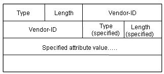
Figure 1-4 Part of the RADIUS packet containing extended attribute
1.1.4 Introduction to HWTACACS
I. What is HWTACACS
HUAWEI Terminal Access Controller Access Control System (HWTACACS) is an enhanced security protocol based on TACACS (RFC1492). Similar to the RADIUS protocol, it implements AAA for different types of users (such as PPP/VPDN login users and terminal users) through communications with TACACS servers based on a client/server model.
Compared with RADIUS, HWTACACS provides more reliable transmission and encryption, and therefore is more suitable for security control. Table 1-3 lists the primary differences between HWTACACS and RADIUS protocols.
Table 1-3 Comparison between HWTACACS and RADIUS
|
HWTACACS |
RADIUS |
|
Adopts TCP, providing more reliable network transmission. |
Adopts UDP. |
|
Encrypts the entire packet except the HWTACACS header. |
Encrypts only the password field in authentication packets. |
|
Separates authentication from authorization. For example, you can provide authentication and authorization through different TACACS servers. |
Combines authentication and authorization. |
|
Suitable for security control. |
Suitable for accounting. |
|
Supports to authorize the use of configuration commands. |
Provides no such support |
In a typical HWTACACS application, a dial-up or terminal user needs to log in to the device for operations. Acting as the HWTACACS client in this case, the switch sends the username and password to the TACACS server for authentication. After passing authentication and being authorized, the user can log in to the switch to perform operations, as shown in Figure 1-5.
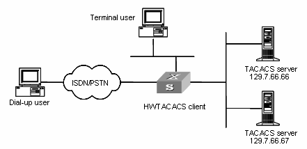
Figure 1-5 Network diagram for a typical HWTACACS application
II. Basic message exchange procedure in HWTACACS
For example, HWTACACS is used to implement authentication, authorization, and accounting for a telnet user. Figure 1-6 illustrates the basic message exchange procedure:
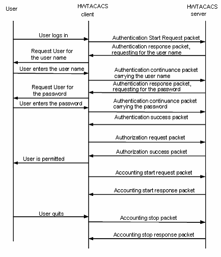
Figure 1-6 The AAA implementation procedure for a telnet user
The basic message exchange procedure is as follows:
1) A user requests access to the switch; the TACACS client sends an authentication start request packet to TACACS server upon receipt of the request.
2) The TACACS server sends back an authentication response requesting for the username; the TACACS client asks the user for the username upon receipt of the response.
3) The TACACS client sends an authentication continuance packet carrying the username after receiving the username from the user.
4) The TACACS server sends back an authentication response, requesting for the password. Upon receipt of the response, the TACACS client requests the user for the login password.
5) After receiving the login password, the TACACS client sends an authentication continuance packet carrying the login password to the TACACS server.
6) The TACACS server sends back an authentication response indicating that the user has passed the authentication.
7) The TACACS client sends the user authorization request packet to the TACACS server.
8) The TACACS server sends back the authorization response, indicating that the user has passed the authorization.
9) Upon receipt of the response indicating an authorization success, the TACACS client pushes the configuration interface of the switch to the user.
10) The TACACS client sends an accounting start request packet to the TACACS server.
11) The TACACS server sends back an accounting response, indicating that it has received the accounting start request.
12) The user logs out; the TACACS client sends an accounting stop request to the TACACS server.
13) The TACACS server sends back an accounting stop packet, indicating that the accounting stop request has been received.
1.2 AAA & RADIUS & HWTACACS Configuration Task List
|
To do... |
Remarks |
Related section |
|
|
AAA configuration |
Create an ISP domain |
Required |
|
|
Configure the attributes of the ISP domain |
Optional |
||
|
Configure an AAA scheme for the ISP domain |
Required If local authentication is adopted, refer to Configuring the Attributes of a Local User. If RADIUS authentication is adopted, refer to RADIUS Configuration. |
||
|
Configure dynamic VLAN assignment |
Optional |
||
|
Configure the attributes of a local user |
Optional |
||
|
Cut down user connections forcibly |
Optional |
||
|
RADIUS configuration |
Create a RADIUS scheme |
Required |
|
|
Configure RADIUS authentication/authorization servers |
Required |
||
|
Configure RADIUS accounting servers |
Required |
||
|
Configure shared keys for RADIUS packets |
Optional |
||
|
Configure the maximum number of transmission attempts of RADIUS requests |
Optional |
Configuring the Maximum Number of Transmission Attempts of RADIUS Requests |
|
|
Configure the supported RADIUS server type |
Optional |
||
|
Configure the status of RADIUS servers |
Optional |
||
|
Configure the attributes for data to be sent to RADIUS servers |
Optional |
Configuring the Attributes for Data to be Sent to RADIUS Servers |
|
|
Configure a local RADIUS authentication server |
Optional |
||
|
Configure the timers for RADIUS servers |
Optional |
||
|
Configure the user re-authentication upon device restart function |
Optional |
Configuring the User Re-Authentication upon Device Restart Function |
|
|
HWTACACS configuration |
Create a HWTACACS scheme |
Required |
|
|
Configure HWTACACS authentication servers |
Required |
||
|
Configure HWTACACS authorization servers |
Required |
||
|
Configure HWTACACS accounting servers |
Optional |
||
|
Configure shared keys for HWTACACS packets |
Optional |
||
|
Configure the attributes for data to be sent to TACACS servers |
Optional |
Configuring the Attributes for Data to be Sent to TACACS Servers |
|
|
Configure the timers of TACACS servers |
Optional |
||
1.3 AAA Configuration
The goal of AAA configuration is to protect network devices against unauthorized access and at the same time provide network access services to authorized users. If you need to use ISP domains to implement AAA management on access users, you need to configure the ISP domains.
This section covers these topics:
l Configuring the Attributes of an ISP Domain
l Configuring an AAA Scheme for an ISP Domain
l Configuring Dynamic VLAN Assignment
l Configuring the Attributes of a Local User
l Cutting Down User Connections
1.3.1 Configuration Prerequisites
To implement remote AAA, you need to create a RADIUS or HWTACACS scheme.
l RADIUS scheme (radius-scheme): You can reference a configured RADIUS scheme to implement AAA services. For the configuration of RADIUS scheme, refer to RADIUS Configuration.
l HWTACACS scheme (hwtacacs-scheme): You can reference a configured HWTACACS scheme to implement AAA services. For the configuration of HWTACACS scheme, refer to HWTACACS Configuration.
1.3.2 Creating an ISP Domain
Table 1-5 Create an ISP domain
|
To do... |
Use the command... |
Remarks |
|
Enter system view |
system-view |
— |
|
Create an ISP domain, enter the view of an existing ISP domain, or configure the default ISP domain |
domain { isp-name | default { disable | enable isp-name } } |
Required The default ISP domain is system. |
1.3.3 Configuring the Attributes of an ISP Domain
Table 1-6 Configure the attributes of an ISP domain
|
To do... |
Use the command... |
Remarks |
|
Enter system view |
system-view |
— |
|
Create an ISP domain or enter the view of an existing ISP domain |
domain isp-name |
Required |
|
Activate/deactivate the ISP domain |
state { active | block } |
Optional By default, once an ISP domain is created, it is in the active state and all the users in this domain are allowed to access the network. |
|
Set the maximum number of access users that can be contained in the ISP domain |
access-limit { disable | enable max-user-number } |
Optional After an ISP domain is created, the number of access users it can contain is unlimited by default. |
|
Set the user idle-cut function |
idle-cut { disable | enable minute flow } |
Optional By default, user idle-cut function is disabled. |
|
Turn on/off the accounting-optional switch |
accounting optional |
Optional By default, once an ISP domain is created, the accounting-optional switch is turned off. |
|
Set the messenger function |
messenger time { enable limit interval | disable } |
Optional By default, the messenger function is disabled. |
|
Set the self-service server location function |
self-service-url { disable | enable url-string } |
Optional By default, the self-service server location function is disabled. |
![]() Caution:
Caution:
l When a user is to be charged, if the system does not find any available accounting server or fails to communicate with any accounting server, it will not disconnect the user as long as the accounting optional command has been executed.
l The self-service server location function must cooperate with a RADIUS server (such as CAMS) that supports self-service. Through self-service, users can manage and control their accounts or card numbers by themselves. A server installed with self-service software is called a self-service server.
& Note:
H3C’s CAMS Server is a service management system used to manage networks and secure networks and user information. Cooperating with other network devices (such as switches) in a network, the CAMS Server implements the AAA (authentication, authorization and accounting) services and rights management.
1.3.4 Configuring an AAA Scheme for an ISP Domain
You can use the scheme command to specify an AAA scheme. If you specify a RADIUS or HWTACACS scheme, the authentication, authorization, and accounting will be uniformly implemented by the RADIUS server or TACACS server specified in the RADIUS or HWTACACS scheme.
Table 1-7 Configure an AAA scheme for an ISP domain
|
To do... |
Use the command... |
Remarks |
|
Enter system view |
system-view |
— |
|
Create an ISP domain or enter the view of an existing ISP domain |
domain isp-name |
Required |
|
Configure an AAA scheme for the ISP domain |
scheme { local | none | radius-scheme radius-scheme-name [ local ] | hwtacacs-scheme hwtacacs-scheme-name [ local ] } |
Required By default, the ISP domain uses the local AAA scheme. |
|
Configure a RADIUS scheme for the ISP domain |
radius-scheme radius-scheme-name |
Optional This function can also be implemented by using the scheme command to specify the RADIUS scheme to be used. |
![]() Caution:
Caution:
l You can execute the scheme command with the radius-scheme-name argument to adopt an already configured RADIUS scheme to implement all the three AAA functions. If you adopt the local scheme, only the authentication and authorization functions are implemented, the accounting function cannot be implemented.
l If you execute the scheme radius-scheme radius-scheme-name local command, the local scheme becomes the secondary scheme in case the RADIUS server does not respond normally. That is, if the communication between the switch and the RADIUS server is normal, no local authentication is performed; otherwise, local authentication is performed.
l If you execute the scheme hwtacacs-scheme radius-scheme-name local command, the local scheme becomes the secondary scheme in case the TACACS server does not respond normally. That is, if the communication between the switch and the TACACS server is normal, no local authentication is performed; otherwise, local authentication is performed.
l If you adopt local or none as the primary scheme, local authentication is performed or no authentication is performed. In this case, you cannot use the RADIUS scheme at the same time.
1.3.5 Configuring Dynamic VLAN Assignment
The dynamic VLAN assignment feature enables a switch to dynamically add the switch ports with successfully authenticated users to different VLANs according to the attributes assigned by the RADIUS server, so as to control the network resources that different users can access.
Currently, the switch supports the RADIUS authentication server to assign the following two types of VLAN IDs: integer and string.
l Integer: If the RADIUS server assigns integer type of VLAN IDs, you can set the VLAN assignment mode to integer on the switch. Then, upon receiving an integer ID assigned by the RADIUS authentication server, the switch adds the port to the VLAN whose VLAN ID is equal to the assigned integer ID. If no such a VLAN exists, the switch first creates a VLAN with the assigned ID, and then adds the port to the newly created VLAN.
l String: If the RADIUS server assigns string type of VLAN IDs, you can set the VLAN assignment mode to string on the switch. Then, upon receiving a string ID assigned by the RADIUS authentication server, the switch compares the ID with existing VLAN names on the switch. If it finds a match, it adds the port to the corresponding VLAN. Otherwise, the VLAN assignment fails and the user cannot pass the authentication.
The switch supports the integer mode and string mode of dynamic VLAN assignments to adapt to authentication server. Different servers assign VLANs in different ways. You are recommended to configure the switch based on the mode of dynamic VLAN assignment used by the server. Table 1-8 lists some common VLAN assignment modes for RADIUS server.
Table 1-8 Common VLAN assignment modes for RADIUS server
|
Server type |
Dynamic VLAN assignment mode |
|
CAMS |
Integer (For the latest version, whether the mode is integer or string depends on attribute value.) |
|
ACS |
String |
|
FreeRADIUS |
Determined by attribute value (A value of 100 represents the integer mode and a value of "100" represents the string mode). |
|
Shiva Access Manager |
String |
|
Steel-Belted Radius Administrator |
String |
In actual applications, to use this feature together with Guest VLAN, set port control to port-based mode.
Table 1-9 Configure dynamic VLAN assignment
|
Use the command... |
Remarks |
|
|
Enter system view |
system-view |
— |
|
Create an ISP domain and enter its view |
domain isp-name |
— |
|
Set the VLAN assignment mode |
vlan-assignment-mode { integer | string } |
Optional By default, the VLAN assignment mode is integer. |
|
Create a VLAN and enter its view |
vlan vlan-id |
— |
|
Set a VLAN name for VLAN assignment |
name string |
This operation is required if the VLAN assignment mode is set to string. |
![]() Caution:
Caution:
l In string mode, if the VLAN ID assigned by the RADIUS server is a character string containing only digits (for example, 1024), the switch first regards it as an integer VLAN ID: the switch transforms the string to an integer value and determines if the value is in the valid VLAN ID range; if it is, the switch adds the authenticated port to the VLAN with the integer value as the VLAN ID (VLAN 1024, for example).
l To implement dynamic VLAN assignment on a port enabled with both MSTP and 802.1x, make sure you configure the MSTP port as an edge port.
1.3.6 Configuring the Attributes of a Local User
When local scheme is chosen as the AAA scheme, you should create local users on the switch and configure the related attributes.
Local users are users set on the switch, with each user uniquely identified by a user name. To make a user who is requesting network service pass through the local authentication, you should add an entry in the local user database on the switch for the user.
Table 1-10 Configure the attributes of a local user
|
To do... |
Use the command... |
Remarks |
|
Enter system view |
system-view |
— |
|
Set the password display mode of all local users |
local-user password-display-mode { cipher-force | auto } |
Optional By default, the password display mode of all access users is auto, indicating the passwords of access users are displayed in the modes set with the password command. |
|
Add a local user and enter local user view |
local-user user-name |
Required By default, there is no local user in the system. |
|
Set a password for the specified user |
password { simple | cipher } password |
Optional |
|
Set the state of the specified user |
state { active | block } |
Optional By default, the local users are in the active state once they are created, that is, they are allowed to request network services. |
|
Authorize the user to access the specified type(s) of service(s) |
service-type { ftp | lan-access | { telnet | ssh | terminal }* [ level level ] } |
Required By default, the system does not authorize the user to access any service. |
|
Set the priority level of the user |
level level |
Optional By default, the priority level of the user is 0. |
|
Set the attributes of the user whose service type is lan-access |
attribute { ip ip-address | mac mac-address | idle-cut second | access-limit max-user-number | vlan vlan-id | location { nas-ip ip-address port port-number | port port-number } }* |
Optional If the user is bound to a remote port, you need to specify the nas-ip parameter (the following ip-address is 127.0.0.1 by default, representing this device). If the user is bound to a local port, the nas-ip keyword is not required. |
![]() Caution:
Caution:
l The character string of user-name cannot contain “/”, “:”, “*”, “?”, “<” or “>”. Moreover, “@” can be used no more than once.
l After the local-user password-display-mode cipher-force command is executed, all the passwords will be displayed in cipher mode even if you have specified to display user passwords in plain text by using the password command.
l If the configured authentication method (local or RADIUS) requires a user name and a password, the command level that a user can access after login is determined by the priority level of the user. For SSH users, when they use RSA shared keys for authentication, the commands they can access are determined by the levels set on their user interfaces.
l If the configured authentication method is none or requires a password, the command level that a user can access after login is determined by the level of the user interface.
1.3.7 Cutting Down User Connections
Table 1-11 Cut down user connection
|
To do... |
Use the command... |
Remarks |
|
Enter system view |
system-view |
— |
|
Cut down user connections forcibly |
cut connection { all | access-type { dot1x | mac-authentication } | domain isp-name | interface interface-type interface-number | ip ip-address | mac mac-address | radius-scheme radius-scheme-name | vlan vlan-id | ucibindex ucib-index | user-name user-name } |
Required |
& Note:
l You can use the display connection command to display Telnet user connections, but cannot use the cut connection command to cut down their connections.
l You can use neither the display connection command to display FTP or SFTP user connections, nor the cut connection command to cut down their connections..
1.4 RADIUS Configuration
RADIUS protocol is configured scheme by scheme. In an actual network environment, you can either use a single RADIUS server or two RADIUS servers (primary and secondary servers with the same configuration but different IP addresses) in a RADIUS scheme. After creating a new RADIUS scheme, you should configure the IP address and UDP port number of each RADIUS server you want to use in this scheme. These RADIUS servers fall into two types: authentication/authorization, and accounting. And for each kind of server, you can configure two servers in a RADIUS scheme: primary server and secondary server. A RADIUS scheme has the following attributes: IP addresses of the primary and secondary servers, shared keys, and types of the RADIUS servers.
In an actual network environment, you can configure the above parameters as required. But you should configure at least one authentication/authorization server and one accounting server, and at the same time, you should keep the RADIUS service port settings on the switch consistent with those on the RADIUS servers.
& Note:
Actually, the RADIUS protocol configuration only defines the parameters used for information exchange between the switch and the RADIUS servers. To make these parameters take effect, make sure you reference the RADIUS scheme configured with these parameters in an ISP domain view. For specific configuration commands, refer to AAA Configuration.
This section covers these topics:
l Configuring RADIUS Authentication/Authorization Servers
l Configuring RADIUS Accounting Servers
l Configuring Shared Keys for RADIUS Packets
l Configuring the Maximum Number of Transmission Attempts of RADIUS Requests
l Configuring the Supported RADIUS Server Type
l Configuring the Status of RADIUS Servers
l Configuring the Attributes for Data to be Sent to RADIUS Servers
l Configuring a Local RADIUS Authentication Server
l Configuring the Timers of RADIUS Servers
l Configuring the User Re-Authentication upon Device Restart Function
1.4.1 Creating a RADIUS Scheme
The RADIUS protocol is configured scheme by scheme. You should first create a RADIUS scheme and enter its view before performing other RADIUS protocol configurations.
Table 1-12 Create a RADIUS scheme
|
To do... |
Use the command... |
Remarks |
|
Enter system view |
system-view |
— |
|
Create a RADIUS scheme and enter its view |
radius scheme radius-scheme-name |
Required By default, a RADIUS scheme named system has already been created in the system. |
![]() Caution:
Caution:
A RADIUS scheme can be referenced by multiple ISP domains at the same time.
1.4.2 Configuring RADIUS Authentication/Authorization Servers
Table 1-13 Configure RADIUS authentication/authorization server
|
To do... |
Use the command... |
Remarks |
|
Enter system view |
system-view |
— |
|
Create a RADIUS scheme and enter its view |
radius scheme radius-scheme-name |
Required By default, a RADIUS scheme named system has already been created in the system. |
|
Set the IP address and port number of the primary RADIUS authentication/authorization server |
primary authentication ip-address [ port-number ] |
Required By default, the IP address and UDP port number of the primary server are 0.0.0.0 and 1812 respectively. |
|
Set the IP address and port number of the secondary RADIUS authentication/authorization server |
secondary authentication ip-address [ port-number ] |
Optional By default, the IP address and UDP port number of the secondary server are 0.0.0.0 and 1812 respectively. |
![]() Caution:
Caution:
l The authentication response sent from the RADIUS server to the RADIUS client carries the authorization information. Therefore, no separate authorization server can be specified.
l In an actual network environment, you can either specify two RADIUS servers as the primary and secondary authentication/authorization servers respectively, or specify only one server as both the primary and secondary authentication/authorization servers.
l The IP address and port number of the primary authentication server used by the default RADIUS scheme system are 127.0.0.1 and 1645.
1.4.3 Configuring RADIUS Accounting Servers
Table 1-14 Configure RADIUS accounting server
|
To do... |
Use the command... |
Remarks |
|
Enter system view |
system-view |
— |
|
Create a RADIUS scheme and enter its view |
radius scheme radius-scheme-name |
Required By default, a RADIUS scheme named system has already been created in the system. |
|
Set the IP address and port number of the primary RADIUS accounting server |
primary accounting ip-address [ port-number ] |
Required By default, the IP address and UDP port number of the primary accounting server are 0.0.0.0 and 1813. |
|
Set the IP address and port number of the secondary RADIUS accounting server |
secondary accounting ip-address [ port-number ] |
Optional By default, the IP address and UDP port number of the secondary accounting server are 0.0.0.0 and 1813. |
|
Enable stop-accounting packet buffering |
stop-accounting-buffer enable |
Optional By default, stop-accounting packet buffering is enabled. |
|
Set the maximum number of transmission attempts of the buffered stop-accounting packets. |
retry stop-accounting retry-times |
Optional By default, the system tries at most 500 times to transmit a buffered stop-accounting request. |
|
Set the maximum number of real-time accounting request attempts |
retry realtime-accounting retry-times |
Optional By default, the maximum number of real-time accounting request attempts is 5. After this number is reached, the user connection is cut down. |
![]() Caution:
Caution:
l In an actual network environment, you can either specify two RADIUS servers as the primary and secondary accounting servers respectively, or specify only one server as both the primary and secondary accounting servers. In addition, because RADIUS uses different UDP ports to send/receive authentication/authorization packets and the accounting packets, you need to set a port number for accounting different from that set for authentication/authorization.
l If the RADIUS server does not respond to such a request, the switch should first buffer the request on itself, and then retransmit the request to the RADIUS accounting server until it gets a response, or the maximum number of transmission attempts is reached (in this case, it discards the request).
l You can set the maximum number of real-time accounting request attempts in the case that the accounting fails. If the switch makes all the allowed real-time accounting request attempts but fails to perform accounting, it cuts down the connection of the user.
l The IP address and the port number of the default primary accounting server system are 127.0.0.1 and 1646.
l Currently, RADIUS does not support the accounting of FTP users.
1.4.4 Configuring Shared Keys for RADIUS Packets
The RADIUS client and server adopt MD5 algorithm to encrypt the RADIUS packets exchanged with each other. The two parties verify the validity of the exchanged packets by using the shared keys that have been set on them, and can accept and respond to the packets sent from each other only if both of them have the same shared keys.
Table 1-15 Configure shared keys for RADIUS packets
|
To do... |
Use the command... |
Remarks |
|
Enter system view |
system-view |
— |
|
Create a RADIUS scheme and enter its view |
radius scheme radius-scheme-name |
Required By default, a RADIUS scheme named system has already been created in the system. |
|
Set a shared key for the RADIUS authentication/authorization packets |
key authentication string |
Required |
|
Set a shared key for the RADIUS accounting packets |
key accounting string |
Required |
![]() Caution:
Caution:
You need to set the share keys separately for the authentication/authorization packets and the accounting packets if the authentication/authorization server and the accounting server are different devices and the shared keys on the two servers are also different.
1.4.5 Configuring the Maximum Number of Transmission Attempts of RADIUS Requests
The communication through RADIUS is unreliable because this protocol adopts UDP packets to carry data. Therefore, it is necessary for the switch to retransmit a RADIUS request if it gets no response from the RADIUS server after the response timeout timer expires. If the maximum number of transmission attempts is reached and the switch still receives no answer, the switch considers that the authentication fails.
Table 1-16 Configure the maximum transmission attempts of RADIUS request
|
To do... |
Use the command... |
Remarks |
|
Enter system view |
system-view |
— |
|
Create a RADIUS scheme and enter its view |
radius scheme radius-scheme-name |
Required By default, a RADIUS scheme named system has already been created in the system. |
|
Set the maximum number of transmission attempts of RADIUS requests |
retry retry-times |
Optional By default, the system tries three times to transmit a RADIUS request. |
1.4.6 Configuring the Supported RADIUS Server Type
Table 1-17 Configure the supported RADIUS server type
|
To do... |
Use the command... |
Remarks |
|
Enter system view |
system-view |
— |
|
Create a RADIUS scheme and enter its view |
radius scheme radius-scheme-name |
Required By default, a RADIUS scheme named system has already been created in the system. |
|
Specify the type of RADIUS server supported by the switch |
server-type { extended | standard } |
Optional By default, the switch supports the standard type of RADIUS server. The type of RADIUS server in the default RADIUS scheme system is extended. |
1.4.7 Configuring the Status of RADIUS Servers
For the primary and secondary servers (authentication/authorization servers, or accounting servers) in a RADIUS scheme:
When the switch fails to communicate with the primary server due to some server trouble, the switch will actively exchange packets with the secondary server.
After the time the primary server keeps in the block state exceeds the time set with the timer quiet command, the switch will try to communicate with the primary server again when it receives a RADIUS request. If the primary server recovers, the switch immediately restores the communication with the primary server instead of communicating with the secondary server, and at the same time restores the status of the primary server to the active state while keeping the status of the secondary server unchanged.
When both the primary and secondary servers are in active or block state, the switch sends packets to the primary server only.
Table 1-18 Set the status of RADIUS servers
|
To do... |
Use the command... |
Remarks |
|
Enter system view |
system-view |
— |
|
Create a RADIUS scheme and enter its view |
radius scheme radius-scheme-name |
Required By default, a RADIUS scheme named system has already been created in the system. |
|
Set the status of the primary RADIUS authentication/authorization server |
state primary authentication { block | active } |
Optional By default, all the RADIUS servers in a customized RADIUS scheme are in the block state, and all the RADIUS servers configured with IP addresses are in the active state. |
|
Set the status of the primary RADIUS accounting server |
state primary accounting { block | active } |
|
|
Set the status of the secondary RADIUS authentication/authorization server |
state secondary authentication { block | active } |
|
|
Set the status of the secondary RADIUS accounting server |
state secondary accounting { block | active } |
1.4.8 Configuring the Attributes for Data to be Sent to RADIUS Servers
Table 1-19 Configure the attributes for data to be sent to the RADIUS servers
|
To do... |
Use the command... |
Remarks |
|
Enter system view |
system-view |
— |
|
Create a RADIUS scheme and enter its view |
radius scheme radius-scheme-name |
Required By default, a RADIUS scheme named system has already been created in the system. |
|
Set the format of the user names to be sent to RADIUS servers |
user-name-format { with-domain | without-domain } |
Optional By default, the user names sent from the switch to RADIUS servers carry ISP domain names. |
|
Set the units of measure for data flows sent to RADIUS servers |
data-flow-format data { byte | giga-byte | kilo-byte | mega-byte } packet { giga-packet | kilo-packet | mega- packet | one-packet } |
Optional By default, in a RADIUS scheme, the unit of measure for data is byte and that for packets is one-packet. |
|
Set the source IP address used by the switch to send RADIUS packets |
RADIUS scheme view nas-ip ip-address |
Optional By default, no source IP address is specified; and the IP address of the outbound interface is used as the source IP address. |
|
System view radius nas-ip ip-address |
![]() Caution:
Caution:
l Generally, the access users are named in the userid@isp-name format. isp-name behind the @ character represents the ISP domain name, by which the device determines which ISP domain it should ascribe the user to. However, some old RADIUS servers cannot accept the user names that carry ISP domain names. In this case, it is necessary to remove the domain names carried in the user names before sending the user names to the RADIUS server. For this reason, the user-name-format command is designed for you to specify whether or not ISP domain names are to be carried in the user names sent to the RADIUS server.
l For a RADIUS scheme, if you have specified that no ISP domain names are to be carried in the user names, you should not adopt this RADIUS scheme in more than one ISP domain. Otherwise, such errors may occur: the RADIUS server regards two different users having the same name but belonging to different ISP domains as the same user (because the usernames sent to it are the same).
l In the default RADIUS scheme system, no ISP domain names are carried in the usernames by default.
1.4.9 Configuring a Local RADIUS Authentication Server
Table 1-20 Configure local RADIUS authentication server
|
To do... |
Use the command... |
Remarks |
|
Enter system view |
system-view |
— |
|
Create a local RADIUS authentication server |
local-server nas-ip ip-address key password |
Required By default, a local RADIUS authentication server has already been created, whose NAS-IP is 127.0.0.1 |
![]() Caution:
Caution:
l When you use the local RADIUS authentication server function, the UDP port number for the authentication/authorization service must be 1645, the UDP port number for the accounting service is 1646, and the IP addresses of the servers must be set to the addresses of the switch.
l The packet encryption key set by the local-server command with the key password parameter must be identical with the authentication/authorization packet encryption key set by the key authentication command in RADIUS scheme view.
l The switch supports up to 16 local RADIUS authentication servers (including the default local RADIUS authentication server).
1.4.10 Configuring the Timers of RADIUS Servers
If the switch gets no response from the RADIUS server after sending out a RADIUS request (authentication/authorization request or accounting request) and waiting for a period of time, it should retransmit the packet to ensure that the user can obtain the RADIUS service. This wait time is called response timeout time of RADIUS servers; and the timer in the switch system that is used to control this wait time is called the response timeout timer of RADIUS servers.
For the primary and secondary servers (authentication/authorization servers, or accounting servers) in a RADIUS scheme:
When the switch fails to communicate with the primary server due to some server trouble, the switch will actively exchange packets with the secondary server.
After the time the primary server keeps in the block state exceeds the time set with the timer quiet command, the switch will try to communicate with the primary server again when it receives a RADIUS request. If the primary server recovers, the switch immediately restores the communication with the primary server instead of communicating with the secondary server, and at the same time restores the primary server to the active state while keeping the state of the secondary server unchanged.
To charge the users in real time, you should set the interval of real-time accounting. After the setting, the switch sends the accounting information of online users to the RADIUS server at regular intervals.
Table 1-21 Set the timers of RADIUS server
|
To do... |
Use the command... |
Remarks |
|
Enter system view |
system-view |
— |
|
Create a RADIUS scheme and enter its view |
radius scheme radius-scheme-name |
Required By default, a RADIUS scheme named system has already been created in the system. |
|
Set the response timeout time of RADIUS servers |
timer response-timeout seconds |
Optional By default, the response timeout timer of RADIUS servers expires in three seconds. |
|
timer seconds |
||
|
Set the wait time for the primary server to restore the active state |
timer quiet minutes |
Optional By default, the primary server waits five minutes before restoring the active state. |
|
Set the real-time accounting interval |
timer realtime-accounting minutes |
Optional By default, the real-time accounting interval is 12 minutes. |
1.4.11 Configuring the User Re-Authentication upon Device Restart Function
& Note:
The function applies to the environment where the RADIUS authentication/accounting server is CAMS.
In an environment with a CAMS server, if the switch reboots after an exclusive user (a user whose concurrent online number is set to 1 on the CAMS) gets authenticated and authorized and begins being charged, the CAMS will give a prompt that the user has already been online when the user re-logs in to the switch before CAMS performs online user detection, and the user cannot get authenticated. In this case, the user can access the network again only after the CAMS administrator manually removes the online information of the user.
The user re-authentication upon device restart function is designed to resolve the above problem. After this function is enabled, every time the switch restarts:
1) The switch generates an Accounting-On packet, which mainly contains the following information: NAS-ID, NAS-IP address (source IP address), and session ID.
2) The switch sends the Accounting-On packet to CAMS at regular intervals.
3) Once the CAMS receives the Accounting-On packet, it sends a response to the switch. At the same time it finds and deletes the original online information of the users who access the network through the switch before the restart according to the information contained in this packet (NAS-ID, NAS-IP address and session ID), and ends the accounting of the users based on the last accounting update packet.
4) Once the switch receives the response from the CAMS, it stops sending other Accounting-On packets.
5) If the switch does not receive any response from the CAMS after the number of the Accounting-On packets it has sent reaches the configured maximum number, it does not send any more Accounting-On packets.
& Note:
The switch can automatically generate the main attributes (NAS-ID, NAS-IP address and session ID) in the Accounting-On packets. However, you can also manually configure the NAS-IP address with the nas-ip command. If you choose to manually configure the attribute, be sure to configure an appropriate and legal IP address. If this attribute is not configured, the switch will automatically use the IP address of the VLAN interface as the NAS-IP address.
Table 1-22 Enable the user re-authentication upon device restart function
|
To do... |
Use the command... |
Remarks |
|
Enter system view |
system-view |
— |
|
Enter RADIUS scheme view |
radius scheme radius-scheme-name |
— |
|
Enable the user re-authentication upon device restart function |
accounting-on enable [ send times | interval interval ] |
By default, this function is disabled, and the system can send at most 15 Accounting-On packets consecutively at intervals of three seconds. |
1.5 HWTACACS Configuration
This section covers these topics:
l Configuring HWTACACS Authentication Servers
l Configuring HWTACACS Authorization Servers
l Configuring HWTACACS Accounting Servers
l Configuring Shared Keys for HWTACACS Packets
l Configuring the Attributes for Data to be Sent to TACACS Servers
l Configuring the Timers of TACACS Servers
1.5.1 Creating a HWTACACS Scheme
HWTACACS protocol is configured scheme by scheme. Therefore, you need to create a HWTACACS scheme and enter HWTACACS view before you perform other configuration tasks.
Table 1-23 Create a HWTACACS scheme
|
To do... |
Use the command... |
Remarks |
|
Enter system view |
system-view |
— |
|
Create a HWTACACS scheme and enter HWTACACS view |
hwtacacs scheme hwtacacs-scheme-name |
Required By default, no HWTACACS scheme exists. |
![]() Caution:
Caution:
The system supports up to 16 HWTACACS schemes. You can only delete the schemes that are not being used.
1.5.2 Configuring HWTACACS Authentication Servers
Table 1-24 Configure HWTACACS authentication servers
|
To do... |
Use the command... |
Remarks |
|
Enter system view |
system-view |
— |
|
Create a HWTACACS scheme and enter its view |
hwtacacs scheme hwtacacs-scheme-name |
Required By default, no HWTACACS scheme exists. |
|
Set the IP address and port number of the primary TACACS authentication server |
primary authentication ip-address [ port ] |
Required By default, the IP address of the primary authentication server is 0.0.0.0, and the port number is 0. |
|
Set the IP address and port number of the secondary TACACS authentication server |
secondary authentication ip-address [ port ] |
Required By default, the IP address of the secondary authentication server is 0.0.0.0, and the port number is 0. |
![]() Caution:
Caution:
l The primary and secondary authentication servers cannot use the same IP address. Otherwise, the system will prompt unsuccessful configuration.
l You can remove a server only when it is not being used by any active TCP connection for sending authentication packets.
1.5.3 Configuring HWTACACS Authorization Servers
Table 1-25 Configure TACACS authorization servers
|
To do... |
Use the command... |
Remarks |
|
Enter system view |
system-view |
— |
|
Create a HWTACACS scheme and enter its view |
hwtacacs scheme hwtacacs-scheme-name |
Required By default, no HWTACACS scheme exists. |
|
Set the IP address and port number of the primary TACACS authorization server |
primary authorization ip-address [ port ] |
Required By default, the IP address of the primary authorization server is 0.0.0.0, and the port number is 0. |
|
Set the IP address and port number of the secondary TACACS authorization server |
secondary authorization ip-address [ port ] |
Required By default, the IP address of the secondary authorization server is 0.0.0.0, and the port number is 0. |
![]() Caution:
Caution:
l The primary and secondary authorization servers cannot use the same IP address. Otherwise, the system will prompt unsuccessful configuration.
l You can remove a server only when it is not being used by any active TCP connection for sending authorization packets.
1.5.4 Configuring HWTACACS Accounting Servers
Table 1-26 Configure HWTACACS accounting servers
|
To do... |
Use the command... |
Remarks |
|
Enter system view |
system-view |
— |
|
Create a HWTACACS scheme and enter its view |
hwtacacs scheme hwtacacs-scheme-name |
Required By default, no HWTACACS scheme exists. |
|
Set the IP address and port number of the primary TACACS accounting server |
primary accounting ip-address [ port ] |
Required By default, the IP address of the primary accounting server is 0.0.0.0, and the port number is 0. |
|
Set the IP address and port number of the secondary TACACS accounting server |
secondary accounting ip-address [ port ] |
Required By default, the IP address of the secondary accounting server is 0.0.0.0, and the port number is 0. |
|
Enable the stop-accounting packets retransmission function and set the maximum number of attempts |
retry stop-accounting retry-times |
Optional By default, the stop-accounting packets retransmission function is enabled and the system can transmit a stop-accounting request for 100 times. |
![]() Caution:
Caution:
l The primary and secondary accounting servers cannot use the same IP address. Otherwise, the system will prompt unsuccessful configuration.
l You can remove a server only when it is not being used by any active TCP connection for sending accounting packets.
l Currently, HWTACACS does not support the accounting of FTP users.
1.5.5 Configuring Shared Keys for HWTACACS Packets
When using a TACACS server as an AAA server, you can set a key to improve the communication security between the router and the TACACS server.
The TACACS client (device system) and server adopt MD5 algorithm to encrypt the exchanged HWTACACS packets. The two parties verify the validity of the exchanged packets by using the shared keys that have been set on them, and can accept and respond to the packets sent from each other only if both of them have the same shared keys. Therefore, make sure the shared key set on the device and that on TACACS server are the same.
Table 1-27 Configure shared keys for HWTACACS packets
|
To do... |
Use the command... |
Remarks |
|
Enter system view |
system-view |
— |
|
Create a HWTACACS scheme and enter its view |
hwtacacs scheme hwtacacs-scheme-name |
Required By default, no HWTACACS scheme exists. |
|
Set a shared key for the HWTACACS accounting/authentication/authorization packets |
key { accounting | authorization | authentication } string |
Required By default, the TACACS server does not have a key. |
1.5.6 Configuring the Attributes for Data to be Sent to TACACS Servers
Table 1-28 Configure the attributes for data to be sent to TACACS servers
|
To do... |
Use the command... |
Remarks |
|
Enter system view |
system-view |
— |
|
Create a HWTACACS scheme and enter its view |
hwtacacs scheme hwtacacs-scheme-name |
Required By default, no HWTACACS scheme exists. |
|
Set the format of the user names to be sent to TACACS servers |
user-name-format { with-domain | without-domain } |
Optional By default, the user names sent from the switch to TACACS servers carry ISP domain names. |
|
Set the units of measure for data flows sent to TACACS servers |
data-flow-format data { byte | giga-byte | kilo-byte | mega-byte } |
Optional By default, in a TACACS scheme, the unit of measure for data is byte and that for packets is one-packet. |
|
data-flow-format packet { giga-packet | kilo-packet | mega-packet | one-packet } |
||
|
Set the source IP address used by the switch to send HWTACACS packets |
HWTACACS view nas-ip ip-address |
Optional By default, no source IP address is specified; the IP address of the outbound interface is used as the source IP address. |
|
System view hwtacacs nas-ip ip-address |
![]() Caution:
Caution:
Generally, the access users are named in the userid@isp-name format. isp-name behind the @ character represents the ISP domain name. If the TACACS server does not accept the user name carrying ISP domain name, it is necessary to remove the domain name from the user names before they are sent to the TACACS server.
1.5.7 Configuring the Timers of TACACS Servers
Table 1-29 Configure the timers of TACACS servers
|
To do... |
Use the command... |
Remarks |
|
Enter system view |
system-view |
— |
|
Create a HWTACACS scheme and enter its view |
hwtacacs scheme hwtacacs-scheme-name |
Required By default, no HWTACACS scheme exists. |
|
Set the response timeout time of TACACS servers |
timer response-timeout seconds |
Optional By default, the response timeout time is five seconds. |
|
Set the wait time for the primary server to restore the active state |
timer quiet minutes |
Optional By default, the primary server waits five minutes before restoring the active state. |
|
Set the real-time accounting interval |
timer realtime-accounting minutes |
Optional By default, the real-time accounting interval is 12 minutes. |
![]() Caution:
Caution:
l The setting of real-time accounting interval is indispensable to real-time accounting. After an interval value is set, the device transmits the accounting information of online users to the TACACS accounting server at intervals of this value. Even if the server does not respond, the device does not disconnect the online user.
l The interval must be a multiple of 3.
l The setting of real-time accounting interval somewhat depends on the performance of the device and the TACACS server: A shorter interval requires higher device performance.
1.6 Displaying and Maintaining AAA & RADIUS & HWTACACS Information
After the above configurations, you can execute the display commands in any view to display the operation information about AAA, RADIUS, and HWTACACS, so as to verify your configuration.
You can use the reset command in user view to clear the corresponding statistics.
Table 1-30 Display AAA configuration information
|
To do... |
Use the command... |
Remarks |
|
Display the configuration information about one specific or all ISP domains |
display domain [ isp-name ] |
You can execute the display command in any view |
|
Display the information about user connections |
display connection [ access-type dot1x | domain domain-name | interface interface-type interface-number | ip ip-address | mac mac-address | radius-scheme radius-scheme-name | vlan vlan-id | ucibindex ucib-index | user-name user-name ] |
|
|
Display the information about local users |
display local-user [ domain isp-name | idle-cut { disable | enable } | vlan vlan-id | service-type { ftp | lan-access | ssh | telnet | terminal } | state { active | block } | user-name user-name ] |
Table 1-31 Display and maintain RADIUS configuration information
|
To do... |
Use the command... |
Remarks |
|
Display the statistics about local RADIUS authentication server |
display local-server statistics |
You can execute the display command in any view |
|
Display the configuration information about one specific or all RADIUS schemes |
display radius [ radius-scheme-name ] |
|
|
Display the statistics about RADIUS packets |
display radius statistics |
|
|
Display the buffered no-response RADIUS stop-accounting request packets |
display stop-accounting-buffer { radius-scheme radius-scheme-name | session-id session-id | time-range start-time stop-time | user-name user-name } |
|
|
Delete the buffered no-response stop-accounting request packets |
reset stop-accounting-buffer { radius-scheme radius-scheme-name | session-id session-id | time-range start-time stop-time | user-name user-name } |
You can execute the reset command in user view |
|
Clear the statistics about the RADIUS protocol |
reset radius statistics |
Table 1-32 Display and maintain HWTACACS protocol information
|
To do... |
Use the command... |
Remarks |
|
Display the configuration or statistic information about one specific or all HWTACACS schemes |
display hwtacacs [ hwtacacs-scheme-name [ statistics] ] |
You can execute the display command in any view |
|
Display the buffered HWTACACS stop-accounting request packets that are not responded to |
display stop-accounting-buffer { hwtacacs-scheme hwtacacs-scheme-name | session-id session-id | time-range start-time stop-time | user-name user-name } |
|
|
Clear the statistics about the TACACS protocol |
reset hwtacacs statistics { accounting | authentication | authorization | all } |
You can execute the reset command in user view |
|
Delete the buffered stop-accounting request packets that are not responded to |
reset stop-accounting-buffer { hwtacacs-scheme hwtacacs-scheme-name | session-id session-id | time-range start-time stop-time | user-name user-name } |
1.7 AAA & RADIUS & HWTACACS Configuration Example
1.7.1 Remote RADIUS Authentication of Telnet/SSH Users
& Note:
The configuration procedure for the remote authentication of SSH users through RADIUS server is similar to that of Telnet users. The following description only takes the remote authentication of Telnet users as example.
I. Network requirements
In the network environment shown in Figure 1-7, you are required to configure the switch so that the Telnet users logging into the switch are authenticated by the RADIUS server.
l A RADIUS server with IP address 10.110.91.164 is connected to the switch. This server will be used as the authentication server.
l Create an ISP domain named cams, and specify the domain to hold a maximum of 10 users.
l Create a RADIUS scheme named cams, enable the charging function, and configure the IP address and port number of the primary authentication server.
l On the switch, set the shared key that is used to exchange packets with the authentication RADIUS server to expert.
l You can use a CAMS server as the RADIUS server, and select extended as the server type in the RADIUS scheme.
& Note:
You need to set extended as the server type in the RADIUS scheme if you want to use the CAMS server to issue user level. Otherwise, the user level will be 0 by default.
On the RADIUS server:
l Set the shared key it uses to exchange packets with the switch to expert.
l Set the port number for authentication.
l Add Telnet user names and login passwords.
The Telnet user name added to the RADIUS server must be in the format of userid@isp-name if you have configured the switch to send usernames with domain names to the RADIUS server.
II. Network diagram
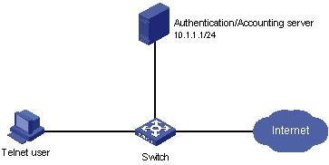
Figure 1-7 Remote RADIUS authentication of Telnet users
III. Configuration procedure
# Enter system view.
<H3C> system-view
[H3C]
# Adopt AAA authentication for Telnet users.
[H3C] user-interface vty 0 4
[H3C-ui-vty0-4] authentication-mode scheme
# Configure an ISP domain.
[H3C] domain cams
[H3C-isp-cams] access-limit enable 10
[H3C-isp-cams] quit
# Configure a RADIUS scheme.
[H3C] radius scheme cams
[H3C-radius-cams] accounting optional
[H3C-radius-cams] primary authentication 10.110.91.164 1812
[H3C-radius-cams] key authentication expert
[H3C-radius-cams] server-type extended
[H3C-radius-cams] user-name-format with-domain
[H3C-radius-cams] quit
# Associate the ISP domain with the RADIUS scheme.
[H3C] domain cams
[H3C-isp-cams] scheme radius-scheme cams
A Telnet user logging into the switch by a name in the format of userid @cams belongs to the cams domain and will be authenticated according to the configuration of the cams domain.
1.7.2 Local Authentication of FTP/Telnet Users
& Note:
The configuration procedure for the local authentication of FTP users is similar to that of Telnet users. The following description only takes the local authentication of Telnet users as example.
I. Network requirements
In the network environment shown in Figure 1-8, the switch needs to be configured so that the Telnet users logging into the switch are authenticated locally.
II. Network diagram
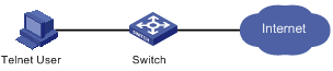
Figure 1-8 Local authentication of Telnet users
III. Configuration procedure
Method 1: Use a local authentication scheme.
# Enter system view.
<H3C> system-view
[H3C]
# Adopt AAA authentication for Telnet users.
[H3C] user-interface vty 0 4
[H3C-ui-vty0-4] authentication-mode scheme
[H3C-ui-vty0-4] quit
# Create and configure a local user named telnet.
[H3C] local-user telnet
[H3C-luser-telnet] service-type telnet
[H3C-luser-telnet] password simple secret
[H3C-luser-telnet] attribute idle-cut 300 access-limit 5
[H3C] domain system
[H3C-isp-system] scheme local
A Telnet user logging into the switch with the name telnet@system belongs to the domain system and will be authenticated according to the configuration of the domain system.
Method 2: Use a local RADIUS server.
This method is similar to the remote authentication method described in Remote RADIUS Authentication of Telnet/SSH Users. You only need to change the server IP address, the authentication password, and the UDP port number for authentication service in configuration step "Configure a RADIUS scheme" in Remote RADIUS Authentication of Telnet/SSH Users to 127.0.0.1, expert, and 1645 respectively, and configure local users (whether the name of local user carries domain name should be consistent with the configuration in RADIUS scheme).
1.7.3 TACACS Authentication, Authorization, and Accounting of Telnet Users
I. Network requirements
The switch needs to be configured so that the Telnet users logging in to the TACACS server are authenticated, authorized, and accounted.
A TACACS server with IP address 10.110.91.164 is connected to the switch. This server will be used as the AAA server. On the switch, set the shared key that is used to exchange packets with the AAA TACACS server as expert. Configure the switch to strip off the domain name in the user name to be sent to the TACACS server.
Configure the shared key as expert on the TACACS server for exchanging packets with the switch.
II. Network diagram
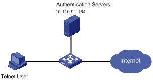
Figure 1-9 Remote TACACS authentication and authorization of Telnet users
III. Configuration procedure
# Add a Telnet user.
Omitted here
# Configure a HWTACACS scheme.
<H3C> system-view
[H3C] hwtacacs scheme hwtac
[H3C-hwtacacs-hwtac] primary accounting 10.110.91.164 49
[H3C-hwtacacs-hwtac] primary authentication 10.110.91.164 49
[H3C-hwtacacs-hwtac] primary authorization 10.110.91.164 49
[H3C-hwtacacs-hwtac] key accounting expert
[H3C-hwtacacs-hwtac] key authentication expert
[H3C-hwtacacs-hwtac] key authorization expert
[H3C-hwtacacs-hwtac] user-name-format without-domain
[H3C-hwtacacs-hwtac] quit
# Configure the HWTACACS scheme hwtac to be referenced by the domain.
[H3C] domain hwtacacs
[H3C-isp-hwtacacs] scheme hwtacacs-scheme hwtac
1.8 Troubleshooting AAA & RADIUS & HWTACACS Configuration
1.8.1 Troubleshooting the RADIUS Protocol
The RADIUS protocol is at the application layer in the TCP/IP protocol suite. This protocol prescribes how the switch and the RADIUS server of the ISP exchange user information with each other; therefore, it is likely that RADIUS configuration will become faulty.
Symptom 1: User authentication/authorization always fails.
Possible reasons and solutions:
l The entered user name is not in the userid@isp-name format, or no default ISP domain is specified on the switch — Use the correct user name format, or set a default ISP domain on the switch.
l The user is not configured in the database of the RADIUS server — Check the database of the RADIUS server; verify that the configuration information about the user exists.
l The user input an incorrect password — Verify that the correct password is input.
l The switch and the RADIUS server have different shared keys — Compare the shared keys at the two ends and verify that they are identical.
l The switch cannot communicate with the RADIUS server (you can determine by pinging the RADIUS server from the switch) — Take measures to make the switch communicate with the RADIUS server normally.
Symptom 2: RADIUS packets cannot be sent to the RADIUS server.
Possible reasons and solutions:
l The communication links (physical/link layer) between the switch and the RADIUS server is disconnected/blocked — Take measures to make the links connected/unblocked.
l None or incorrect RADIUS server IP address is set on the switch — Be sure to set a correct RADIUS server IP address.
l One or all AAA UDP port settings are incorrect — Be sure to set the same UDP port numbers as those on the RADIUS server.
Symptom 3: The user passes the authentication and gets authorized, but the accounting information cannot be transmitted to the RADIUS server.
Possible reasons and solutions:
l The accounting port number is not properly set — Be sure to set a correct port number for RADIUS accounting.
l The switch requests that both the authentication/authorization server and the accounting server use the same device (with the same IP address), but in fact they run on different devices — Be sure to configure the RADIUS servers on the switch according to the actual situation.
1.8.2 Troubleshooting the HWTACACS Protocol
Troubleshooting of HWTACACS configuration is similar to that of RADIUS configuration. See the previous section if you encounter an HWTACACS fault.
Chapter 2 EAD Configuration
When configuring EAD, go to these sections for information you are interested in:
l Typical Network Application of EAD
2.1 Introduction to EAD
Endpoint admission defense (EAD) is an attack defense solution that monitors endpoint admission. This enhances the active defense ability of endpoints, and prevents viruses and worms from spreading on the network. With the cooperation among security client, security policy server, access device, and antivirus software, EAD confines the endpoints that fail to comply with the security requirements to the quarantine area, thereby preventing hazardous terminals from compromising network security.
With EAD enabled, the switch determines the validity of session control packets it receives according to the source IP address of the packets. Only those session control packets sent from the authentication server and the security policy server can be regarded as valid.
Basic EAD functions are implemented through the cooperation among security client, security cooperation device (switch), security policy server, antivirus server, and patch server, as shown in Figure 2-1.
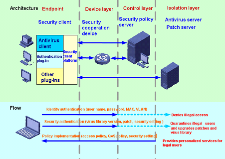
Figure 2-1 EAD basic principle
2.2 Typical Network Application of EAD
The EAD scheme checks the security status of the user, and implements the user access control policy forcibly according to the result. Therefore, those non-compliant users are isolated and are forced to upgrade virus database software and install system patches. Figure 2-2 shows the typical network application of EAD.
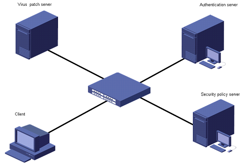
Figure 2-2 Typical network application of EAD
The security client (software installed on PC) checks the security status of a client that just passes the authentication, and interacts with the security policy server. If the client is not compliant with the security standard, the security policy server issues ACL control packets to the switch to control which resources the client can access.
After the client’s vulnerability is fixed and it is compliant with the required security standard, the security client passes the security state of the client to the security policy server, which then reissues an ACL to the switch to assign the access right to the client so that it can access more network resources.
2.3 EAD Configuration
2.3.1 Configuration prerequisites
EAD is implemented typically in RADIUS scheme. Before configuring EAD, perform the following configuration:
l Configuring the attributes, such as the user name, user type, and password for access users. If local authentication is to be performed, you need to configure these attributes on the switch; if remote authentication is to be performed, you need to configure these attributes on the AAA sever.
l Configuring a RADIUS scheme.
l Associating domain with RADIUS scheme.
For the detailed configuration procedure, refer to AAA & RADIUS & HWTACACS Configuration.
2.3.2 Configuring EAD
Table 2-1 EAD configuration
|
To do... |
Use the command... |
Remarks |
|
Enter system view |
system-view |
— |
|
Enter RADIUS scheme view |
radius scheme radius-scheme-name |
— |
|
Configure the RADIUS server type to extended |
server-type extended |
Optional By default, for a new RADIUS scheme, the server type is standard; The type of RADIUS server in the default RADIUS scheme system is extended. |
|
Configure the IP address for the security policy server |
security-policy-server ip-address |
Optional This configuration is optional if the security policy server and RADIUS server run on the same machine; otherwise, it is required. |
2.4 EAD Configuration Example
I. Network requirements
As shown in Figure 2-3:
l A user's workstation is connected to Ethernet 2/0/1 of the switch.
l The user's workstation adopts 802.1X client supporting EAD extended function.
l By configuring the switch, user remote authentication is implemented through RADIUS server and EAD control is achieved through security policy server.
The following are the configuration tasks:
l Connect the RADIUS authentication server to the switch. The IP address of the server is 10.110.91.164, and the switch adopts port 1812 to communicate with the authentication server.
l Configure the authentication server type as extended.
l Configure the encryption password for exchanging messages between the switch and RADIUS server as expert.
l Configure the IP address of the security policy server as 10.110.91.166.
II. Network diagram
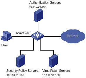
Figure 2-3 EAD configuration example
III. Configuration procedure
# Configure 802.1X on the switch. Refer to the 802.1X module in H3C S7500 Series Ethernet Switches Operation Manual for detailed description.
# Configure a domain.
<H3C> system-view
[H3C] domain system
[H3C-isp-system] quit
# Configure a RADIUS scheme.
[H3C] radius scheme cams
[H3C-radius-cams] primary authentication 10.110.91.164 1812
[H3C-radius-cams] key authentication expert
[H3C-radius-cams] accounting optional
[H3C-radius-cams] server-type extended
# Configure the IP address for the security policy server.
[H3C-radius-cams] security-policy-server 10.110.91.166
# Associate the domain with the RADIUS scheme.
[H3C-radius-cams] quit
[H3C] domain system
[H3C-isp-system] radius-scheme cams