- Table of Contents
-
- H3C S7500 Series Operation Manual(Release 3100 Series)-(V1.04)
- 00-1Cover
- 00-2Overview
- 01-CLI Configuration
- 02-Login Configuration
- 03-Configuration File Management Configuration
- 04-VLAN Configuration
- 05-Extended VLAN Application Configuration
- 06-IP Address-IP Performance-IPX Configuration
- 07-GVRP Configuration
- 08-QinQ Configuration
- 09-Port Basic Configuration
- 10-Link Aggregation Configuration
- 11-Port Isolation Configuration
- 12-Port Binding Configuration
- 13-DLDP Configuration
- 14-MAC Address Table Configuration
- 15-MSTP Configuration
- 16-Routing Protocol Configuration
- 17-Multicast Configuration
- 18-802.1x Configuration
- 19-AAA-RADIUS-HWTACACS-EAD Configuration
- 20-Traffic Accounting Configuration
- 21-VRRP-HA Configuration
- 22-ARP Configuration
- 23-DHCP Configuration
- 24-ACL Configuration
- 25-QoS Configuration
- 26-Mirroring Configuration
- 27-Cluster Configuration
- 28-PoE Configuration
- 29-UDP-Helper Configuration
- 30-SNMP-RMON Configuration
- 31-NTP Configuration
- 32-SSH Terminal Service Configuration
- 33-File System Management Configuration
- 34-FTP and TFTP Configuration
- 35-Information Center Configuration
- 36-DNS Configuration
- 37-System Maintenance and Debugging Configuration
- 38-HWPing Configuration
- 39-RRPP Configuration
- 40-NAT-Netstream-Policy Routing Configuration
- 41-Telnet Protection Configuration
- 42-Hardware-Dependent Software Configuration
- Related Documents
-
| Title | Size | Download |
|---|---|---|
| 11-Port Isolation Configuration | 72 KB |
Table of Contents
Chapter 1 Port Isolation Configuration
1.1.1 Introduction to Port Isolation
1.1.2 Port Isolation and Link Aggregation
1.2 Configuring Port Isolation
1.3 Displaying Port Isolation Configuration
1.4 Port Isolation Configuration Example
Chapter 1 Port Isolation Configuration
When configuring port isolation, go to these sections for information you are interested in:
l Displaying Port Isolation Configuration
l Port Isolation Configuration Example
1.1 Port Isolation Overview
1.1.1 Introduction to Port Isolation
Through the port isolation feature, you can add the ports to be controlled into an isolation group to isolate Layer 2 and Layer 3 data between ports in the isolation group. Thus, it can improve network security and deliver flexible networking solutions.
Currently, you can configure 64 isolation groups on a switch. The number of Ethernet ports an isolation group can accommodate is not limited.
& Note:
l An isolation group only isolates the member ports in it.
l The port isolation function is independent of VLAN configuration.
1.1.2 Port Isolation and Link Aggregation
l When a port in an aggregation group joins an isolation group, the other ports in the aggregation group join the isolation group automatically.
l When a port in an aggregation group leaves an isolation group, the other ports in the aggregation group leave the isolation group automatically.
1.2 Configuring Port Isolation
Follow these steps to configure port isolation:
|
To do… |
Use the command… |
Remarks |
|
Enter system view |
system-view |
— |
|
Create an isolation group |
port-isolate group group-id |
Required |
|
Specify a description string for the current isolation group |
description text |
Optional |
|
Add the specified port into the isolation group |
port interface-list |
Optional By default, an isolation group contains no Ethernet port. |
|
Enter Ethernet port view |
interface interface-type interface-number |
— |
|
Add the current Ethernet port to the specified isolation group |
port isolate group group-id |
Optional By default, an isolation group contains no Ethernet port. |
& Note:
l An Ethernet port belongs to only one port isolation group. If you add an Ethernet port to different isolation groups, the port belongs to only the latest isolation group to which the port is added.
l Currently, cards of Type A (LS81FT48A, LS81FM24A, LS81FS24A, LS81GB8UA, and LS81GT8UA) do not support the Port Isolation feature.
1.3 Displaying Port Isolation Configuration
|
To do… |
Use the command… |
Remarks |
|
Display the configuration of the created isolation group |
display isolate port [ group group-id ] |
Available in any view. |
1.4 Port Isolation Configuration Example
I. Network requirements
l PC 2, PC 3 and PC 4 connect to the switch ports Ethernet 2/0/2, Ethernet 2/0/3, and Ethernet 2/0/4 respectively.
l It is desired that PC 2, PC 3 and PC 4 are isolated from each other so that they cannot communicate with each other.
II. Network diagram
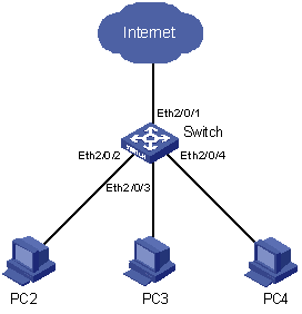
Figure 1-1 Network diagram for port isolation configuration
III. Configuration procedure
# Create isolation group 1.
<H3C> system-view
System View: return to User View with Ctrl+Z.
[H3C] port-isolate group 1
# Add Ethernet 2/0/2, Ethernet 2/0/3, and Ethernet 2/0/4 to the isolation group 1.
[H3C-port-isolate-group1] port Ethernet2/0/2 to Ethernet2/0/4
# Display information about the ports in the isolation group.
[H3C-port-isolate-group1] display isolate port
Isolate group ID: 1
Isolated port(s) in group 1:
Ethernet2/0/2 Ethernet2/0/3 Ethernet2/0/4