- Table of Contents
-
- H3C S7500 Series Operation Manual(Release 3100 Series)-(V1.04)
- 00-1Cover
- 00-2Overview
- 01-CLI Configuration
- 02-Login Configuration
- 03-Configuration File Management Configuration
- 04-VLAN Configuration
- 05-Extended VLAN Application Configuration
- 06-IP Address-IP Performance-IPX Configuration
- 07-GVRP Configuration
- 08-QinQ Configuration
- 09-Port Basic Configuration
- 10-Link Aggregation Configuration
- 11-Port Isolation Configuration
- 12-Port Binding Configuration
- 13-DLDP Configuration
- 14-MAC Address Table Configuration
- 15-MSTP Configuration
- 16-Routing Protocol Configuration
- 17-Multicast Configuration
- 18-802.1x Configuration
- 19-AAA-RADIUS-HWTACACS-EAD Configuration
- 20-Traffic Accounting Configuration
- 21-VRRP-HA Configuration
- 22-ARP Configuration
- 23-DHCP Configuration
- 24-ACL Configuration
- 25-QoS Configuration
- 26-Mirroring Configuration
- 27-Cluster Configuration
- 28-PoE Configuration
- 29-UDP-Helper Configuration
- 30-SNMP-RMON Configuration
- 31-NTP Configuration
- 32-SSH Terminal Service Configuration
- 33-File System Management Configuration
- 34-FTP and TFTP Configuration
- 35-Information Center Configuration
- 36-DNS Configuration
- 37-System Maintenance and Debugging Configuration
- 38-HWPing Configuration
- 39-RRPP Configuration
- 40-NAT-Netstream-Policy Routing Configuration
- 41-Telnet Protection Configuration
- 42-Hardware-Dependent Software Configuration
- Related Documents
-
| Title | Size | Download |
|---|---|---|
| 27-Cluster Configuration | 241 KB |
Table of Contents
1.1.5 Switch Roles in the Cluster
1.2 Management Device Configuration
1.2.1 Management Device Configuration Task List
1.2.2 Enabling NDP Globally and for Specific Ports
1.2.3 Configuring NDP-Related Parameters
1.2.4 Enabling NTDP Globally and for Specific Ports
1.2.5 Configuring NTDP-Related Parameters
1.2.6 Enabling the Cluster Function
1.2.7 Configuring Cluster Parameters
1.2.8 Configuring Interaction for the Cluster
1.3 Member Device Configuration
1.3.1 Member Device Configuration Task List
1.3.2 Enabling NDP Globally and for Specific Ports
1.3.3 Enabling NTDP Globally and for Specific Ports
1.3.4 Configure Member Devices to Access FTP/TFTP Server of the Cluster
1.4 Intra-Cluster Configuration
1.5 Displaying and Maintaining a Cluster
1.6 Cluster Configuration Example
1.6.1 Cluster Configuration Example
Chapter 1 Cluster
When configuring cluster, go to these sections for information you are interested in:
l Management Device Configuration
l Displaying and Maintaining a Cluster
l Cluster Configuration Example
1.1 Cluster Overview
1.1.1 Introduction to HGMP V2
A cluster is implemented through Huawei group management protocol (HGMP V2). By employing HGMP V2, a network administrator can manage multiple switches using the public IP address of a switch known as a management device. The switches under the management are member devices. The management device, along with the member devices, forms a cluster. Normally, a public IP address is not assigned to a member device. Management and maintenance operations intended for the member devices in a cluster are redirected by the management device. Figure 1-1 illustrates a typical cluster implementation.
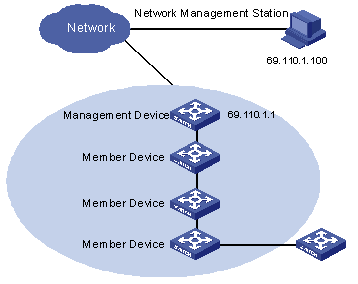
Figure 1-1 Diagram for cluster
HGMP V2 offers the following advantages:
l Simplifying the procedures to configure multiple switches. After assigning a public IP address to the management device, you can configure/manage a specific member device on the management device instead of logging in to it in advance.
l Functions of topology discovery and display, which assist network monitoring and debugging
l Software upgrading and parameter configuring can be performed simultaneously on multiple switches.
l Free of topology and distance limitations
l Saving IP address resource
HGMP V2 is comprised of the following three protocols:
l Neighbor Discovery Protocol (NDP): HGMP V2 implements NDP to discover the information about the directly connected neighbor devices, including device type, software/hardware version, connecting port and so on. The information including device ID, port mode (duplex or half duplex), product version, and Boot ROM version can also be given.
l Neighbor Topology Discovery Protocol (NTDP): HGMP V2 implements NTDP to collect the information about the network topology, including the device connections and the device information in the network. The hop range for topology discovery can be adjusted manually.
l Cluster management protocol: The cluster management protocol provides the member recognition and member management function. It can also perform large-scaled device management together with the network administrator. Member recognition means that the management device recognizes each member in the cluster through locating each member and then distributes the configuration and management commands to the members. Member management means to manage the following events through the management device, including adding a member, removing a member, and the member’s authentication on the management device. Member management also manages the cluster parameters including interval of sending handshake packets, management VLAN of the cluster, public FTP server of the cluster.
Cluster-related configurations are described in the following sections.
1.1.2 Introduction to NDP
NDP is the protocol for discovering the information about the adjacent nodes. NDP operates on the data link layer, so it supports different network layer protocols.
NDP is used to discover the information about directly connected neighbors, including the device type, software/hardware version, and connecting port of the adjacent devices. It can also provide the information concerning device ID, port simplex/duplex status, product version, and Boot ROM version.
An NDP-enabled device maintains an NDP information table. Each entry in an NDP table ages with time. You can also clear the current NDP information manually to have adjacent information collected again.
An NDP-enabled device broadcasts NDP packets regularly to all active ports. An NDP packet carries the holdtime field, which indicates the period for the receiving devices to keep the NDP data. Receiving devices store only the information carried in the received NDP packets rather than forward them. The corresponding data entry in the NDP table is updated when the received information is different from the existing one. Otherwise, only the holdtime of the corresponding entry is updated.
1.1.3 Introduction to NTDP
NTDP is a protocol for network topology information collection. NTDP provides the information about the devices that can be added to clusters and collects the topology information within the specified hops for cluster management.
Based on the NDP information table created by NDP, NTDP transmits and forwards NTDP topology collection requests to collect the NDP information and neighboring connection information of each device in a specific network range for the management device or the network administrator to implement required functions.
Upon detecting a change occurred on a neighbor, a member device informs the management device of the change through handshake packets. The management device then collects the specified topology information through NTDP. Such a mechanism enables topology changes to be tracked in time.
& Note:
As for NTDP implementing, you need to perform configurations on the management device, the member devices, and the candidate devices as follows:
l On the management device, enable NTDP both globally and for specific ports, and configure the NTDP settings.
l On each member device and candidate device, enable NTDP both globally and for specific ports. As member devices and candidate devices adopt the NTDP settings configured for the management device, NTDP setting configurations are not needed.
l NTDP takes effect in the management VLAN only. S7500 series Ethernet switches take VLAN 1 as the management VLAN, that is, the NTDP function of the S7500 series takes effect in VLAN 1 only.
1.1.4 Introduction to Cluster
I. Introduction to cluster configuration
A cluster has one (and only one) management device. Note the following points when creating a cluster:
l You need to designate a management device first. The management device of a cluster is the portal of the cluster. That is, any operations performed in external networks and intended for the member devices of a cluster, such as accessing, configuring, managing, and monitoring, can only be implemented through the management device.
l The management device of a cluster recognizes and controls all the member devices in the cluster, no matter where they are located in the network or how they are connected.
l The management device collects topology information about all the member and candidate devices to provide useful information for users to establish a cluster.
l The management device manages and monitors the devices in the cluster by collecting and processing NDP/NTDP packets. NDP/NTDP packets contain network topology information.
All the above-mentioned operations need the support of the cluster function.
& Note:
You need to enable the cluster function and configure cluster parameters on a management device. However, you only need to enable the cluster function on the member devices and candidate devices.
II. Introduction to function of cluster
Cluster provides the function of batch management for the switches in the network. It provides external management and maintenance applications, including SNMP, command line, program and data loading, log reporting and alarm reporting. These applications can be divided into internal-to-external applications and external-to-internal applications. All the applications are processed according to the following procedures:
l The communication between the management device and member device in the cluster is implemented through packet interaction in the management VLAN.
l The communication between the cluster and the external server is implemented by the Layer 3 interface of the cluster management VLAN.
l When the member device in the cluster communicates with the external server, the member device transmits the data to the management device first, and then the management device transmits the data to the external server. When the management program running on the external server manages the member device, the external server transmits the protocol packets to the management device first, and then the management device forwards the protocol packets to the member device.
You can configure public FTP servers, TFTP servers, logging hosts and SNMP hosts for the whole cluster. The management device in the cluster is the default public FTP server of the cluster when the public FTP server of the cluster is not configured. Cluster, together with the network management system, can perform large-scaled device management.
& Note:
The S7500 series manage the cluster with VLAN 1, which serves as the management VLAN in the cluster. You are required to configure the IP address of the Layer 3 virtual interface of the management VLAN before setting up a cluster. Otherwise, the cluster cannot be set up successfully. After the cluster is set up, you are not allowed to modify the IP address of the management VLAN interface.
1.1.5 Switch Roles in the Cluster
According to their functions and status in a cluster, switches in the cluster play different roles. You can specify the role a switch plays. A switch also changes its role according to specific rules.
The following three switch roles exist in a cluster: management device, member device, and candidate device.
Table 1-1 Switch roles in the cluster
|
Role |
Configuration |
Description |
|
Management device |
l Configured with a public IP address. l Receive management commands that a user sends through the public network and process the received commands |
l Provide management interfaces for all switches in the cluster l Manage member devices by redirecting commands, that is, forward the commands to the intended member devices for processing l Provide the following functions, including neighbor discovery, topology information collection, cluster management, and cluster state maintenance, and support all types of FTP servers and SNMP host proxies |
|
Member device |
Normally, a member device is not configured with a public IP address |
l Member in the cluster l Neighbor discovery, being managed by the management device, running commands forwarded by proxies, and failure/log reporting |
|
Candidate device |
Normally, a candidate device is not configured with a public IP address |
A candidate device is a switch that does not belong to any cluster, although it can be added to a cluster |
The switch roles are switched according to the following rules:
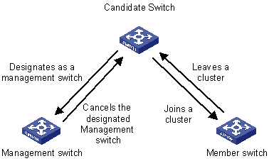
Figure 1-2 Role switching roles
l Each cluster has one (and only one) management device. A management device collects NDP/NTDP information to discover and determine candidate devices, which can be then added into the cluster through manual configurations.
l A candidate device becomes a member device after being added to a cluster.
l A member device becomes a candidate device after being removed from the cluster.
1.2 Management Device Configuration
1.2.1 Management Device Configuration Task List
Complete the following tasks to configure the management device:
|
Task |
Remarks |
|
Required |
|
|
Required |
|
|
Required |
|
|
Required |
|
|
Required |
|
|
Required |
|
|
Required |
1.2.2 Enabling NDP Globally and for Specific Ports
Follow these steps to enable NDP globally and for a specific port:
|
To do… |
Use the command… |
Remarks |
||
|
Enter system view |
system-view |
— |
||
|
Enable NDP globally |
ndp enable |
Required By default, NDP is enabled globally |
||
|
Enable NDP for the specified Ethernet ports |
In system view |
ndp enable interface port-list |
You must choose one of them By default, NDP is enabled on the port |
|
|
In Ethernet port view |
Enter Ethernet port view |
interface interface-type interface-number |
||
|
Enable NDP on the port |
ndp enable |
|||
1.2.3 Configuring NDP-Related Parameters
Follow these steps to configure NDP-related parameters:
|
To do… |
Use the command… |
Remarks |
|
Enter system view |
system-view |
— |
|
Configure the holdtime of NDP information |
ndp timer aging aging-in-seconds |
Optional By default, the aging time of NDP packets is 180 seconds |
|
Configure the interval to send NDP packets |
ndp timer hello seconds |
Optional By default, the interval of sending NDP packets is 60 seconds |
1.2.4 Enabling NTDP Globally and for Specific Ports
Follow these steps to enable NTDP globally and for specific ports:
|
To do… |
Use the command… |
Remarks |
|
Enter system view |
system-view |
— |
|
Enable NTDP globally |
ntdp enable |
Required |
|
Enter Ethernet port view |
interface interface-type interface-number |
— |
|
Enable NTDP for the Ethernet port |
ntdp enable |
Required |
1.2.5 Configuring NTDP-Related Parameters
Follow these steps to configure NTDP parameters:
|
To do… |
Use the command… |
Remarks |
|
Enter system view |
system-view |
— |
|
Configure the range within which topology information is to be collected |
ntdp hop hop-value |
Optional By default, the hop range for topology collection is three hops |
|
Configure the hop delay to forward topology-collection requests |
ntdp timer hop-delay time |
Optional By default, the delay of the device is 200 ms |
|
Configure the port delay to forward topology collection requests |
ntdp timer port-delay time |
Optional By default, the port delay is 20 ms |
|
Configure the interval to collect topology information |
ntdp timer interval-in-minutes |
Optional By default, the interval of topology collection is 0. |
|
Quit system view |
quit |
— |
|
Start topology information collection |
ntdp explore |
Optional |
1.2.6 Enabling the Cluster Function
Follow these steps to enable the cluster function:
|
To do… |
Use the command… |
Remarks |
|
Enter system view |
system-view |
— |
|
Enable the cluster function globally |
cluster enable |
Optional By default, the cluster function is enabled |
1.2.7 Configuring Cluster Parameters
I. Creating a cluster and configuring cluster parameters manually
Follow these steps to configure cluster parameters manually:
|
To do… |
Use the command… |
Remarks |
|
Enter system view |
system-view |
— |
|
Enter VLAN interface view |
interface Vlan-interface vlan-id |
Required You are required to configure the IP address of the Layer 3 virtual interface of VLAN 1 before you set up a cluster. Otherwise, the cluster cannot be set up. |
|
Configure the IP address of the VLAN interface |
ip address ip-address { mask | mask-length } |
Required |
|
Enter cluster view |
cluster |
— |
|
Configure an IP address pool for the cluster |
ip-pool administrator-ip-address { ip-mask | ip-mask-length } |
Required |
|
Build a cluster |
build name |
Optional The name argument indicates the name to be assigned. |
|
Configure the holdtime for a switch |
holdtime seconds |
Optional By default, the holdtime is 60 seconds |
|
Set the interval to send handshake packets |
timer interval |
Optional By default, the interval to send handshake packets is 10 seconds |
|
Quit cluster view |
quit |
— |
II. Building a cluster automatically
Follow these steps to enable the cluster function automatically:
|
To do… |
Use the command… |
Remarks |
|
Enter system view |
system-view |
— |
|
Enter VLAN interface view |
interface Vlan-interface vlan-id |
Required You are required to configure the IP address of the Layer 3 virtual interface of VLAN 1 before you set up a cluster. Otherwise, the cluster cannot be set up. |
|
Configure the IP address of the VLAN interface |
ip address ip-address { mask | mask-length } |
Required |
|
Enter cluster view |
cluster |
— |
|
Configure the rang e of the IP addresses of the cluster |
ip-pool administrator-ip-address { ip-mask | ip-mask-length } |
Required |
|
Build a cluster automatically |
auto-build [ recover ] |
Optional You can build clusters according to corresponding prompts |
& Note:
l After a cluster is built automatically, ACL 3998 and ACL 3999 will be generated automatically.
l After a cluster is built automatically, ACL 3998 and ACL 3999 can neither be configured/modified nor removed.
1.2.8 Configuring Interaction for the Cluster
Follow these steps to configure interaction for the cluster:
|
To do… |
Use the command… |
Remarks |
|
Enter system view |
system-view |
— |
|
Enter cluster view |
cluster |
Required |
|
Configure the public FTP server for the cluster |
ftp-server ip-address |
Optional |
|
Configure the TFTP server for the cluster |
tftp-server ip-address |
Optional |
|
Configure the logging host for the cluster |
logging-host ip-address |
Optional |
|
Configure the SNMP host for the cluster |
snmp-host ip-address |
Optional |
1.3 Member Device Configuration
1.3.1 Member Device Configuration Task List
Complete the following tasks to configure a member device:
|
Task |
Remarks |
|
Required |
|
|
Required |
|
|
Configure Member Devices to Access FTP/TFTP Server of the Cluster |
Required |
1.3.2 Enabling NDP Globally and for Specific Ports
Follow these steps to enable NDP globally and for specific ports:
|
To do… |
Use the command… |
Remarks |
||
|
Enter system view |
system-view |
— |
||
|
Enable NDP globally |
ndp enable |
Required |
||
|
Enable NDP for specified ports |
In system view |
ndp enable interface port-list |
Required You can choose to enable NDP in system view or in Ethernet port view |
|
|
In Ethernet port view |
Enter Ethernet port view |
interface interface-type interface-number |
||
|
Enable NDP on the port |
ndp enable |
|||
1.3.3 Enabling NTDP Globally and for Specific Ports
Follow these steps to enable NTDP globally and for specific ports:
|
To do… |
Use the command… |
Remarks |
|
Enter system view |
system-view |
— |
|
Enable NTDP globally |
ntdp enable |
Required |
|
Enter Ethernet port view |
interface interface-type interface-number |
— |
|
Enable NTDP for the port |
ntdp enable |
Required |
1.3.4 Configure Member Devices to Access FTP/TFTP Server of the Cluster
Perform the following configuration on a member device:
|
To do… |
Use the command… |
Remarks |
|
Access the public FTP server of the cluster |
ftp cluster |
Optional Available in user view |
|
Download files from the public TFTP server of the cluster |
tftp cluster get source-file [ destination-file ] |
Optional Available in user view |
|
Upload files to the public TFTP server of the cluster |
tftp cluster put source-file [ destination-file ] |
Optional Available in user view |
1.4 Intra-Cluster Configuration
Follow these steps to configure a cluster:
|
To do… |
Use the command… |
Remarks |
|
Enter system view |
system-view |
— |
|
Enter cluster view |
cluster |
— |
|
Add a candidate device to a cluster |
add-member [ member-number ] mac-address H-H-H [ password password ] |
Optional |
|
Remove a member device from the cluster |
delete-member member-number |
Optional |
|
Reboot a specified member device |
reboot member { member-number | mac-address H-H-H } [ eraseflash ] |
Optional |
|
Return to system view |
quit |
— |
|
Return to user view |
quit |
— |
|
Switch between the management device view and a member device view |
cluster switch-to { member-number | mac-address H-H-H | administrator } |
Optional Switch between the management device view and the member device view |
1.5 Displaying and Maintaining a Cluster
|
To do… |
Use the command… |
Remarks |
|
Display the global NDP configuration (including the interval to send NDP packets and the holdtime) |
display ndp |
Optional Available in any view |
|
Display the information about the neighbors discovered by NDP and connected to specified ports |
display ndp interface port-list |
|
|
Display the global NTDP information |
display ntdp |
|
|
Display device information collected through NTDP |
display ntdp device-list [ verbose ] |
|
|
Display state and statistics information about a cluster |
display cluster |
|
|
Display the information about the candidate devices of a cluster |
display cluster candidates [ mac-address H-H-H | verbose ] |
|
|
Display the information about the cluster members |
display cluster members [ member-number | verbose ] |
|
|
Clear the NDP statistics on a port |
reset ndp statistics [ interface port-list ] |
— |
1.6 Cluster Configuration Example
1.6.1 Cluster Configuration Example
I. Network requirements
Three switches form a cluster, in which:
l The management device is an S7500 switch.
l The rest are member devices.
The S7500 switch manages other two member devices as the management device. The detailed information about the cluster is as follows.
l The two member devices are connected to GigabitEthernet 2/0/2 and GigabitEthernet 2/0/3 of the management device.
l The management device is connected to the external network through GigabitEthernet 2/0/1.
l GigabitEthernet 2/0/1 belongs to VLAN 1, whose interface IP address is 163.172.55.1.
l All the devices in the cluster use the same FTP server and TFTP server.
l The FTP server and TFTP server share one IP address: 63.172.55.1.
l The SNMP site and log host share one IP address: 69.172.55.4.
II. Network diagram
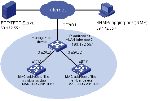
Figure 1-3 Network diagram for HGMP cluster configuration
III. Configuration procedure
1) Configure the member devices (taking one member as an example)
# Enable NDP globally and for Ethernet 1/1.
<H3C> system-view
[H3C] ndp enable
[H3C] interface Ethernet 1/1
[H3C-Ethernet1/1] ndp enable
[H3C-Ethernet1/1] quit
# Enable NTDP globally and for Ethernet 1/1.
[H3C] ntdp enable
[H3C] interface Ethernet 1/1
[H3C-Ethernet1/1] ntdp enable
[H3C-Ethernet1/1] quit
# Enable the cluster function.
[H3C] cluster enable
2) Configure the management device
# Configure the IP address of the management VLAN (the S7500 series take VLAN 1 as the default VLAN).
<H3C> system-view
[H3C] interface Vlan-interface 1
[H3C-Vlan-interface1] ip address 163.172.55.1
[H3C-Vlan-interface1] quit
# Enable NDP globally and on ports GE 2/0/2 and GE 2/0/3.
[H3C] ndp enable
[H3C] interface GigabitEthernet 2/0/2
[H3C-GigabitEthernet2/0/2] ndp enable
[H3C-GigabitEthernet2/0/2] interface GigabitEthernet 2/0/3
[H3C-GigabitEthernet2/0/3] ndp enable
[H3C-GigabitEthernet2/0/3] quit
# Configure the holdtime of NDP information to be 200 seconds.
[H3C] ndp timer aging 200
# Configure the interval to send NDP packets to be 70 seconds.
[H3C] ndp timer hello 70
# Enable NTDP globally and for GE 2/0/2 and GE 2/0/3.
[H3C] ntdp enable
[H3C] interface GigabitEthernet 2/0/2
[H3C-GigabitEthernet1/0/2] ntdp enable
[H3C-GigabitEthernet1/0/2] interface GigabitEthernet 2/0/3
[H3C-GigabitEthernet1/0/3] ntdp enable
[H3C-GigabitEthernet1/0/3] quit
# Configure the hop count to collect topology to be 2.
[H3C] ntdp hop 2
# Configure the delay time for topology-collection requests to be forwarded on member devices to be 150 ms.
[H3C] ntdp timer hop-delay 150
# Configure the delay time for topology-collection requests to be forwarded through the ports of member devices to be 15 ms.
[H3C] ntdp timer port-delay 15
# Configure the interval to collect topology information to be 3 minutes.
[H3C] ntdp timer 3
# Enable the cluster function.
[H3C] cluster enable
# Enter cluster view.
[H3C] cluster
[H3C-cluster]
# Configure an IP address pool for the cluster. The IP address pool contains eight IP addresses, starting from 172.16.0.1.
[H3C-cluster] ip-pool 172.16.0.1 255.255.255.248
# Specify a name for the cluster and create the cluster.
[H3C-cluster] build aaa
[aaa_0.H3C-cluster]
# Add the attached two switches to the cluster.
[aaa_0.H3C-cluster] add-member 1 mac-address 00e0-fc01-0011
[aaa_0.H3C-cluster] add-member 17 mac-address 00e0-fc01-0012
# Configure the holdtime of the member device information to be 100 seconds.
[aaa_0.H3C-cluster] holdtime 100
# Configure the interval to send handshake packets to be 10 seconds.
[aaa_0.H3C-cluster] timer 10
# Configure the FTP Server, TFTP Server, Log host and SNMP host for the cluster.
[aaa_0.H3C-cluster] ftp-server 63.172.55.1
[aaa_0.H3C-cluster] tftp-server 63.172.55.1
[aaa_0.H3C-cluster] logging-host 69.172.55.4
[aaa_0.H3C-cluster] snmp-host 69.172.55.4
3) Configure the member devices (taking one member as an example)
Add the devices connected to the management device into the cluster and perform the following configuration on the member device.
# Connect the member device to the public remote FTP server of the cluster.
<aaa_1.H3C> ftp cluster
# Download the file named aaa.txt from the public TFTP server to the member device.
<aaa_1.H3C> tftp cluster get aaa.txt
# Upload the file named bbb.txt from the member device to the public TFTP server of the cluster.
<aaa_1.H3C> tftp cluster put bbb.txt
& Note:
l Upon the completion of the above configurations, you can execute the cluster switch-to { member-number | mac-address H-H-H } command on the management device to switch to member device view to maintain and manage a member device. You can then execute the cluster switch-to administrator command to resume the management device view.
l You can also reboot a member device by executing the reboot member { member-number | mac-address H-H-H } [ eraseflash ] command on the management device. For detailed information about these configurations, refer to the preceding description in this chapter.
l After the configuration above, on the SNMP host you can receive logs and SNMP trap messages of all the cluster members.