- Table of Contents
-
- 04-Comware 7 CLI-based configuration examples (AC+fit AP deployment)
- 001-HTTPS Login Configuration Examples
- 002-SSH Configuration Examples
- 003-License Management Configuration Examples
- 004-AP Association with the AC at Layer 2 Configuration Examples
- 005-AP Association with the AC at Layer 2 (IPv6) Configuration Examples
- 006-Auto AP Configuration Examples
- 007-AP Association with the AC at Layer 3 Configuration Examples
- 008-AP Association with the AC at Layer 3 (IPv6) Configuration Examples
- 009-WEP Encryption Configuration Examples
- 010-PSK Encryption Configuration Examples
- 011-WPA3-SAE PSK Encryption Configuration Examples
- 012-WLAN Access (IPv6) Configuration Examples
- 013-Policy-Based Forwarding with Dual Gateways Configuration Examples
- 014-Scheduled Configuration Deployment by AP Group Configuration Examples
- 015-Inter-AC Roaming with Static Client VLAN Allocation Configuration Examples
- 016-Service Template and Radio Binding Configuration Examples
- 017-Scheduled WLAN Access Services Configuration Examples
- 018-HTTPS-Based Local Portal Authentication Configuration Examples
- 019-Remote Portal Authentication Configuration Examples
- 020-Local Portal Authentication through LDAP Server Configuration Examples
- 021-Local Portal Auth and SSID-based Auth Page Pushing Configuration Examples
- 022-Local Portal MAC-Trigger Authentication Configuration Examples
- 023-Portal MAC-Trigger Authentication Configuration Examples
- 024-Local Forwarding Mode and Local Portal MAC-Trigger Auth Configuration Examples
- 025-Local Portal Authentication (IPv6) Configuration Examples
- 026-Local Portal Authentication through LDAP Server (IPv6) Configuration Examples
- 027-Remote Portal Authentication (IPv6) Configuration Examples
- 028-Portal MAC-Trigger Authentication (IPv6) Configuration Example
- 029-Remote Portal Authentication with User Profile Authorization Configuration Examples
- 030-WiFiDog Portal Authentication Configuration Examples
- 031-Portal Fail-Permit Configuration Examples
- 032-Local MAC Authentication Configuration Examples
- 033-Remote MAC Authentication Configuration Examples
- 034-Local Portal Authentication Configuration Examples
- 035-Transparent Auth Through Remote MAC and Portal Auth Configuration Examples
- 036-Remote AP, Remote Portal, and MAC-Trigger Authentication Configuration Examples
- 037-MAC Authentication with Guest VLAN Assignment Configuration Examples
- 038-MAC Authentication with Guest VLAN Assignment (IPv6) Configuration Examples
- 039-Local MAC-And-802.1X Authentication Configuration Examples
- 040-Local 802.1X Authentication Configuration Examples
- 041-Local RADIUS-Based 802.1X Authentication in EAP Relay Mode Configuration Examples
- 042-Remote 802.1X Authentication Configuration Examples
- 043-Remote 802.1X Authentication (IPv6) Configuration Examples
- 044-Remote 802.1X Authentication in WPA3-Enterprise Mode Configuration Examples
- 045-802.1X Auth with ACL Assignment Through IMC Server Configuration Examples
- 046-802.1X Auth with User Profile Assignment Through IMC Server Configuration Examples
- 047-EAD Authentication Configuration Examples
- 048-EAD Authentication (IPv6) Configuration Examples
- 049-Local Forwarding Mode and Local Portal Authentication Configuration Examples
- 050-Local Forwarding Mode Direct Portal Authentication Configuration Examples
- 051-Local Forwarding Mode Direct Portal Authentication (IPv6) Configuration Examples
- 052-Local Forwarding Configuration Examples
- 053-Wired Port Local Forwarding through Wireless Terminator Configuration Examples
- 054-Remote AP Configuration Examples
- 055-Downlink VLAN Management for Fit-Mode APs Configuration Examples
- 056-Downlink VLAN Management for Fit APs and Cloud APs Configuration Examples
- 057-WIPS Configuration Examples
- 058-WIPS Countermeasures Against All SSIDs Configuration Examples
- 059-IP Source Guard (IPv4) Configuration Examples
- 060-IP Source Guard (IPv6) Configuration Examples
- 061-IPS Configuration Examples
- 062-URL Filtering Configuration Examples
- 063-Anti-Virus Configuration Examples
- 064-Data Filtering Configuration Examples
- 065-File Filtering Configuration Examples
- 066-Application Audit and Management Configuration Examples
- 067-Application Rate Limiting Configuration Examples
- 068-IRF Setup with LACP MAD Configuration Examples
- 069-IRF Setup with ARP MAD Configuration Examples
- 070-IRF Setup with Members Not Directly Connected Configuration Examples
- 071-IRF Setup with Members in One Chassis Configuration Examples
- 072-IRF Setup with Members in Different Chassis Configuration Examples
- 073-Dual-Link Backup Configuration Examples
- 074-Remote 802.1X Auth on an AC Hierarchy Network with Dual-Link Backup Configuration Examples
- 075-Remote Portal Auth on an AC Hierarchy Network with Dual-Link Backup Configuration Examples
- 076-OAuth-Based Portal MAC-Trigger Auth on a Local-Forwarding Dual-Link Backup Configuration Examples
- 077-Dual-Link Backup OAuth-Based Portal Authentication in Local Forwarding Configuration Examples
- 078-Dual-Link Backup Remote Portal MAC-Trigger Authentication in Local Forwarding Configuration Examples
- 079-Dual-Link Backup Remote Portal and Transparent MAC Auth in Local Forwarding Configuration Examples
- 080-Dual-Link Backup Remote Portal Authentication in Local Forwarding Configuration Examples
- 081-Dual-Link Backup Remote Portal and Transparent MAC Auth in Centralized Forwarding Configuration Examples
- 082-Dual-Link Backup Remote Portal Authentication in Centralized Forwarding Configuration Examples
- 083-Dual-Link Backup Lightweight Portal Authentication in Centralized Forwarding Configuration Examples
- 084-Dual-Link Backup OAuth-Based Portal Authentication in Centralized Forwarding Configuration Examples
- 085-Dual-Link Backup Remote Portal MAC-Trigger Auth in Centralized Forwarding Configuration Examples
- 086-Remote 802.1X Authentication on a Dual-Link AC Backup Network Configuration Examples
- 087-Remote MAC Authentication on a Dual-Link AC Backup Network Configuration Examples
- 088-AC Hierarchy Configuration Examples
- 089-Remote 802.1X Auth (Local AC Auth+AC Forwardering) Configuration Examples
- 090-Remote 802.1X Auth (Central AC Auth+AP Forwarding) Configuration Examples
- 091-AC Hierarchy (IPv6) Configuration Examples
- 092-WLAN Probe Configuration Examples
- 093-Multicast Optimization Configuration Examples
- 094-Client Rate Limiting Configuration Examples
- 095-Inter-AC Roaming Configuration Examples
- 096-Inter-AC Roaming (IPv6) Configuration Examples
- 097-Inter-AC Roaming in Local Forwarding Mode Configuration Examples
- 098-H3C Access Controllers Cooperative Roaming for 802.11v Clients Configuration Examples
- 099-WLAN Load Balancing Configuration Examples
- 100-Static Blacklist Configuration Examples
- 101-Client Quantity Control Configuration Examples
- 102-AP License Synchronization Configuration Examples
- 103-BLE Module iBeacon Transmission Configuration Examples
- 104-Medical RFID Tag Management Configuration Examples
- 105-iBeacon Management Configuration Examples
- 106-Mesh Link Establishment Between Fit APs Configuration Examples
- 107-Mesh Link Establishment Between a Fit AP and a Fat AP Configuration Examples
- 108-Auto-DFS and Auto-TPC Configuration Examples
- 109-AP Image Downloading Configuration Examples
- 110-Dual-Uplink Interfaces Configuration Guide
- 111-H3C Comware AC Cloud-Managed AP Centralized Management Configuration Examples
- 112-Internal-to-External Access Through NAT Configuration Examples
- 113-Layer 2 Static Aggregation Configuration Examples
- 114-Layer 2 Multicast Configuration Examples
- 115-Static VLAN Allocation Configuration Examples
- 116-URL Redirection Configuration Examples
- 117-IPv6 URL Redirection Configuration Examples
- Related Documents
-
| Title | Size | Download |
|---|---|---|
| 061-IPS Configuration Examples | 95.87 KB |
|
|
|
H3C Access Controllers |
|
IPS Configuration Examples |
|
|
Copyright © 2024 New H3C Technologies Co., Ltd. All rights reserved.
No part of this manual may be reproduced or transmitted in any form or by any means without prior written consent of New H3C Technologies Co., Ltd.
Except for the trademarks of New H3C Technologies Co., Ltd., any trademarks that may be mentioned in this document are the property of their respective owners.
The information in this document is subject to change without notice.
Contents
Introduction
The following information provides examples for configuring IPS.
Prerequisites
The following information applies to Comware-based access controllers and access points. Procedures and information in the examples might be slightly different depending on the software or hardware version of the access controllers and access points.
The configuration examples were created and verified in a lab environment, and all the devices were started with the factory default configuration. When you are working on a live network, make sure you understand the potential impact of every command on your network.
The following information is provided based on the assumption that you have basic knowledge of IPS.
Example: Configuring IPS
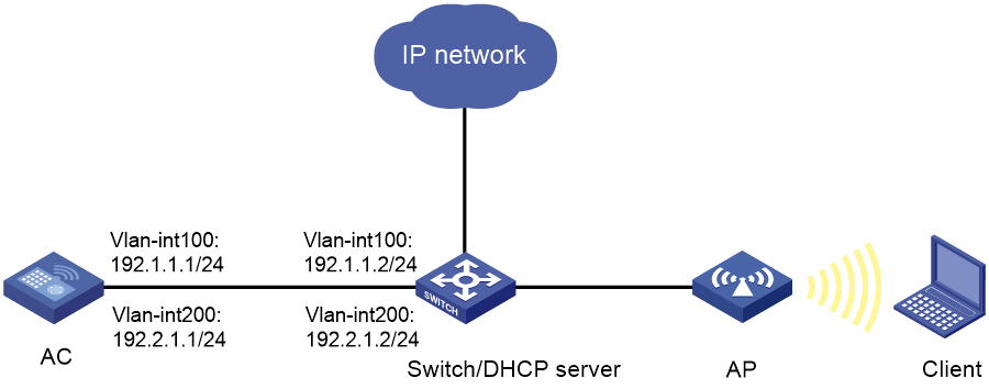
Network configuration
As shown in Figure 1, the switch acts as a DHCP server to assign IP addresses to the AP and client. The AP and AC establish CAPWAP tunnels in VLAN 100. The client accesses the wireless network in VLAN 200.
Configure the AC to use the default IPS policy for attack detection and prevention.
Restrictions and guidelines
Use the actual serial ID of an AP to uniquely identify that AP.
Procedures
Configuring the AC
1. Configure interfaces on the AC:
# Create VLAN 100 and VLAN-interface 100, and assign an IP address to the VLAN interface. The AP will obtain this IP address to establish CAPWAP tunnels with the AC.
<AC> system-view
[AC] vlan 100
[AC-vlan100] quit
[AC] interface vlan-interface 100
[AC-Vlan-interface100] ip address 192.1.1.1 24
[AC-Vlan-interface100] quit
# Create VLAN 200 and VLAN-interface 200, and assign an IP address to the VLAN interface. The client will access the wireless network in this VLAN.
[AC] vlan 200
[AC-vlan200] quit
[AC] interface vlan-interface 200
[AC-Vlan-interface200] ip address 192.2.1.1 24
[AC-Vlan-interface200] quit
# Set the link type of GigabitEthernet 1/0/1 (the port connected to the switch) to trunk. Prevent traffic from VLAN 1 from passing through the port and allow traffic from VLAN 100 and VLAN 200 to pass through the port.
[AC] interface gigabitethernet 1/0/1
[AC-GigabitEthernet1/0/1] port link-type trunk
[AC-GigabitEthernet1/0/1] undo port trunk permit vlan 1
[AC-GigabitEthernet1/0/1] port trunk permit vlan 100 200
[AC-GigabitEthernet1/0/1] quit
2. Configure a wireless service:
# Create service template 1 and enter service template view.
[AC] wlan service-template 1
# Set the SSID to service.
[AC-wlan-st-1] ssid service
# Assign the client to VLAN 200 after it comes online.
[AC-wlan-st-1] vlan 200
# Specify the AKM mode as PSK, and configure the preshared key as 12345678 in plain text.
[AC-wlan-st-1] akm mode psk
[AC-wlan-st-1] preshared-key pass-phrase simple 12345678
# Specify the cipher suite as CCMP and the security IE as RSN.
[AC-wlan-st-1] cipher-suite ccmp
[AC-wlan-st-1] security-ie rsn
# Configure the AC to forward client data traffic. (Skip this step if the client data traffic forwarder is the AC by default.)
[AC-wlan-st-1] client forwarding-location ac
# Enable the service template.
[AC-wlan-st-1] service-template enable
[AC-wlan-st-1] quit
3. Configure the AP:
|
|
NOTE: In large-scale networks, configure AP groups instead of single APs as a best practice. |
# Create an AP named ap1 with model WA6320.
[AC] wlan ap ap1 model WA6320
# Set the serial ID to 219801A28N819CE0002T.
[AC-wlan-ap-ap1] serial-id 219801A28N819CE0002T
[AC-wlan-ap-ap1] quit
# Create AP group group1 and add AP ap1 to AP group group1.
[AC] wlan ap-group group1
[AC-wlan-ap-group-group1] ap ap1
# Bind service template 1 to radio 2 in AP group group1.
[AC-wlan-ap-group-group1] ap-model WA6320
[AC-wlan-ap-group-group1-ap-model-WA6320] radio 2
[AC-wlan-ap-group-group1-ap-model-WA6320-radio-2] service-template 1
# Enable radio 2.
[AC-wlan-ap-group-group1-ap-model-WA6320-radio-2] radio enable
[AC-wlan-ap-group-group1-ap-model-WA6320-radio-2] quit
[AC-wlan-ap-group-group1-ap-model-WA6320] quit
[AC-wlan-ap-group-group1] quit
4. Configure an IP address object group named ipsfilter and specify subnet 192.2.1.0/24 for the object group.
[AC] object-group ip address ipsfilter
[AC-obj-grp-ip-ipsfilter] network subnet 192.2.1.0 24
[AC-obj-grp-ip-ipsfilter] quit
5. Apply the default IPS policy to a DPI application profile and activate the IPS policy settings:
# Create a DPI application profile named sec and enter its view. Apply the default IPS policy to the DPI application profile and set the policy mode to protect.
[AC] app-profile sec
[AC-app-profile-sec] ips apply policy default mode protect
[AC-app-profile-sec] quit
# Activate the IPS policy settings.
[AC] inspect activate
6. Configure a security policy:
# Enter IPv4 security policy view.
[AC] security-policy ip
# Create a rule named ipsfilter to permit the traffic destined for IP addresses in IP address object group ipsfilter and apply DPI application profile sec to the security group.
[AC-security-policy-ip] rule name ipsfilter
[AC-security-policy-ip-10-ipsfilter] destination-ip ipsfilter
[AC-security-policy-ip-10-ipsfilter] action pass
[AC-security-policy-ip-10-ipsfilter] profile sec
[AC-security-policy-ip-10-ipsfilter] quit
# Activate rule matching acceleration.
[AC-security-policy-ip] accelerate enhanced enable
[AC-security-policy-ip] quit
Configuring the switch
1. Configure interfaces on the switch:
# Create VLANs 100 and 200, create VLAN-interface 100 and VLAN-interface 200, and assign IP addresses to VLAN-interface 100 and VLAN-interface 200. The switch will use VLAN 100 to forward the traffic on CAPWAP tunnels between the AC and APs, and use VLAN 200 to forward client traffic.
<Switch> system-view
[Switch] vlan 100
[Switch-vlan100] quit
[Switch] interface vlan-interface 100
[Switch-Vlan-interface100] ip address 192.1.1.2 24
[Switch-Vlan-interface100] quit
[Switch] vlan 200
[Switch-vlan200] quit
[Switch] interface vlan-interface 200
[Switch-Vlan-interface200] ip address 192.2.1.2 24
[Switch-Vlan-interface200] quit
# Configure GigabitEthernet 1/0/1 that connects the switch to the AC as a trunk port.
[Switch] interface gigabitethernet 1/0/1
[Switch-GigabitEthernet1/0/1] port link-type trunk
# Remove the trunk port from VLAN 1, and assign the port to VLAN 100 and VLAN 200.
[Switch-GigabitEthernet1/0/1] undo port trunk permit vlan 1
[Switch-GigabitEthernet1/0/1] port trunk permit vlan 100 200
[Switch-GigabitEthernet1/0/1] quit
# Configure GigabitEthernet 1/0/2 that connects the switch to the AP as a trunk port, and assign the port to VLAN 100.
[Switch] interface gigabitethernet 1/0/2
[Switch-GigabitEthernet1/0/2] port link-type trunk
# Remove the trunk port from VLAN 1, and assign the port to VLAN 100.
[Switch-GigabitEthernet1/0/2] undo port trunk permit vlan 1
[Switch-GigabitEthernet1/0/2] port trunk permit vlan 100
# Specify the PVID of the trunk port as VLAN 100.
[Switch-GigabitEthernet1/0/2] port trunk pvid vlan 100
[Switch-GigabitEthernet1/0/2] quit
# Enable PoE on the trunk port.
[Switch-GigabitEthernet1/0/2] poe enable
[Switch-GigabitEthernet1/0/2] quit
2. Configure DHCP:
# Enable DHCP.
[Switch] dhcp enable
# Create a DHCP address pool named vlan100 to assign IP addresses and other configuration parameters to clients on subnet 192.1.1.0/24.
[Switch] dhcp server ip-pool vlan100
[Switch-dhcp-pool-vlan100] network 192.1.1.0 mask 255.255.255.0
# Exclude IP addresses 192.1.1.1 and 192.1.1.2 from dynamic allocation.
[Switch-dhcp-pool-vlan100] forbidden-ip 192.1.1.1 192.1.1.2
# Specify a gateway.
[Switch-dhcp-pool-vlan100] gateway-list 192.1.1.1
[Switch-dhcp-pool-vlan100] quit
# Create a DHCP address pool named vlan200 to assign IP addresses and other configuration parameters to clients on subnet 192.2.1.0/24.
[Switch] dhcp server ip-pool vlan200
[Switch-dhcp-pool-vlan200] network 192.2.1.0 mask 255.255.255.0
# Exclude IP addresses 192.2.1.1 and 192.2.1.2 from dynamic allocation.
[Switch-dhcp-pool-vlan200] forbidden-ip 192.2.1.1 192.2.1.2
# Specify a gateway and a DNS server.
[Switch-dhcp-pool-vlan200] gateway-list 192.2.1.2
[Switch-dhcp-pool-vlan200] dns-list 192.2.1.2
[Switch-dhcp-pool-vlan200] quit
Verifying the configuration
# Verify that the AC can use the default IPS policy to detect and prevent known network attacks. (Details not shown.)
Configuration files
· AC:
#
vlan 100
#
vlan 200
#
object-group ip address ipsfilter
0 network subnet 192.2.1.0 255.255.255.0
#
wlan service-template 1
ssid service
vlan 200
client forwarding-location ac
akm mode psk
preshared-key pass-phrase cipher $c$3$oLf6pOZ6bxrf25nodjOJKYEfnZ6g6ErccHyQ
cipher-suite ccmp
security-ie rsn
service-template enable
#
interface Vlan-interface100
ip address 192.1.1.1 255.255.255.0
#
interface Vlan-interface200
ip address 192.2.1.1 255.255.255.0
#
interface GigabitEthernet1/0/1
port link-type trunk
undo port trunk permit vlan 1
port trunk permit vlan 100 200
#
app-profile sec
ips apply policy default mode protect
#
wlan ap-group group1
ap ap1
ap-model WA6320
radio 1
radio 2
radio enable
service-template 1
#
wlan ap ap1 model WA6320
serial-id 219801A28N819CE0002T
#
security-policy ip
rule 10 name ipsfilter
action pass
profile sec
destination-ip ipsfilte
· Switch:
#
dhcp enable
#
vlan 100
#
vlan 200
#
dhcp server ip-pool vlan100
gateway-list 192.1.1.1
network 192.1.1.0 mask 255.255.255.0
forbidden-ip 192.1.1.1 192.1.1.2
#
dhcp server ip-pool vlan200
gateway-list 192.2.1.2
network 192.2.1.0 mask 255.255.255.0
dns-list 192.2.1.2
forbidden-ip 192.2.1.1 192.2.1.2
#
interface Vlan-interface100
ip address 192.1.1.2 255.255.255.0
#
interface Vlan-interface200
ip address 192.2.1.2 255.255.255.0
#
interface GigabitEthernet1/0/1
port link-type trunk
undo port trunk permit vlan 1
port trunk permit vlan 100 200
#
interface GigabitEthernet1/0/2
port link-type trunk
undo port trunk permit vlan 1
port trunk permit vlan 100
port trunk pvid vlan 100
poe enable
#
Related documentation
· IPS Command Reference in H3C Access Controllers Command References
· IPS Configuration Guide in H3C Access Controllers Configuration Guides
· Security Policy Command Reference in H3C Access Controllers Command References
· Security Policy Configuration Guide in H3C Access Controllers Configuration Guides
