- Table of Contents
-
- H3C Fixed Port Campus Switches Configuration Examples-6W105
- 00-Applicable hardware and software versions
- 01-Login Management Configuration Examples
- 02-RBAC Configuration Examples
- 03-Software Upgrade Examples
- 04-ISSU Configuration Examples
- 05-Software Patching Examples
- 06-Ethernet Link Aggregation Configuration Examples
- 07-Port Isolation Configuration Examples
- 08-Spanning Tree Configuration Examples
- 09-VLAN Configuration Examples
- 10-VLAN Tagging Configuration Examples
- 11-DHCP Snooping Configuration Examples
- 12-Cross-Subnet Dynamic IP Address Allocation Configuration Examples
- 13-IPv6 over IPv4 Tunneling with OSPFv3 Configuration Examples
- 14-IPv6 over IPv4 GRE Tunnel Configuration Examples
- 15-GRE with OSPF Configuration Examples
- 16-OSPF Configuration Examples
- 17-IS-IS Configuration Examples
- 18-BGP Configuration Examples
- 19-Policy-Based Routing Configuration Examples
- 20-OSPFv3 Configuration Examples
- 21-IPv6 IS-IS Configuration Examples
- 22-Routing Policy Configuration Examples
- 23-IGMP Snooping Configuration Examples
- 24-IGMP Configuration Examples
- 25-MLD Snooping Configuration Examples
- 26-IPv6 Multicast VLAN Configuration Examples
- 27-ACL Configuration Examples
- 28-Traffic Policing Configuration Examples
- 29-GTS and Rate Limiting Configuration Examples
- 30-Traffic Filtering Configuration Examples
- 31-AAA Configuration Examples
- 32-Port Security Configuration Examples
- 33-Portal Configuration Examples
- 34-SSH Configuration Examples
- 35-IP Source Guard Configuration Examples
- 36-Ethernet OAM Configuration Examples
- 37-CFD Configuration Examples
- 38-DLDP Configuration Examples
- 39-VRRP Configuration Examples
- 40-BFD Configuration Examples
- 41-NTP Configuration Examples
- 42-SNMP Configuration Examples
- 43-NQA Configuration Examples
- 44-Mirroring Configuration Examples
- 45-sFlow Configuration Examples
- 46-OpenFlow Configuration Examples
- 47-MAC Address Table Configuration Examples
- 48-Static Multicast MAC Address Entry Configuration Examples
- 49-IP Unnumbered Configuration Examples
- 50-MVRP Configuration Examples
- 51-MCE Configuration Examples
- 52-Attack Protection Configuration Examples
- 53-Smart Link Configuration Examples
- 54-RRPP Configuration Examples
- 55-BGP Route Selection Configuration Examples
- 56-IS-IS Route Summarization Configuration Examples
- 57-VXLAN Configuration Examples
- 58-DRNI Configuration Examples
- 59-IRF 3.1 Configuration Examples
- 60-PTP Configuration Examples
- 61-S-MLAG Configuration Examples
- 62-Puppet Configuration Examples
- 63-802.1X Configuration Examples
- 64-MAC Authentication Configuration Examples
- 65-ISATAP Tunnel and 6to4 Tunnel Configuration Examples
- 66-BIDIR-PIM Configuration Examples
- 67-Congestion Avoidance and Queue Scheduling Configuration Examples
- 68-Basic MPLS Configuration Examples
- 69-MPLS L3VPN Configuration Examples
- 70-MPLS OAM Configuration Examples
- 71-EVPN-DCI over an MPLS L3VPN Network Configuration Examples
- 72-DRNI and EVPN Configuration Examples
- 73-Multicast VPN Configuration Examples
- 74-MPLS TE Configuration Examples
- 75-Control Plane-Based QoS Policy Configuration Examples
- 76-Priority Mapping and Queue Scheduling Configuration Examples
- 77-ARP Attack Protection Configuration Examples
- 78-IRF Software Upgrade Configuration Examples
- 79-IRF Member Replacement Configuration Examples
- 80-Layer 3 Multicast on Multicast Source-Side DR System Configuration Examples
- 81-EVPN Multicast Configuration Examples
- 82-Priority Marking and Queue Scheduling Configuration Examples
- 83-EAA Configuration Examples
- 84-GRE Tunnel Access to MPLS L3VPN Configuration Examples
- 85-MC-NAT Configuration Examples
- 86-M-LAG Configuration Examples (Applicable to M-LAG Versions)
- 87-MOD Configuration Examples
- 88-MPLS L2VPN Configuration Examples
- 89-VPLS Configuration Examples
- 90-SR-MPLS Configuration Examples
- 91-VCF Fabric Configuration Examples
- 92-NetStream Configuration Examples
- 93-Configuration Example for Software Upgrade with Zero Packet Loss by Using GIR in VXLAN M-LAG Network
- 94-Configuration Example for Software Upgrade with Zero Packet Loss by Using GIR in VXLAN DRNI Network
- Related Documents
-
91-VCF Fabric Configuration Examples
Example: Configuring automated deployment for the distributed gateway
Applicable hardware and software versions
Configuring automated deployment
Configuring the Director server
Introduction
The following information provides automated VCF fabric deployment configuration examples.
Prerequisites
The configuration examples were created and verified in a lab environment, and all the devices were started with the factory default configuration. When you are working on a live network, make sure you understand the potential impact of every command on your network.
The following information is provided based on the assumption that you have basic knowledge of automated VCF fabric deployment.
Example: Configuring automated deployment for the distributed gateway
Network configuration
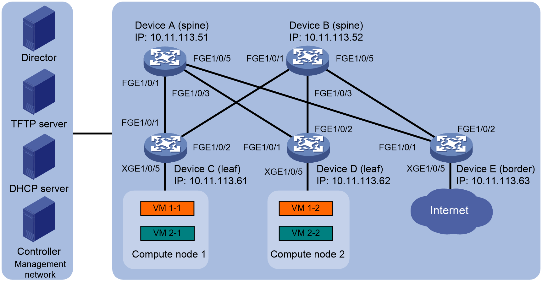
As shown in Figure 1, the distributed VXLAN IP gateway network adopts a spine/leaf architecture. Device A and Device B are spine nodes. Device C and Device D are leaf nodes, which form the distributed VXLAN IP gateway. Device E is a border device and also serves as the border gateway connected to the WAN. Device A to Device E connect to the Director server, DHCP server, and NTP server in the management network through management Ethernet interfaces.
Configure automated VCF fabric deployment to meet the following requirements:
· The DHCP server dynamically allocates IP addresses from the 10.11.113.0/24 network segment to devices.
· After the initial power-on of Device A to Device E, they can automatically complete the automated underlay network deployment based on the template file issued by the Director server.
· Create VM 1-1 and VM 1-2 for tenant a on compute node 1 and compute node 2 respectively. Create VM 2-1 and VM 2-2 for tenant 2. Implement Layer 2 communication within the same VXLAN, and implement communication between different VXLANs and between a VXLAN and WAN through the distributed VXLAN gateway.
Analysis
· Connect the devices and connect the devices and servers to make sure the devices in the network can communicate with one another.
· Configure the DHCP, TFTP, and NTP servers to make sure they can operate correctly.
· This example uses the H3C DR2000 as the Director server for the automated underlay network deployment. The deployment process is visualized, and the devices are automatically incorporated when the deployment is completed. For more information about DR2000 servers, see the user guide of the product. The procedure described in "Configuring the Director server" is for illustration only.
· Perform automated overlay network deployment to ensure configuration consistency on the devices. This document takes the open-source OpenStack Controller system as an example to briefly introduce the deployment process. For more information about the deployment if you choose the solution that uses CloudOS with the VCFC controller, see the H3C VCF fabric solution guide or official documentation based on the installed software version.
Restrictions and guidelines
· The distributed gateway requires configuring the same MAC address for the same VSI interface on each leaf node. This ensures gateway consistency upon VM migrations.
· The spine node for the distributed gateway is only used as the core forwarding point in the underlay network. No overlay network configuration is required.
Applicable hardware and software versions
Table 1 Applicable hardware and software versions
|
Product |
Software version |
|
S6812 switch series S6813 switch series |
Release 6628Pxx |
|
S6550XE-HI switch series |
Release 8106Pxx |
|
S6525XE-HI switch series |
Release 8106Pxx |
|
S5850 switch series |
Not supported |
|
S5570S-EI switch series |
Not supported |
|
S5560X-EI switch series |
Release 6628Pxx |
|
S5560X-HI switch series |
Release 6628Pxx |
|
S5500V2-EI switch series |
Not supported |
|
MS4520V2-30F switch |
Not supported |
|
MS4520V2-30C switch MS4520V2-54C switch |
Not supported |
|
MS4520V2-28S switch MS4520V2-24TP switch |
Not supported |
|
S6520X-HI switch series S6520X-EI switch series |
Release 6628Pxx |
|
S6520X-SI switch series S6520-SI switch series |
Not supported |
|
S5000-EI switch series |
Not supported |
|
MS4600 switch series |
Not supported |
|
ES5500 switch series |
Release 6628Pxx |
|
S5560S-EI switch series S5560S-SI switch series |
Release 63xx (not supported by the S5560S-SI switch series) |
|
S5500V3-24P-SI switch S5500V3-48P-SI switch |
Not supported |
|
S5500V3-SI switch series (excluding the S5500V3-24P-SI and S5500V3-48P-SI switches) |
Not supported |
|
S5170-EI switch series |
Not supported |
|
S5130S-HI switch series S5130S-EI switch series S5130S-SI switch series S5130S-LI series |
Release 63xx (not supported by the S5130S-SI and S5130S-LI switch series) |
|
S5120V2-SI switch series S5120V2-LI switch series |
Not supported |
|
S5120V3-EI switch series |
Not supported |
|
S5120V3-36F-SI switch S5120V3-28P-HPWR-SI switch S5120V3-54P-PWR-SI switch |
Not supported |
|
S5120V3-SI switch series (excluding the S5120V3-36F-SI, S5120V3-28P-HPWR-SI, and S5120V3-54P-PWR-SI switches) |
Not supported |
|
S5120V3-LI switch series |
Not supported |
|
S3600V3-EI switch series |
Not supported |
|
S3600V3-SI switch series |
Not supported |
|
S3100V3-EI switch series S3100V3-SI switch series |
Release 63xx (not supported by the S3100V3-SI switch series) |
|
S5110V2 switch series |
Not supported |
|
S5110V2-SI switch series |
Not supported |
|
S5000V3-EI switch series S5000V5-EI switch series |
Not supported |
|
S5000E-X switch series S5000X-EI switch series |
Not supported |
|
E128C switch E152C switch E500C switch series E500D switch series |
Release 63xx |
|
MS4320V2 switch series MS4320V3 switch series MS4300V2 switch series MS4320 series MS4200 series |
Not supported |
|
WS5850-WiNet switch series |
Not supported |
|
WS5820-WiNet switch series WS5810-WiNet switch series |
Not supported |
|
WAS6000 switch series |
Not supported |
|
IE4300-12P-AC & IE4300-12P-PWR switch IE4300-M switch series IE4320 switch series |
Not supported |
|
IE4520 switch series |
Release 66xx |
|
S5135S-EI switch series |
Not supported |
Configuring automated deployment
Configuring the DHCP server
Configure the following DHCP server settings:
· DHCP address pool: Specify network segment 10.11.113.0/24 for dynamic address allocation.
· TFTP server IP address: 10.11.113.19/24.
· Startup file name: aaa.template.
The file name obtained by the device might vary by device role, such as aaa_leaf.template or aaa_spine.template.
Configuring the Director server
1. Install Director and complete the installation of components such as UBA and network traffic analysis (NTA).
2. Install the DHCP plug to enable AD-DC to set a fixed IP address for the server.
3. Complete basic automated deployment settings, such as network topology type, network scale, and network segments that can be provided by DHCP.
4. Set up network automation parameters, including the MAC address of the master spine node in the network topology, the assignable underlay IP address segment for the master spine node, username, password, user role, and Neutron server parameters.
Deploying the controller node
Deploy the controller node for open-source OpenStack as follows (the procedure is for illustration only):
1. Install the MySQL database.
2. Install RabbitMQ.
3. Install and verify the following services, including adding OpenStack Identity service, creating OpenStack client, and adding image service, nova service, and neutron service.
Deploying compute nodes
Deploy compute nodes for open-source OpenStack as follows (the procedure is for illustration only):
1. Install OpenStack Nova compute components, openvswitch, and neutron ovs agent.
2. Configure management component parameters, including IP address, username, and username and password for communication with RabbitMQ.
3. Restart compute node services.
4. After completing compute node deployment, install Dashboard on the controller node and verify the compute node installation result. You can see the records for the newly added compute nodes, compute node1 and compute node2.
Starting the automated deployment process
Automated underlay network deployment
After the network setup and server configuration are completed, each device (Device A through Device E) starts up without loading configuration to complete the automated underlay network deployment as follows:
1. Obtains an IP address, the IP address of the TFTP server, and a template file name from the DHCP server.
2. Downloads the template file based on the device role from the TFTP server.
3. Parses the template file and compares the current software version with the software version in the template file. If the two versions are inconsistent, the device downloads the new software version.
4. Parses the template file and deploys static configurations.
5. The master spine node Device A uses NETCONF to issue configurations such as loopback IP to Devices B through Device E.
6. Configure IP settings for the interconnect interfaces between spine and leaf nodes, and start the routing protocol to implement Layer 3 VTEP IP connectivity.
|
|
NOTE: After completing the underlay automation, execute the save command on the master spine device to save the configurations such as address allocation. This prevents repeated address allocation for the devices upon restart of the master spine device. |
Deploying tenant overlay network and completing automated device deployment
1. Create a network named Network on the Dashboard.
2. Create two subnets named subnet-1 and subnet-2 on the Dashboard and configure their network addresses.
3. Create a router named router on the Dashboard, and bind the router's interfaces with the two subnets.
4. Create VM 1-1 and VM 1-2 on compute node 1, and create VM 2-1 and VM 2-2 on compute node 2.
Verifying the configuration
1. Verify underlay topology information:
Display VCF fabric topology information on spine node Device A.
[DeviceA] display vcf-fabric topology
Topology Information
----------------------------------------------------------------------------------
* indicates the master spine role among all spines
SpineIP Interface Link LeafIP Status
*10.11.113.51 FortyGigE1/0/1 Up 10.11.113.61 Deploying
FortyGigE1/0/2 Down -- --
FortyGigE1/0/3 Up 10.11.113.62 Deploying
FortyGigE1/0/4 Down -- --
FortyGigE1/0/5 Up 10.11.113.63 Deploying
FortyGigE1/0/6 Down -- --
10.11.113.52 FortyGigE1/0/1 Up 10.11.113.61 Deploying
FortyGigE1/0/2 Down -- --
FortyGigE1/0/3 Up 10.11.113.62 Deploying
FortyGigE1/0/4 Down -- --
FortyGigE1/0/5 Up 10.11.113.63 Deploying
FortyGiE1/0/6 Down -- --
2. Verify automated underlay network deployment:
Display information about automated underlay network deployment on leaf node Device C of the distributed gateway.
[DeviceC] display vcf-fabric underlay autoconfigure
success command:
#
system
clock timezone beijing add 08:00:00
#
system
lldp global enable
lldp compliance cdp
#
system
ospf 1
non-stop-routing
area 0.0.0.0
#
system
interface LoopBack0
#
system
l2vpn enable
#
system
vxlan tunnel mac-learning disable
vxlan tunnel arp-learning disable
#
system
stp global enable
#
system
ntp-service enable
ntp-service unicast-server 10.11.113.136 vpn-instance mgmt
#
system
netconf soap https enable
netconf ssh server enable
restful https enable
#
system
info-center loghost vpn-instance mgmt 10.11.113.136
#
system
local-user admin
password ******
service-type https
authorization-attribute user-role network-admin
#
system
line vty 0 63
authentication-mode scheme
user-role network-admin
#
system
vcf-fabric topology enable
#
system
neutron
rabbit user openstack
rabbit password ******
rabbit host ip 10.11.113.136 vpn-instance mgmt
restful user admin password ******
vpn-target 1:1 export-extcommunity
vsi-mac 789c-2f5f-0200
network-type distributed-vxlan
l2agent enable
l3agent enable
#
system
snmp-agent
snmp-agent community read public
snmp-agent community write private
snmp-agent sys-info version all
snmp-agent packet max-size 4096
snmp-agent target-host trap address udp-domain 192.181.1.30 vpn-insta
nce mgmt params securityname public v2c
#
system
telnet server enable
local-user admin
password ******
service-type telnet http https
authorization-attribute user-role network-admin
#
system
netconf soap http enable
netconf soap https enable
local-user admin
password ******
service-type http https
authorization-attribute user-role network-admin
#
system
bgp 100
non-stop-routing
address-family l2vpn evpn
#
Uplink interface:
FortyGigE1/0/1
FortyGigE1/0/2
IRF allocation:
Self Bridge Mac: 00e0-fc00-5100
IRF Status: No
Member List: [1]
BGP peer configuration:
10.100.16.17
10.100.16.16
3. Verify automated overlay network deployment:
Display VSI and VPN instance configurations on leaf node Device C of the distributed gateway.
[DeviceC] display current-configuration configuration vsi
#
vsi vxlan10071
gateway vsi-interface 8190
vxlan 10071
evpn encapsulation vxlan
route-distinguisher auto
vpn-target auto export-extcommunity
vpn-target auto import-extcommunity
#
return
[DeviceC] display current-configuration interface Vsi-interface
interface Vsi-interface4091
ip binding vpn-instance neutron-1015
ip address 108.1.0.1 255.255.0.0 sub
mac-address 789c-2f5f-0200
arp mode uni
distributed-gateway local
#
[DeviceC] display ip vpn-instance
Total VPN-Instances configured : 6
VPN-Instance Name RD Create time
mgmt 2018/04/17 08:49:59
neutron-1016 4227879168:1016 2018/04/17 08:50:59
neutron-1015 4227879168:1015 2018/04/17 08:51:01
neutron-1018 4227879168:1018 2018/04/17 08:51:03
neutron-1017 4227879168:1017 2018/04/17 08:51:07
neutron-1021 4227879168:1021 2018/04/17 08:51:08
4. Verify connectivity between VMs:
Access the console of VM 1-1 on compute node 1 and execute a ping operation. VM 2-2 on compute node 2 can be pinged successfully.
$ ping 10.1.1.3
Ping 10.1.1.3 (10.1.1.3): 56 data bytes, press CTRL_C to break
56 bytes from 10.1.1.3: icmp_seq=0 ttl=254 time=10.000 ms
56 bytes from 10.1.1.3: icmp_seq=1 ttl=254 time=4.000 ms
56 bytes from 10.1.1.3: icmp_seq=2 ttl=254 time=4.000 ms
56 bytes from 10.1.1.3: icmp_seq=3 ttl=254 time=3.000 ms
56 bytes from 10.1.1.3: icmp_seq=4 ttl=254 time=3.000 ms
--- Ping statistics for 10.1.1.3 ---
5 packet(s) transmitted, 5 packet(s) received, 0.0% packet loss
round-trip min/avg/max/std-dev = 3.000/4.800/10.000/2.638 ms
Configuration files
· Main underlay configuration on leaf node Device C:
#
irf mac-address persistent always
irf auto-update enable
undo irf link-delay
irf member 1 priority 1
#
vxlan tunnel mac-learning disable
#
ospf 1
non-stop-routing
area 0.0.0.0
#
lldp compliance cdp
lldp global enable
#
interface LoopBack0
ip address 19.1.1.254 255.255.255.255
#
interface FortyGigE1/0/1
port link-mode route
ip address unnumbered interface LoopBack0
ospf network-type p2p
ospf 1 area 0.0.0.0
lldp compliance admin-status cdp txrx
lldp management-address arp-learning
lldp tlv-enable basic-tlv management-address-tlv interface LoopBack0
#
interface FortyGigE1/0/2
port link-mode route
ip address unnumbered interface LoopBack0
ospf network-type p2p
ospf 1 area 0.0.0.0
lldp compliance admin-status cdp txrx
lldp management-address arp-learning
lldp tlv-enable basic-tlv management-address-tlv interface LoopBack0
#
bgp 100
non-stop-routing
peer 200.1.15.152 as-number 100
peer 200.1.15.152 connect-interface LoopBack0
peer 200.1.15.152 password cipher $c$3$CRkr6IFvbGrUgoWHuUCYfSf3XLYWbQ==
peer 200.1.15.153 as-number 100
peer 200.1.15.153 connect-interface LoopBack0
peer 200.1.15.153 password cipher $c$3$NzsdiaPMbqkfL5DJsga/5QHtP+w5tg==
#
address-family l2vpn evpn
peer 200.1.15.152 enable
peer 200.1.15.153 enable
· Main overlay configuration on leaf node Device C:
#
ip vpn-instance neutron-1017
route-distinguisher 4227879168:1017
description d3ca707e-ce59-4682-b2d8-7151744993a2
vpn-target 1017:1017 import-extcommunity
vpn-target 1017:1017 1:1 export-extcommunity
#
ip vpn-instance neutron-1018
route-distinguisher 4227879168:1018
description a9c509ca-8ec3-4860-bb03-4a6c9eae2698
vpn-target 1018:1018 import-extcommunity
vpn-target 1018:1018 1:1 export-extcommunity
#
interface vsi-interface4088
ip binding vpn-instance neutron-1018
ip address 10.1.1.1 255.255.255.0 //Gateway address for VMs in VXLAN 10081
mac-address 789c-2f5f-0200
arp mode uni
distributed-gateway local
#
interface vsi-interface4089
ip binding vpn-instance neutron-1018
ip address 10.1.11.1 255.255.255.0 //Gateway address for VMs in VXLAN 10018
mac-address 789c-2f5f-0200
arp mode uni
distributed-gateway local
#
l2vpn enable
#
vsi vxlan10081
gateway vsi-interface 4088
arp suppression enable
flooding disable all
vxlan 10081
evpn encapsulation vxlan //Create an EVPN instance, and enable auto generation of RDs and RTs for the EVPN instance
route-distinguisher auto
vpn-target auto export-extcommunity
vpn-target auto import-extcommunity
#
vsi vxlan10018
gateway vsi-interface 4089
arp suppression enable
flooding disable all
vxlan 10018
evpn encapsulation vxlan //Create an EVPN instance, and enable auto generation of RDs and RTs for the EVPN instance
route-distinguisher auto
vpn-target auto export-extcommunity
vpn-target auto import-extcommunity
#
· Main AC interface configuration on leaf node Device C:
#
interface Ten-GigabieEthernet1/0/5
port link-mode bridge
lldp compliance admin-status cdp txrx
service-instance 100
encapsulation s-vid 4088
xconnect vsi vxlan10018
service-instance 101
encapsulation s-vid 4089
xconnect vsi vxlan10081
#