- Table of Contents
-
- H3C Fixed Port Campus Switches Configuration Examples-6W105
- 00-Applicable hardware and software versions
- 01-Login Management Configuration Examples
- 02-RBAC Configuration Examples
- 03-Software Upgrade Examples
- 04-ISSU Configuration Examples
- 05-Software Patching Examples
- 06-Ethernet Link Aggregation Configuration Examples
- 07-Port Isolation Configuration Examples
- 08-Spanning Tree Configuration Examples
- 09-VLAN Configuration Examples
- 10-VLAN Tagging Configuration Examples
- 11-DHCP Snooping Configuration Examples
- 12-Cross-Subnet Dynamic IP Address Allocation Configuration Examples
- 13-IPv6 over IPv4 Tunneling with OSPFv3 Configuration Examples
- 14-IPv6 over IPv4 GRE Tunnel Configuration Examples
- 15-GRE with OSPF Configuration Examples
- 16-OSPF Configuration Examples
- 17-IS-IS Configuration Examples
- 18-BGP Configuration Examples
- 19-Policy-Based Routing Configuration Examples
- 20-OSPFv3 Configuration Examples
- 21-IPv6 IS-IS Configuration Examples
- 22-Routing Policy Configuration Examples
- 23-IGMP Snooping Configuration Examples
- 24-IGMP Configuration Examples
- 25-MLD Snooping Configuration Examples
- 26-IPv6 Multicast VLAN Configuration Examples
- 27-ACL Configuration Examples
- 28-Traffic Policing Configuration Examples
- 29-GTS and Rate Limiting Configuration Examples
- 30-Traffic Filtering Configuration Examples
- 31-AAA Configuration Examples
- 32-Port Security Configuration Examples
- 33-Portal Configuration Examples
- 34-SSH Configuration Examples
- 35-IP Source Guard Configuration Examples
- 36-Ethernet OAM Configuration Examples
- 37-CFD Configuration Examples
- 38-DLDP Configuration Examples
- 39-VRRP Configuration Examples
- 40-BFD Configuration Examples
- 41-NTP Configuration Examples
- 42-SNMP Configuration Examples
- 43-NQA Configuration Examples
- 44-Mirroring Configuration Examples
- 45-sFlow Configuration Examples
- 46-OpenFlow Configuration Examples
- 47-MAC Address Table Configuration Examples
- 48-Static Multicast MAC Address Entry Configuration Examples
- 49-IP Unnumbered Configuration Examples
- 50-MVRP Configuration Examples
- 51-MCE Configuration Examples
- 52-Attack Protection Configuration Examples
- 53-Smart Link Configuration Examples
- 54-RRPP Configuration Examples
- 55-BGP Route Selection Configuration Examples
- 56-IS-IS Route Summarization Configuration Examples
- 57-VXLAN Configuration Examples
- 58-DRNI Configuration Examples
- 59-IRF 3.1 Configuration Examples
- 60-PTP Configuration Examples
- 61-S-MLAG Configuration Examples
- 62-Puppet Configuration Examples
- 63-802.1X Configuration Examples
- 64-MAC Authentication Configuration Examples
- 65-ISATAP Tunnel and 6to4 Tunnel Configuration Examples
- 66-BIDIR-PIM Configuration Examples
- 67-Congestion Avoidance and Queue Scheduling Configuration Examples
- 68-Basic MPLS Configuration Examples
- 69-MPLS L3VPN Configuration Examples
- 70-MPLS OAM Configuration Examples
- 71-EVPN-DCI over an MPLS L3VPN Network Configuration Examples
- 72-DRNI and EVPN Configuration Examples
- 73-Multicast VPN Configuration Examples
- 74-MPLS TE Configuration Examples
- 75-Control Plane-Based QoS Policy Configuration Examples
- 76-Priority Mapping and Queue Scheduling Configuration Examples
- 77-ARP Attack Protection Configuration Examples
- 78-IRF Software Upgrade Configuration Examples
- 79-IRF Member Replacement Configuration Examples
- 80-Layer 3 Multicast on Multicast Source-Side DR System Configuration Examples
- 81-EVPN Multicast Configuration Examples
- 82-Priority Marking and Queue Scheduling Configuration Examples
- 83-EAA Configuration Examples
- 84-GRE Tunnel Access to MPLS L3VPN Configuration Examples
- 85-MC-NAT Configuration Examples
- 86-M-LAG Configuration Examples (Applicable to M-LAG Versions)
- 87-MOD Configuration Examples
- 88-MPLS L2VPN Configuration Examples
- 89-VPLS Configuration Examples
- 90-SR-MPLS Configuration Examples
- 91-VCF Fabric Configuration Examples
- 92-NetStream Configuration Examples
- 93-Configuration Example for Software Upgrade with Zero Packet Loss by Using GIR in VXLAN M-LAG Network
- 94-Configuration Example for Software Upgrade with Zero Packet Loss by Using GIR in VXLAN DRNI Network
- Related Documents
-
84-GRE Tunnel Access to MPLS L3VPN Configuration Examples
Example: Configuring GRE tunnel access to an MPLS L3VPN
Applicable hardware and software versions
Configuring an IGP on the MPLS backbone
Configuring basic MPLS and MPLS LDP on the MPLS backbone to establish LDP LSPs
Configuring VPN instances on PE 1 and CE 1 and establishing a GRE tunnel to connect CE 1 to PE 1
Configuring a VPN instance on PE 2 to allow CE 2 access to PE 2
Establishing EBGP peers between PEs and CEs to redistributing VPN routes
Establishing MP-IBGP peers between PEs
Introduction
In an MPLS L3VPN, a CE is typically connected to a PE directly. In some networks, a direct connection might not be available between a CE and a PE. In such scenarios, you can configure a GRE tunnel between the CE and PE to establish a virtual point-to-point link. This setup allows the CE and PE to communicate as if they were directly connected.
Prerequisites
The configuration examples were created and verified in a lab environment, and all the devices were started with the factory default configuration. When you are working on a live network, make sure you understand the potential impact of every command on your network.
The following information is provided based on the assumption that you have basic knowledge MPLS L3VPN and GRE.
Example: Configuring GRE tunnel access to an MPLS L3VPN
Network configuration
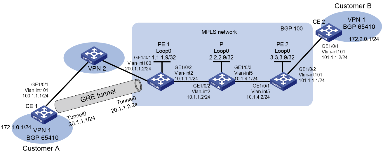
As shown in Figure 1, Customer A and Customer B belong to VPN 1. Deploy an MPLS L3VPN to securely transmit user data between Customer A and Customer B through the VPN.
· PE 1 and PE 2 are edge devices of the MPLS backbone network.
· CE 1 and CE 2 are customer edge devices for VPN 1.
· A network (VPN 2) exists between CE 1 and PE 1. CE 1 and CE 2 are able to route to each other.
Analysis
· To transfer packets on the MPLS network, configure an IGP routing protocol on the MPLS backbone, and use LDP to distribute public network (outer) labels to VPN packets.
· To transport VPN routes and allocate VPN (inner) labels, establish an MP-IBGP peer relationship between the PEs.
· To establish a logical direct connection between CE 1 and PE 1, configure a GRE tunnel between them.
Applicable hardware and software versions
The following matrix shows the hardware and software versions to which this configuration example is applicable:
|
Hardware |
Software version |
|
S6812 switch series S6813 switch series |
Release 6615Pxx, Release 6628Pxx |
|
S6550XE-HI switch series |
Release 6008 and later, Release 8106Pxx |
|
S6525XE-HI switch series |
Release 6008 and later, Release 8106Pxx |
|
S5850 switch series |
Not supported |
|
S5570S-EI switch series |
Not supported |
|
S5560X-EI switch series |
Release 65xx, Release 6615Pxx, Release 6628Pxx |
|
S5560X-HI switch series |
Release 65xx, Release 6615Pxx, Release 6628Pxx |
|
S5500V2-EI switch series |
Release 65xx, Release 6615Pxx, Release 6628Pxx |
|
MS4520V2-30F switch |
Release 65xx, Release 6615Pxx, Release 6628Pxx |
|
MS4520V2-30C switch MS4520V2-54C switch |
Release 65xx, Release 6615Pxx, Release 6628Pxx |
|
MS4520V2-28S 1 switch MS4520V2-24TP switch |
Not supported |
|
S6520X-HI switch series S6520X-EI switch series |
Release 65xx, Release 6615Pxx, Release 6628Pxx |
|
S6520X-SI switch series S6520-SI switch series |
Release 65xx, Release 6615Pxx, Release 6628Pxx |
|
S5000-EI switch series |
Release 65xx, Release 6615Pxx, Release 6628Pxx |
|
MS4600 switch series |
Release 65xx, Release 6615Pxx, Release 6628Pxx |
|
ES5500 switch series |
Release 65xx, Release 6615Pxx, Release 6628Pxx |
|
S5560S-EI switch series S5560S-SI switch series |
Not supported |
|
S5500V3-24P-SI switch S5500V3-48P-SI switch |
Not supported |
|
S5500V3-SI switch series (except S5500V3-24P-SI and S5500V3-48P-SI) |
Not supported |
|
S5170-EI switch series |
Not supported |
|
S5130S-HI switch series S5130S-EI switch series S5130S-SI switch series S5130S-LI switch series |
Not supported |
|
S5120V2-SI switch series S5120V2-LI switch series |
Not supported |
|
S5120V3-EI switch series |
Not supported |
|
S5120V3-36F-SI switch S5120V3-28P-HPWR-SI switch S5120V3-54P-PWR-SI |
Not supported |
|
S5120V3-SI switch series (except S5120V3-36F-SI, S5120V3-28P-HPWR-SI, and S5120V3-54P-PWR-SI) |
Not supported |
|
S5120V3-LI switch series |
Not supported |
|
S3600V3-EI switch series |
Not supported |
|
S3600V3-SI switch series |
Not supported |
|
S3100V3-EI switch series S3100V3-SI switch series |
Not supported |
|
S5110V2 switch series |
Not supported |
|
S5110V2-SI switch series |
Not supported |
|
S5000V3-EI switch series S5000V5-EI switch series |
Not supported |
|
S5000E-X switch series S5000X-EI switch series |
Not supported |
|
E128C 1 switch E152C switch E500C switch series E500D switch series |
Not supported |
|
MS4320V2 switch series MS4320V3 switch series MS4300V2 switch series MS4320 switch series MS4200 switch series |
Not supported |
|
WS5850-WiNet switch series |
Not supported |
|
WS5820-WiNet switch series WS5810-WiNet switch series |
Not supported |
|
WAS6000 switch series |
Not supported |
|
IE4300-12P-AC switch IE4300-12P-PWR switch IE4300-M switch series IE4320 switch series |
Not supported |
|
IE4520 switch series |
Not supported |
|
S5135S-EI switch |
Not supported |
Restrictions and guidelines
When an interface is bound to a VPN instance, the settings (including IP address) on the interface will be cleared. Therefore, bind an interface to a VPN instance before you configure other settings on the interface.
For the S5570S-EI, S5500V3-SI, S3600V3-EI, and S3600V3-SI switch series, before switching a Layer 2 Ethernet interface to a Layer 3 Ethernet interface or creating a Layer 3 aggregate interface, use the reserve-vlan-interface command to reserve local VLAN interface resources. For more information about the reserve-vlan-interface command, see the VLAN configuration and VLAN commands for your product.
Procedures
Configuring an IGP on the MPLS backbone
This example uses OSPF to implement IP connectivity between the PE and P devices on the MPLS backbone.
1. Configure PE 1:
# Configure IP addresses for the loopback interface and the backbone network interfaces.
<PE1> system-view
[PE1] interface loopback 0
[PE1-LoopBack0] ip address 1.1.1.9 32
[PE1-LoopBack0] quit
[PE1] vlan 2
[PE1-vlan2] port GigabitEthernet 1/0/2
[PE1-vlan2] quit
[PE1] interface vlan-interface 2
[PE1-Vlan-interface2] ip address 10.1.1.1 24
[PE1-Vlan-interface2] quit
# Enable OSPF on the interfaces attached to the backbone network.
[PE1] ospf
[PE1-ospf-1] area 0
[PE1-ospf-1-area-0.0.0.0] network 10.1.1.0 0.0.0.255
[PE1-ospf-1-area-0.0.0.0] network 1.1.1.9 0.0.0.0
[PE1-ospf-1-area-0.0.0.0] quit
[PE1-ospf-1] quit
2. Configure P:
# Configure IP addresses for the loopback interface and the backbone network interfaces.
<P> system-view
[P] interface loopback 0
[P-LoopBack0] ip address 2.2.2.9 32
[P-LoopBack0] quit
[P] vlan 2
[P-vlan2] port GigabitEthernet 1/0/2
[P-vlan2] quit
[P] vlan 5
[P-vlan5] port GigabitEthernet 1/0/3
[P-vlan5] quit
[P] interface vlan-interface 2
[P-Vlan-interface2] ip address 10.1.1.2 24
[P-Vlan-interface2] quit
[P] interface vlan-interface 5
[P-Vlan-interface5] ip address 10.1.4.1 24
[P-Vlan-interface5] quit
# Enable OSPF on the interfaces attached to the backbone network.
[P] ospf
[P-ospf-1] area 0
[P-ospf-1-area-0.0.0.0] network 10.1.1.0 0.0.0.255
[P-ospf-1-area-0.0.0.0] network 10.1.4.0 0.0.0.255
[P-ospf-1-area-0.0.0.0] network 2.2.2.9 0.0.0.0
[P-ospf-1-area-0.0.0.0] quit
[P-ospf-1] quit
3. Configure PE 2:
# Configure IP addresses for the loopback interface and the backbone network interfaces.
<PE2> system-view
[PE2] interface loopback 0
[PE2-LoopBack0] ip address 3.3.3.9 32
[PE2-LoopBack0] quit
[PE2] vlan 5
[PE2-vlan5] port GigabitEthernet 1/0/1
[PE2-vlan5] quit
[PE2] interface vlan-interface 5
[PE2-Vlan-interface5] ip address 10.1.4.2 24
[PE2-Vlan-interface5] quit
# Enable OSPF on the interfaces attached to the backbone network.
[PE2] ospf
[PE2-ospf-1] area 0
[PE2-ospf-1-area-0.0.0.0] network 10.1.4.0 0.0.0.255
[PE2-ospf-1-area-0.0.0.0] network 3.3.3.9 0.0.0.0
[PE2-ospf-1-area-0.0.0.0] quit
[PE2-ospf-1] quit
After the configuration is completed, PE 1, P, and PE 2 can establish OSPF neighbor relationships. Execute the display ospf peer command to verify that the neighbors are in full state. Execute the display ip routing-table command to verify that the PEs have learned the routes to the loopback interfaces of each other.
Use PE 1 as an example:
[PE1] display ospf peer verbose
OSPF Process 1 with Router ID 1.1.1.9
Neighbors
Area 0.0.0.0 interface 10.1.1.1(Vlan-interface2)'s neighbors
Router ID: 2.2.2.9 Address: 10.1.1.2 GR State: Normal
State: Full Mode: Nbr is Master Priority: 1
DR: 10.1.1.2 BDR: 10.1.1.1 MTU: 0
Options is 0x02 (-|-|-|-|-|-|E|-)
Dead timer due in 38 sec
Neighbor is up for 17:30:25
Authentication Sequence: [ 0 ]
Neighbor state change count: 6
BFD status: Disabled
[PE1] display ip routing-table protocol ospf
Summary Count : 5
OSPF Routing table Status : <Active>
Summary Count : 3
Destination/Mask Proto Pre Cost NextHop Interface
2.2.2.9/32 OSPF 10 1 10.1.1.2 Vlan2
3.3.3.9/32 OSPF 10 2 10.1.1.2 Vlan2
10.1.4.0/24 OSPF 10 2 10.1.1.2 Vlan2
OSPF Routing table Status : <Inactive>
Summary Count : 2
Destination/Mask Proto Pre Cost NextHop Interface
1.1.1.9/32 OSPF 10 0 1.1.1.9 Loop0
10.1.1.0/24 OSPF 10 1 10.1.1.1 Vlan2
Configuring basic MPLS and MPLS LDP on the MPLS backbone to establish LDP LSPs
1. Configure PE 1:
[PE1] mpls lsr-id 1.1.1.9
[PE1] mpls ldp
[PE1-ldp] quit
[PE1] interface vlan-interface 2
[PE1-Vlan-interface2] mpls enable
[PE1-Vlan-interface2] mpls ldp enable
[PE1-Vlan-interface2] quit
2. Configure P:
[P] mpls lsr-id 2.2.2.9
[P] mpls ldp
[P-ldp] quit
[P] interface vlan-interface 2
[P-Vlan-interface2] mpls enable
[P-Vlan-interface2] mpls ldp enable
[P-Vlan-interface2] quit
[P] interface vlan-interface 5
[P-Vlan-interface5] mpls enable
[P-Vlan-interface5] mpls ldp enable
[P-Vlan-interface5] quit
3. Configure PE 2:
[PE2] mpls lsr-id 3.3.3.9
[PE2] mpls ldp
[PE2-ldp] quit
[PE2] interface vlan-interface 5
[PE2-Vlan-interface5] mpls enable
[PE2-Vlan-interface5] mpls ldp enable
[PE2-Vlan-interface5] quit
Execute the display mpls ldp peer command to verify that LDP sessions in Operational state have been established between PE 1, P, and PE 2. Execute the display mpls ldp lsp command to verify that the LSPs have been established by LDP.
Use PE1 as an example.
[PE1] display mpls ldp peer
Total number of peers: 1
Peer LDP ID State Role GR MD5 KA Sent/Rcvd
2.2.2.9:0 Operational Passive Off Off 5/5
[PE1] display mpls ldp lsp
Status Flags: * - stale, L - liberal, B - backup
FECs: 4 Ingress: 1 Transit: 1 Egress: 3
FEC In/Out Label Nexthop OutInterface
1.1.1.9/32 3/-
-/1151(L)
2.2.2.9/32 -/3 10.1.1.2 Vlan2
1151/3 10.1.1.2 Vlan2
3.3.3.9/32 -/1150 10.1.1.2 Vlan2
1150/1150 10.1.1.2 Vlan2
Configuring VPN instances on PE 1 and CE 1 and establishing a GRE tunnel to connect CE 1 to PE 1
Configuring VPN instances on PE 1 and CE 1
1. Configure PE 1:
# Create a VPN instance named vpn1 on PE 1.
[PE1] ip vpn-instance vpn1
# Configure the RD of the VPN instance as 100:1.
[PE1-vpn-instance-vpn1] route-distinguisher 100:1
# Configure route targets for the VPN instance.
[PE1-vpn-instance-vpn1] vpn-target 100:1 import-extcommunity
[PE1-vpn-instance-vpn1] vpn-target 100:1 export-extcommunity
[PE1-vpn-instance-vpn1] quit
# Bind VLAN-interface 100 to the VPN instance.
[PE1] vlan 100
[PE1-vlan100] port GigabitEthernet 1/0/1
[PE1-vlan100] quit
[PE1] interface vlan-interface 100
[PE1-Vlan-interface100] ip binding vpn-instance vpn1
[PE1-Vlan-interface100] ip address 200.1.1.2 24
[PE1-Vlan-interface100] quit
2. Configure CE 1:
# Create a VPN instance named vpn1 on CE 1.
[CE1] ip vpn-instance vpn1
# Configure the RD of the VPN instance as 100:1.
[CE1-vpn-instance-vpn1] route-distinguisher 100:1
# Configure route targets for the VPN instance.
[CE1-vpn-instance-vpn1] vpn-target 100:1 import-extcommunity
[CE1-vpn-instance-vpn1] vpn-target 100:1 export-extcommunity
[CE1-vpn-instance-vpn1] quit
# Bind VLAN-interface 101 to the VPN instance.
[CE1] vlan 101
[CE1-vlan101] port GigabitEthernet 1/0/1
[CE1-vlan101] quit
[CE1] interface vlan-interface 101
[CE1-Vlan-interface101] ip binding vpn-instance vpn1
[CE1-Vlan-interface101] ip address 100.1.1.1 24
[CE1-Vlan-interface101] quit
Configuring a GRE tunnel between CE 1 and PE 1
1. Configure CE 1:
# Create service loopback group 1 and configure the service type as tunnel. Assign interface GigabitEthernet 1/0/3 to service loopback group 1. (For the S6550XE-HI, S6525XE-HI, and S5850 switch series, you must create a tunnel-type service loopback group to enable the reception and transmission of tunnel packets.)
[CE1] service-loopback group 1 type tunnel
# Assign interface GigabitEthernet 1/0/3 to service loopback group 1.
[CE1] interface GigabitEthernet 1/0/3
[CE1-GigabitEthernet1/0/3] port service-loopback group 1
[CE1-GigabitEthernet1/0/3] quit
# Create tunnel interface Tunnel 0, and specify the tunnel mode as GRE/IPv4.
[CE1] interface tunnel 0 mode gre
# Specify a VPN instance for the tunnel source address.
[CE1-Tunnel0] ip binding vpn-instance vpn1
# Assign an IP address to interface Tunnel 0.
[CE1-Tunnel0] ip address 20.1.1.1 255.255.255.0
# Configure the tunnel source address as the IP address of VLAN-interface 101 on CE 1.
[CE1-Tunnel0] source vlan-interface 101
# Configure the tunnel destination address as the IP address of VLAN-interface 100 on PE 1.
[CE1-Tunnel0] destination 200.1.1.2
# Specify a VPN instance for the tunnel destination address.
[CE1-Tunnel0] tunnel vpn-instance vpn1
[CE1-Tunnel0] quit
# Configure a static route for Customer A to reach Customer B via Tunnel 0.
[CE1] ip route-static vpn-instance vpn1 172.2.0.0 24 tunnel 0
2. Configure PE 1:
# Create service loopback group 1 and configure the service type as tunnel. Assign interface GigabitEthernet 1/0/3 to service loopback group 1. (For the S6550XE-HI, S6525XE-HI, and S5850 switch series, you must create a tunnel-type service loopback group to enable the reception and transmission of tunnel packets.)
[PE1] service-loopback group 1 type tunnel
# Assign interface GigabitEthernet 1/0/3 to service loopback group 1.
[PE1] interface GigabitEthernet 1/0/3
[PE1-GigabitEthernet1/0/3] port service-loopback group 1
[PE1-GigabitEthernet1/0/3] quit
# Create tunnel interface Tunnel 0, and specify the tunnel mode as GRE/IPv4.
[PE1] interface tunnel 0 mode gre
# Specify a VPN instance for the tunnel source address.
[PE1-Tunnel0] ip binding vpn-instance vpn1
# Assign an IP address to interface Tunnel 0.
[PE1-Tunnel0] ip address 20.1.1.2 255.255.255.0
# Configure the tunnel source address as the IP address of VLAN-interface 100 on PE 1.
[PE1-Tunnel0] source vlan-interface 100
# Configure the tunnel destination address as the IP address of VLAN-interface 101 on CE 1.
[PE1-Tunnel0] destination 100.1.1.1
# Specify a VPN instance for the tunnel destination address.
[PE1-Tunnel0] tunnel vpn-instance vpn1
[PE1-Tunnel0] quit
# Configure a static route for Customer B to reach Customer A via Tunnel 0.
[PE1] ip route-static vpn-instance vpn1 172.1.0.0 24 Tunnel 0
Configuring a VPN instance on PE 2 to allow CE 2 access to PE 2
1. Configure PE 2:
# Create a VPN instance named vpn1 on PE 2.
[PE2] ip vpn-instance vpn1
# Configure an RD of the VPN instance.
[PE2-vpn-instance-vpn1] route-distinguisher 100:1
# Configure the import target and export target for the VPN instance, which must be the same as the export target and import target on PE 1.
[PE2-vpn-instance-vpn1] vpn-target 100:1 import-extcommunity
[PE2-vpn-instance-vpn1] vpn-target 100:1 export-extcommunity
[PE2-vpn-instance-vpn1] quit
# Bind VLAN-interface 101 to the VPN instance.
[PE2] vlan 101
[PE2-vlan101] port GigabitEthernet 1/0/2
[PE2-vlan101] quit
[PE2] interface vlan-interface 101
[PE2-Vlan-interface101] ip binding vpn-instance vpn1
[PE2-Vlan-interface101] ip address 101.1.1.1 24
[PE2-Vlan-interface101] quit
2. Configure CE 2:
Configure IP addresses for interfaces on CE 2 as shown in Figure 1. (Details not shown.)
After the configuration is completed, execute the display ip vpn-instance command on PE 2 to view the VPN instance configuration. PE 2 can ping the connected CE 2.
[PE2] display ip vpn-instance
Total VPN-Instances configured : 1
VPN-Instance Name RD Create time
vpn1 100:1 2016/06/22 13:20:08
[PE2] ping -vpn-instance vpn1 101.1.1.2
Ping 10.1.4.2 (101.1.1.2): 56 data bytes, press CTRL_C to break
56 bytes from 101.1.1.2: icmp_seq=0 ttl=255 time=1.000 ms
56 bytes from 101.1.1.2: icmp_seq=1 ttl=255 time=2.000 ms
56 bytes from 101.1.1.2: icmp_seq=2 ttl=255 time=0.000 ms
56 bytes from 101.1.1.2: icmp_seq=3 ttl=255 time=1.000 ms
56 bytes from 101.1.1.2: icmp_seq=4 ttl=255 time=0.000 ms
--- Ping statistics for 10.1.1.1 ---
5 packet(s) transmitted, 5 packet(s) received, 0.0% packet loss
round-trip min/avg/max/std-dev = 0.000/0.800/2.000/0.748 ms
Establishing EBGP peers between PEs and CEs to redistributing VPN routes
1. Configure PE 1:
# Create BGP process 100 on PE 1.
[PE1] bgp 100
# Specify CE 1 as the peer. Redistribute the direct routes in the routing table of PE 1 into the routing table of the BGP-VPN instance.
[PE1-bgp-default] ip vpn-instance vpn1
[PE1-bgp-default-vpn1] peer 20.1.1.1 as-number 65410
[PE1-bgp-default-vpn1] address-family ipv4 unicast
[PE1-bgp-default-ipv4-vpn1] peer 20.1.1.1 enable
[PE1-bgp-default-ipv4-vpn1] import-route direct
[PE1-bgp-default-ipv4-vpn1] quit
[PE1-bgp-default-vpn1] quit
2. Configure PE 2:
# Create BGP process 100 on PE 2.
[PE2] bgp 100
# Specify CE 2 as the peer. Redistribute the direct routes in the routing table of PE 2 into the routing table of the BGP-VPN instance.
[PE2-bgp-default] ip vpn-instance vpn1
[PE2-bgp-default-vpn1] peer 101.1.1.2 as-number 65410
[PE2-bgp-default-vpn1] address-family ipv4 unicast
[PE2-bgp-default-ipv4-vpn1] peer 101.1.1.2 enable
[PE2-bgp-default-ipv4-vpn1] import-route direct
[PE2-bgp-default-ipv4-vpn1] quit
[PE2-bgp-default-vpn1] quit
3. Configure CE 1:
# Create BGP process 65410 on CE 1. Specify PE 1 as the peer with AS number 100.
<CE1> system-view
[CE1] bgp 65410
[CE1-bgp-default] peer 20.1.1.2 as-number 100
# Enable CE 1 to exchange IPv4 unicast routing information with peer 20.1.1.2.
[CE1-bgp-default] address-family ipv4 unicast
[CE1-bgp-default-ipv4] peer 20.1.1.2 enable
# Redistribute the direct routes of CE 1 into EBGP.
[CE1-bgp-default-ipv4] import-route direct
[CE1-bgp-default-ipv4] quit
[CE1-bgp-default] quit
4. Configure CE 2:
# Create BGP process 65410 on CE 2. Specify PE 2 as the peer with AS number 100.
<CE2> system-view
[CE2] bgp 65410
[CE2-bgp-default] peer 101.1.1.1 as-number 100
# Enable CE 2 to exchange IPv4 unicast routing information with peer 101.1.1.1.
[CE2-bgp-default] address-family ipv4 unicast
[CE2-bgp-default-ipv4] peer 101.1.1.1 enable
# Redistribute the direct routes of CE 2 into EBGP.
[CE2-bgp-default-ipv4] import-route direct
[CE2-bgp-default-ipv4] quit
[CE2-bgp-default] quit
Execute the display bgp peer ipv4 vpn-instance command on PE 2 to verify that PE 2 has a BGP peer in Established state with CE 2.
[PE2] display bgp peer ipv4 vpn-instance vpn1
BGP local router ID: 3.3.3.9
Local AS number: 100
Total number of peers: 1 Peers in established state: 1
Peer AS MsgRcvd MsgSent OutQ PrefRcv Up/Down State
101.1.1.2 65430 4 4 0 2 13:35:25 Established
Establishing MP-IBGP peers between PEs
1. Configure PE 1:
# On PE 1, specify PE 2 as the BGP peer, and specify Loopback 0 as the source interface for TCP connections to the peer.
[PE1] bgp 100
[PE1-bgp-default] peer 3.3.3.9 as-number 100
[PE1-bgp-default] peer 3.3.3.9 connect-interface loopback 0
# Enter BGP VPNv4 address family view, and specify PE 2 as the peer.
[PE1-bgp-default] address-family vpnv4
[PE1-bgp-default-vpnv4] peer 3.3.3.9 enable
[PE1-bgp-default-vpnv4] quit
[PE1-bgp-default] quit
2. Configure PE 2:
# On PE 2, specify PE 1 as the BGP peer, and specify Loopback 0 as the source interface for TCP connections to the peer.
[PE2] bgp 100
[PE2-bgp-default] peer 1.1.1.9 as-number 100
[PE2-bgp-default] peer 1.1.1.9 connect-interface loopback 0
# Enter BGP VPNv4 address family view, and specify PE 1 as the peer.
[PE2-bgp-default] address-family vpnv4
[PE2-bgp-default-vpnv4] peer 1.1.1.9 enable
[PE2-bgp-default-vpnv4] quit
[PE2-bgp-default] quit
# Execute the display bgp peer vpnv4 command to verify that the PEs have BGP peers in Established state with each other.
[PE1] display bgp peer vpnv4
BGP local router ID: 1.1.1.9
Local AS number: 100
Total number of peers: 1 Peers in established state: 1
Peer AS MsgRcvd MsgSent OutQ PrefRcv Up/Down State
3.3.3.9 100 8 8 0 0 00:00:08 Established
Verifying the configuration
# Execute the display ip routing-table vpn-instance command on a PE to view the route destined to the peer CE.
Use VPN instance vpn1 on PE 1 as an example:
[PE1] display ip routing-table vpn-instance vpn1
Destinations : 13 Routes : 13
Destination/Mask Proto Pre Cost NextHop Interface
0.0.0.0/32 Direct 0 0 127.0.0.1 InLoop0
20.1.1.0/24 Direct 0 0 20.1.1.2 Tun0
20.1.1.0/32 Direct 0 0 20.1.1.2 Tun0
20.1.1.2/32 Direct 0 0 127.0.0.1 InLoop0
200.1.1.0/24 Direct 0 0 200.1.1.2 Vlan100
200.1.1.0/32 Direct 0 0 200.1.1.2 Vlan100
200.1.1.2/32 Direct 0 0 127.0.0.1 InLoop0
200.1.1.255/32 Direct 0 0 100.1.1.2 Vlan100
101.1.1.0/24 BGP 255 0 3.3.3.9 Vlan2
127.0.0.0/8 Direct 0 0 127.0.0.1 InLoop0
127.0.0.0/32 Direct 0 0 127.0.0.1 InLoop0
127.0.0.1/32 Direct 0 0 127.0.0.1 InLoop0
127.255.255.255/32 Direct 0 0 127.0.0.1 InLoop0
224.0.0.0/4 Direct 0 0 0.0.0.0 NULL0
224.0.0.0/24 Direct 0 0 0.0.0.0 NULL0
255.255.255.255/32 Direct 0 0 127.0.0.1 InLoop0
Configuration files
· PE 1
#
ip vpn-instance vpn1
route-distinguisher 100:1
vpn-target 100:1 import-extcommunity
vpn-target 100:1 export-extcommunity
#
service-loopback group 1 type tunnel
#
ospf 1
area 0.0.0.0
network 1.1.1.9 0.0.0.0
network 10.1.1.0 0.0.0.255
#
mpls lsr-id 1.1.1.9
#
vlan 2
#
vlan 100
#
mpls ldp
#
interface LoopBack0
ip address 1.1.1.9 255.255.255.255
#
interface Vlan-interface2
ip address 10.1.1.1 255.255.255.0
mpls enable
mpls ldp enable
#
interface Vlan-interface100
ip binding vpn-instance vpn1
ip address 200.1.1.2 255.255.255.0
#
interface GigabitEthernet1/0/1
port link-mode bridge
port access vlan 100
#
interface GigabitEthernet1/0/2
port link-mode bridge
port access vlan 2
#
#
interface GigabitEthernet1/0/3
port link-mode bridge
port service-loopback group 1
#
interface Tunnel0 mode gre
ip binding vpn-instance vpn1
ip address 20.1.1.2 255.255.255.0
source Vlan-interface100
tunnel vpn-instance vpn1
destination 100.1.1.1
#
bgp 100
peer 3.3.3.9 as-number 100
peer 3.3.3.9 connect-interface LoopBack0
#
address-family vpnv4
peer 3.3.3.9 enable
#
ip vpn-instance vpn1
peer 20.1.1.1 as-number 65410
#
address-family ipv4 unicast
import-route direct
peer 20.1.1.1 enable
#
ip route-static vpn-instance vpn1 172.1.0.0 24 Tunnel0
· P
#
ospf 1
area 0.0.0.0
network 2.2.2.9 0.0.0.0
network 10.1.1.0 0.0.0.255
network 10.1.4.0 0.0.0.255
#
mpls lsr-id 2.2.2.9
#
vlan 2
#
vlan 5
#
mpls ldp
#
interface LoopBack0
ip address 2.2.2.9 255.255.255.255
#
interface Vlan-interface2
ip address 10.1.1.2 255.255.255.0
mpls enable
mpls ldp enable
#
interface Vlan-interface5
ip address 10.1.4.1 255.255.255.0
mpls enable
mpls ldp enable
#
interface GigabitEthernet1/0/2
port link-mode bridge
port access vlan 2
#
interface GigabitEthernet1/0/3
port link-mode bridge
port access vlan 5
#
· PE 2
#
ip vpn-instance vpn1
route-distinguisher 100:1
vpn-target 100:1 import-extcommunity
vpn-target 100:1 export-extcommunity
#
ospf 1
area 0.0.0.0
network 3.3.3.9 0.0.0.0
network 10.1.4.0 0.0.0.255
#
mpls lsr-id 3.3.3.9
#
lldp global enable
#
vlan 5
#
vlan 101
#
mpls ldp
#
interface LoopBack0
ip address 3.3.3.9 255.255.255.255
#
interface Vlan-interface5
ip address 10.1.4.2 255.255.255.0
mpls enable
mpls ldp enable
#
interface Vlan-interface101
ip binding vpn-instance vpn1
ip address 101.1.1.1 255.255.255.0
#
interface GigabitEthernet1/0/1
port link-mode bridge
port access vlan 5
#
interface GigabitEthernet1/0/2
port link-mode bridge
port access vlan 101
#
bgp 100
peer 1.1.1.9 as-number 100
peer 1.1.1.9 connect-interface LoopBack0
#
address-family vpnv4
peer 1.1.1.9 enable
#
ip vpn-instance vpn1
peer 101.1.1.2 as-number 65410
#
address-family ipv4 unicast
import-route direct
peer 101.1.1.2 enable
#
· CE 1
#
ip vpn-instance vpn1
route-distinguisher 100:1
vpn-target 100:1 import-extcommunity
vpn-target 100:1 export-extcommunity
#
service-loopback group 1 type tunnel
#
vlan 101
#
interface Vlan-interface101
ip binding vpn-instance vpn1
ip address 100.1.1.1 255.255.255.0
#
interface GigabitEthernet1/0/1
port link-mode bridge
port access vlan 101
#
interface GigabitEthernet1/0/3
port link-mode bridge
port service-loopback group 1
#
interface Tunnel0 mode gre
ip binding vpn-instance vpn1
ip address 20.1.1.1 255.255.255.0
source Vlan-interface101
tunnel vpn-instance vpn1
destination 200.1.1.2
#
bgp 65410
peer 20.1.1.2 as-number 100
#
address-family ipv4 unicast
import-route direct
peer 20.1.1.2 enable
#
ip route-static vpn-instance vpn1 172.2.0.0 24 Tunnel0
#
· CE 2
#
vlan 101
#
interface Vlan-interface101
ip address 101.1.1.2 255.255.255.0
#
interface GigabitEthernet1/0/1
port link-mode bridge
port access vlan 101
#
bgp 65410
peer 101.1.1.1 as-number 100
#
address-family ipv4 unicast
import-route direct
peer 101.1.1.1 enable
#