- Table of Contents
-
- H3C Fixed Port Campus Switches Configuration Examples-6W105
- 00-Applicable hardware and software versions
- 01-Login Management Configuration Examples
- 02-RBAC Configuration Examples
- 03-Software Upgrade Examples
- 04-ISSU Configuration Examples
- 05-Software Patching Examples
- 06-Ethernet Link Aggregation Configuration Examples
- 07-Port Isolation Configuration Examples
- 08-Spanning Tree Configuration Examples
- 09-VLAN Configuration Examples
- 10-VLAN Tagging Configuration Examples
- 11-DHCP Snooping Configuration Examples
- 12-Cross-Subnet Dynamic IP Address Allocation Configuration Examples
- 13-IPv6 over IPv4 Tunneling with OSPFv3 Configuration Examples
- 14-IPv6 over IPv4 GRE Tunnel Configuration Examples
- 15-GRE with OSPF Configuration Examples
- 16-OSPF Configuration Examples
- 17-IS-IS Configuration Examples
- 18-BGP Configuration Examples
- 19-Policy-Based Routing Configuration Examples
- 20-OSPFv3 Configuration Examples
- 21-IPv6 IS-IS Configuration Examples
- 22-Routing Policy Configuration Examples
- 23-IGMP Snooping Configuration Examples
- 24-IGMP Configuration Examples
- 25-MLD Snooping Configuration Examples
- 26-IPv6 Multicast VLAN Configuration Examples
- 27-ACL Configuration Examples
- 28-Traffic Policing Configuration Examples
- 29-GTS and Rate Limiting Configuration Examples
- 30-Traffic Filtering Configuration Examples
- 31-AAA Configuration Examples
- 32-Port Security Configuration Examples
- 33-Portal Configuration Examples
- 34-SSH Configuration Examples
- 35-IP Source Guard Configuration Examples
- 36-Ethernet OAM Configuration Examples
- 37-CFD Configuration Examples
- 38-DLDP Configuration Examples
- 39-VRRP Configuration Examples
- 40-BFD Configuration Examples
- 41-NTP Configuration Examples
- 42-SNMP Configuration Examples
- 43-NQA Configuration Examples
- 44-Mirroring Configuration Examples
- 45-sFlow Configuration Examples
- 46-OpenFlow Configuration Examples
- 47-MAC Address Table Configuration Examples
- 48-Static Multicast MAC Address Entry Configuration Examples
- 49-IP Unnumbered Configuration Examples
- 50-MVRP Configuration Examples
- 51-MCE Configuration Examples
- 52-Attack Protection Configuration Examples
- 53-Smart Link Configuration Examples
- 54-RRPP Configuration Examples
- 55-BGP Route Selection Configuration Examples
- 56-IS-IS Route Summarization Configuration Examples
- 57-VXLAN Configuration Examples
- 58-DRNI Configuration Examples
- 59-IRF 3.1 Configuration Examples
- 60-PTP Configuration Examples
- 61-S-MLAG Configuration Examples
- 62-Puppet Configuration Examples
- 63-802.1X Configuration Examples
- 64-MAC Authentication Configuration Examples
- 65-ISATAP Tunnel and 6to4 Tunnel Configuration Examples
- 66-BIDIR-PIM Configuration Examples
- 67-Congestion Avoidance and Queue Scheduling Configuration Examples
- 68-Basic MPLS Configuration Examples
- 69-MPLS L3VPN Configuration Examples
- 70-MPLS OAM Configuration Examples
- 71-EVPN-DCI over an MPLS L3VPN Network Configuration Examples
- 72-DRNI and EVPN Configuration Examples
- 73-Multicast VPN Configuration Examples
- 74-MPLS TE Configuration Examples
- 75-Control Plane-Based QoS Policy Configuration Examples
- 76-Priority Mapping and Queue Scheduling Configuration Examples
- 77-ARP Attack Protection Configuration Examples
- 78-IRF Software Upgrade Configuration Examples
- 79-IRF Member Replacement Configuration Examples
- 80-Layer 3 Multicast on Multicast Source-Side DR System Configuration Examples
- 81-EVPN Multicast Configuration Examples
- 82-Priority Marking and Queue Scheduling Configuration Examples
- 83-EAA Configuration Examples
- 84-GRE Tunnel Access to MPLS L3VPN Configuration Examples
- 85-MC-NAT Configuration Examples
- 86-M-LAG Configuration Examples (Applicable to M-LAG Versions)
- 87-MOD Configuration Examples
- 88-MPLS L2VPN Configuration Examples
- 89-VPLS Configuration Examples
- 90-SR-MPLS Configuration Examples
- 91-VCF Fabric Configuration Examples
- 92-NetStream Configuration Examples
- 93-Configuration Example for Software Upgrade with Zero Packet Loss by Using GIR in VXLAN M-LAG Network
- 94-Configuration Example for Software Upgrade with Zero Packet Loss by Using GIR in VXLAN DRNI Network
- Related Documents
-
85-MC-NAT Configuration Examples
Introduction
This document provides examples for configuring Multicast Network Address Translation (MC-NAT).
MC-NAT uses a controller to issue OpenFlow flow entries and group entries to a device to forward traffic from a source device on the public network to different endpoints on the private network as needed. Before forwarding a packet, the device uses a group entry to modify the IP address, port number, VLAN, and MAC address of the packet to those matching an endpoint on the private network.
Prerequisites
The configuration examples were created and verified in a lab environment, and all the devices were started with the factory default configuration. When you are working on a live network, make sure you understand the potential impact of every command on your network. In this example, the controller is an Open vSwitch (OVS) controller.
This document assumes that you have basic knowledge of MC-NAT.
Example: Configuring MC-NAT
Network configuration
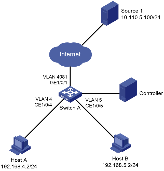
As shown in Figure 1, Switch A receives traffic from video source Source 1 on Internet. Configure the OVS controller to deploy OpenFlow flow entries and group entries to meet the following requirements:
· Switch A translates the public network address to a private network address for a packet received from Source 1 in VLAN 4081. Switch A sets the destination IP, destination MAC, and destination UDP port number of a packet according to the target host IP.
· Switch A sends the NATed packets to Host A and Host B on the private network.
|
Device name |
MAC |
IP |
UDP |
|
Source 1 |
00:02:fc:00:22:2b |
11.110.5.100 |
6457 |
|
Host A |
00:e0:4c:68:0e:d4 |
192.168.4.2 |
4488 |
|
Host B |
00:50:56:c0:00:08 |
192.168.5.2 |
2356 |
Analysis
· Make sure Switch A and the controller can reach each other so that the OpenFlow instance can establish an OpenFlow channel with the controller. In this example, Switch A uses the management interface to communicate with the controller.
· For the receiver hosts to receive traffic from the source, configure the controller to issue the OpenFlow flow entry and group entry that meet the following requirements:
¡ Switch A can use the flow entry to match packets from Source 1.
¡ Switch A can use the group entry to change the VLAN ID, destination IP address, destination MAC address, and destination UDP port number of the matching packets to those of Host A and Host B.
¡ Switch A can use the group entry to forward the matching packets out of GigabitEthernet 1/0/4 and GigabitEthernet 1/0/5.
Applicable hardware and software versions
The following matrix shows the hardware and software versions to which this configuration example is applicable:
|
Hardware |
Software version |
|
S6812 switch series S6813 switch series |
Not supported |
|
S6550XE-HI switch series |
Release 8106Pxx |
|
S6525XE-HI switch series |
Not supported |
|
S5850 switch series |
Not supported |
|
S5570S-EI switch series |
Not supported |
|
S5560X-EI switch series |
Not supported |
|
S5560X-HI switch series |
Not supported |
|
S5500V2-EI switch series |
Not supported |
|
MS4520V2-30F switch |
Not supported |
|
MS4520V2-30C switch MS4520V2-54C switch |
Not supported |
|
MS4520V2-28S switch MS4520V2-24TP switch |
Not supported |
|
S6520X-HI switch series S6520X-EI switch series |
Not supported |
|
S6520X-SI switch series S6520-SI switch series |
Not supported |
|
S5000-EI switch series |
Not supported |
|
MS4600 switch series |
Not supported |
|
ES5500 switch series |
Not supported |
|
S5560S-EI switch series S5560S-SI switch series |
Not supported |
|
S5500V3-24P-SI switch S5500V3-48P-SI switch |
Not supported |
|
S5500V3-SI switch series (except S5500V3-24P-SI and S5500V3-48P-SI) |
Not supported |
|
S5170-EI switch series |
Not supported |
|
S5130S-HI switch series S5130S-EI switch series S5130S-SI switch series S5130S-LI switch series |
Not supported |
|
S5120V2-SI switch series S5120V2-LI switch series |
Not supported |
|
S5120V3-EI switch series |
Not supported |
|
S5120V3-36F-SI switch S5120V3-28P-HPWR-SI switch S5120V3-54P-PWR-SI switch |
Not supported |
|
S5120V3-SI switch series (except S5120V3-36F-SI, S5120V3-28P-HPWR-SI, and S5120V3-54P-PWR-SI) |
Not supported |
|
S5120V3-LI switch series |
Not supported |
|
S3600V3-EI switch series |
Not supported |
|
S3100V3-EI switch series S3100V3-SI switch series |
Not supported |
|
S5110V2 switch series |
Not supported |
|
S5110V2-SI switch series |
Not supported |
|
S5000V3-EI switch series S5000V5-EI switch series |
Not supported |
|
S5000E-X switch series S5000X-EI switch series |
Not supported |
|
E128C switch E152C switch E500C switch series E500D switch series |
Not supported |
|
MS4320V2 switch series MS4320V3 switch series MS4300V2 switch series MS4320 switch series MS4200 switch series |
Not supported |
|
WS5850-WiNet switch series |
Not supported |
|
WS5820-WiNet switch series WS5810-WiNet switch series |
Not supported |
|
WAS6000 switch series |
Not supported |
|
IE4300-12P-AC switch IE4300-12P-PWR switch IE4300-M switch series IE4320 switch series |
Not supported |
|
IE4520 switch series |
Not supported |
|
S5135S-EI switch series |
Not supported |
Procedures
Configuring Switch A
# Create VLANs. Assign Ethernet interfaces to VLANs as needed.
<SwitchA> system-view
[SwitchA] vlan 4 5 4081
[SwitchA] interface gigabitethernet 1/0/1
[SwitchA-GigabitEthernet1/0/1] port link-type trunk
[SwitchA-GigabitEthernet1/0/1] port trunk permit vlan 4081
[SwitchA-GigabitEthernet1/0/1] quit
[SwitchA] interface gigabitethernet 1/0/4
[SwitchA-GigabitEthernet1/0/4] port link-type trunk
[SwitchA-GigabitEthernet1/0/4] port trunk permit vlan 4
[SwitchA-GigabitEthernet1/0/4] quit
[SwitchA] interface gigabitethernet 1/0/5
[SwitchA-GigabitEthernet1/0/5] port link-type trunk
[SwitchA-GigabitEthernet1/0/5] port trunk permit vlan 5
[SwitchA-GigabitEthernet1/0/5] quit
# Configure M-GigabitEthernet 0/0/0 on Switch A for communicating with the controller.
[SwitchA] interface M-GigabitEthernet 0/0/0
[SwitchA-M-GigabitEthernet0/0/0] ip address 172.16.147.136 255.255.0.0
[SwitchA-M-GigabitEthernet0/0/0] quit
# Create OpenFlow instance 1 and configure it to operate in global mode.
[SwitchA] openflow instance 1
[SwitchA-of-inst-1] classification global
# Specify controller 0 with IP address 172.16.147.101 for OpenFlow instance 1 and activate the instance.
[SwitchA-of-inst-1] controller 0 address ip 172.16.147.101
[SwitchA-of-inst-1] active instance
[SwitchA-of-inst-1] quit
Configuring the OVS controller
# Create group entry 1 that contains the following buckets to OpenFlow instance 1:
· Bucket 1 that contains the following actions:
¡ Send the packets out of GigabitEthernet 1/0/4.
¡ Change the following fields in the packets: VLAN ID (4), destination IP address (192.168.4.2), destination MAC address (00:e0:4c:68:0e:d4), and destination UDP port number (4488).
· Bucket 2 that contains the following actions:
¡ Send the packets out of GigabitEthernet 1/0/5.
¡ Change the following fields in the packets: VLAN ID (5), destination IP address (192.168.5.2), destination MAC address (00:50:56:c0:00:08), and destination UDP port number (2356).
[root@openflowvm:~/controller0]# ./ovs-appctl send_group_str 'command(add),type(
all),group_id(1),bucket(actions(output(742),set_field(vlan_vid(4+1)),set_field(eth_dst(00:e0:4c:68:0e:d4)),set_field(ipv4_dst(192.168.4.2)),set_field(udp_dst(4488)))),bucket(actions(output(743),set_field(vlan_vid(5+1)),set_field(eth_dst(00:50:56:c0:00:08)),set_field(ipv4_dst(192.168.5.2)),set_field(udp_dst(2356))))'
22:46:56|tcp:172.16.147.136:4425: sent (Success): OFPT_GROUP_MOD (xid:31, len:16
0)
22:46:56|OFPT_GROUP_MOD (xid:31)
# Group_Mod
|- command = add
|- type = all
|- group_id = 1
|- bucket
|- weight = 0
|- watch_port = any
|- watch_group = any
|- actions
|- output,742 [max_len = 128]
|- set_field,vlan_vid,4+1
|- set_field,eth_dst,00:e0:4c:68:0e:d4
|- set_field,ipv4_dst,192.168.4.2
|- set_field,udp_dst,4488
|- bucket
|- weight = 0
|- watch_port = any
|- watch_group = any
|- actions
|- output,743 [max_len = 128]
|- set_field,vlan_vid,5+1
|- set_field,eth_dst,00:50:56:c0:00:08
|- set_field,ipv4_dst,192.168.5.2
|- set_field,udp_dst,2356
[root@openflowvm:~/controller0]#
# Issue flow entry 1 of table 0 to OpenFlow instance 1. The flow entry contains the following match fields: input port GigabitEthernet 1/0/1, VLAN ID 4081, source IP address 10.110.5.100, source MAC address 00:02:fc:00:22:2b, and source UDP port 6457. Group entry 1 is specified to process the matching packets.
[root@openflowvm:~/controller0]# ./ovs-appctl send_flow_str 'command(add),table_
id(0),priority(1),match(in_port(739),vlan_vid(4081+1),eth_src(00:02:fc:00:22:2b),eth_type(0x800),ipv4_src(10.110.5.100),ip_proto(17),udp_src(6457)),instruction(write_actions(group(1)))'
23:08:24|tcp:172.16.147.136:4425: sent (Success): OFPT_FLOW_MOD (xid:35, len:120
)
23:08:24|OFPT_FLOW_MOD (xid:35)
# Flow_Mod (48)
|- cookie = 0x0000000000000000
|- cookie_mask = 0x0000000000000000
|- table_id = 0
|- command = add
|- idle_timeout = 0
|- hard_timeout = 0
|- priority = 1
|- buffer_id = no_buffer
|- out_port = any
|- out_group = any
|- flags = 0
|- match
|- in_port,739
|- vlan_vid,4081+1
|- eth_src,00:02:fc:00:22:2b
|- eth_type,0x0800
|- ipv4_src,10.110.5.100
|- ip_proto,17
|- udp_src,6457
|- instructions
|- write_actions
|- group,1
[root@openflowvm:~/controller0]#
Verifying the configuration
Verify the configuration on Switch A.
# Display group entry information for OpenFlow instance 1 on Switch A.
[SwitchA] display openflow instance 1 group
Instance 1 group table information:
Group count: 1
Group entry 1:
Type: All, byte count: 0, packet count: 0
Bucket 1 information:
Action count 2, watch port: any, watch group: any
Byte count 0, packet count 0
Set field:
Ethernet destination MAC address: 00e0-4c68-0ed4
VLAN ID: 4
IPv4 destination address: 192.168.4.2
UDP destination port: 4488
Output interface: GE1/0/4
Bucket 2 information:
Action count 2, watch port: any, watch group: any
Byte count 0, packet count 0
Set field:
Ethernet destination MAC address: 0050-56c0-0008
VLAN ID: 5
IPv4 destination address: 192.168.5.2
UDP destination port: 2356
Output interface: GE1/0/5
Referenced information:
Count: 1
Flow table: 0
Flow entry: 1
The output shows that OpenFlow instance 1 has created the group entry issued by the OVS controller. Group entry 1 is configured to set the specified fields in matching packets and send the modified packets out of GigabitEthernet 1/0/4 and GigabitEthernet 1/0/5.
[SwitchA] display openflow instance 1 flow
Instance 1 flow table information:
Table 0 information:
Table type: Extensibility, flow entry count: 1, total flow entry count: 2
MissRule (default) flow entry information:
cookie: 0x0, priority: 0, hard time: 0, idle time: 0, flags: reset_counts,
byte count: 383689, packet count: 3330
Create time:19:07:20 01/06/2019, Last modified time:19:07:20 01/06/2019
Match information: any
Instruction information:
Write actions:
Drop
Flow entry 1 information:
cookie: 0x0, priority: 1, hard time: 0, idle time: 0, flags: none,
byte count: 0, packet count: 0
Create time:19:30:33 01/06/2019, Last modified time:19:30:33 01/06/2019
Match information:
Input interface: GE1/0/1
Ethernet source MAC address: 0002-fc00-222b
Ethernet source MAC address mask: ffff-ffff-ffff
Ethernet type: 0x0800
VLAN ID: 4081, mask: 0xfff
IP protocol: 17
IPv4 source address: 10.110.5.100, mask: 255.255.255.255
UDP source port: 6457, mask: 0xffff
Instruction information:
Write actions:
Group: 1
The output shows that OpenFlow instance 1 has created the flow entry issued by the OVS controller in table 0. The instance will use the flow entry to match packets from Source 1 and use group entry 1 to process the matching packets.
Configuration files
· Switch A:
#
interface M-GigabitEthernet0/0/0
ip address 172.16.147.136 255.255.0.0
#
openflow instance 1
classification global
controller 0 address ip 172.16.147.101
active instance
#
interface GigabitEthernet1/0/1
port link-mode bridge
port link-type trunk
port trunk permit vlan 1 4081
#
interface GigabitEthernet1/0/4
port link-mode bridge
port link-type trunk
port trunk permit vlan 1 4
#
interface GigabitEthernet1/0/5
port link-mode bridge
port link-type trunk
port trunk permit vlan 1 5
#
