- Table of Contents
-
- H3C Fixed Port Campus Switches Configuration Examples-6W105
- 00-Applicable hardware and software versions
- 01-Login Management Configuration Examples
- 02-RBAC Configuration Examples
- 03-Software Upgrade Examples
- 04-ISSU Configuration Examples
- 05-Software Patching Examples
- 06-Ethernet Link Aggregation Configuration Examples
- 07-Port Isolation Configuration Examples
- 08-Spanning Tree Configuration Examples
- 09-VLAN Configuration Examples
- 10-VLAN Tagging Configuration Examples
- 11-DHCP Snooping Configuration Examples
- 12-Cross-Subnet Dynamic IP Address Allocation Configuration Examples
- 13-IPv6 over IPv4 Tunneling with OSPFv3 Configuration Examples
- 14-IPv6 over IPv4 GRE Tunnel Configuration Examples
- 15-GRE with OSPF Configuration Examples
- 16-OSPF Configuration Examples
- 17-IS-IS Configuration Examples
- 18-BGP Configuration Examples
- 19-Policy-Based Routing Configuration Examples
- 20-OSPFv3 Configuration Examples
- 21-IPv6 IS-IS Configuration Examples
- 22-Routing Policy Configuration Examples
- 23-IGMP Snooping Configuration Examples
- 24-IGMP Configuration Examples
- 25-MLD Snooping Configuration Examples
- 26-IPv6 Multicast VLAN Configuration Examples
- 27-ACL Configuration Examples
- 28-Traffic Policing Configuration Examples
- 29-GTS and Rate Limiting Configuration Examples
- 30-Traffic Filtering Configuration Examples
- 31-AAA Configuration Examples
- 32-Port Security Configuration Examples
- 33-Portal Configuration Examples
- 34-SSH Configuration Examples
- 35-IP Source Guard Configuration Examples
- 36-Ethernet OAM Configuration Examples
- 37-CFD Configuration Examples
- 38-DLDP Configuration Examples
- 39-VRRP Configuration Examples
- 40-BFD Configuration Examples
- 41-NTP Configuration Examples
- 42-SNMP Configuration Examples
- 43-NQA Configuration Examples
- 44-Mirroring Configuration Examples
- 45-sFlow Configuration Examples
- 46-OpenFlow Configuration Examples
- 47-MAC Address Table Configuration Examples
- 48-Static Multicast MAC Address Entry Configuration Examples
- 49-IP Unnumbered Configuration Examples
- 50-MVRP Configuration Examples
- 51-MCE Configuration Examples
- 52-Attack Protection Configuration Examples
- 53-Smart Link Configuration Examples
- 54-RRPP Configuration Examples
- 55-BGP Route Selection Configuration Examples
- 56-IS-IS Route Summarization Configuration Examples
- 57-VXLAN Configuration Examples
- 58-DRNI Configuration Examples
- 59-IRF 3.1 Configuration Examples
- 60-PTP Configuration Examples
- 61-S-MLAG Configuration Examples
- 62-Puppet Configuration Examples
- 63-802.1X Configuration Examples
- 64-MAC Authentication Configuration Examples
- 65-ISATAP Tunnel and 6to4 Tunnel Configuration Examples
- 66-BIDIR-PIM Configuration Examples
- 67-Congestion Avoidance and Queue Scheduling Configuration Examples
- 68-Basic MPLS Configuration Examples
- 69-MPLS L3VPN Configuration Examples
- 70-MPLS OAM Configuration Examples
- 71-EVPN-DCI over an MPLS L3VPN Network Configuration Examples
- 72-DRNI and EVPN Configuration Examples
- 73-Multicast VPN Configuration Examples
- 74-MPLS TE Configuration Examples
- 75-Control Plane-Based QoS Policy Configuration Examples
- 76-Priority Mapping and Queue Scheduling Configuration Examples
- 77-ARP Attack Protection Configuration Examples
- 78-IRF Software Upgrade Configuration Examples
- 79-IRF Member Replacement Configuration Examples
- 80-Layer 3 Multicast on Multicast Source-Side DR System Configuration Examples
- 81-EVPN Multicast Configuration Examples
- 82-Priority Marking and Queue Scheduling Configuration Examples
- 83-EAA Configuration Examples
- 84-GRE Tunnel Access to MPLS L3VPN Configuration Examples
- 85-MC-NAT Configuration Examples
- 86-M-LAG Configuration Examples (Applicable to M-LAG Versions)
- 87-MOD Configuration Examples
- 88-MPLS L2VPN Configuration Examples
- 89-VPLS Configuration Examples
- 90-SR-MPLS Configuration Examples
- 91-VCF Fabric Configuration Examples
- 92-NetStream Configuration Examples
- 93-Configuration Example for Software Upgrade with Zero Packet Loss by Using GIR in VXLAN M-LAG Network
- 94-Configuration Example for Software Upgrade with Zero Packet Loss by Using GIR in VXLAN DRNI Network
- Related Documents
-
89-VPLS Configuration Examples
Example: Configuring full-mesh VPLS (LDP signaling)
Applicable hardware and software versions
Example: Configuring full-mesh VPLS (BGP auto-discovery LDP signaling)
Applicable hardware and software versions
Example: Configuring full-mesh VPLS (BGP)
Applicable hardware and software versions
Example: Configuring H-VPLS (LSP access)
Applicable hardware and software versions
Example: Configuring H-VPLS (QinQ access)
Applicable hardware and software versions
Overview
Virtual Private LAN Service (VPLS) delivers a point-to-multipoint L2VPN service over an MPLS or IP backbone. The provider backbone emulates a switch to connect all geographically dispersed sites of each customer network. The backbone is transparent to the customer sites. The sites can communicate with each other as if they were on the same LAN.
VPLS has the following networking models:
· Full mesh—Suitable for MPLS backbone networks with a simple architecture and fewer PEs. The following networking modes are available under this model:
¡ LDP—Uses the LDP protocol as the signaling protocol, suitable for scenarios with a small number of sites and the number of sites is fixed.
¡ BGP auto-discovery with LDP signaling—Uses the BGP protocol to automatically discover remote PEs, and then uses the LDP protocol as the signaling protocol, suitable for scenarios with many sites but the number of sites is fixed.
¡ BGP—Uses extended BGP as the signaling protocol, suitable for scenarios with a large number of sites and the need for expansion.
· H-VPLS—Suitable for MPLS backbone networks with a complex architecture and a large number of PEs. This model uses a hierarchical network structure that contains UPEs and NPEs. A UPE is responsible for customer site access and establishing connections with the nearest NPE, and NPEs are fully interconnected logically. UPEs exchange packets with remote sites through NPEs. The following networking modes are available under this model:
¡ LSP access—Packets are transmitted over an LSP tunnel, suitable for scenarios where UPEs support VPLS.
¡ QinQ access—Packets are encapsulated with an outer VLAN tag before being transmitted over an LSP tunnel, suitable for scenarios where UPE devices do not support VPLS.
Prerequisites
The configuration examples were created and verified in a lab environment, and all the devices were started with the factory default configuration. When you are working on a live network, make sure you understand the potential impact of every command on your network.
The following information is provided based on the assumption that you have basic knowledge of VPLS.
Restrictions and guidelines
Before you configure MPLS, you must change the device's operating mode by using the switch-mode command and restart the device for the following switches:
· S6812 series
· S6813 series
· S5560X-EI series
· S5560X-HI series
· S5500V2-EI series
· MS4520V2-30F
· MS4520V2-30C
· MS4520V2-54C
· S6520X-HI series
· S6520X-EI series
· S6520X-SI series
· S6520-SI series
· S5000-EI series
· MS4600 series
In a non-IRF environment, use the switch-mode 3 command to switch the device to MPLS mode.
In an IRF environment, use the switch-mode 4 command to switch the device to MPLS-IRF mode.
PEs do not transparently transmit LACP or LLDP protocol packets over a VPLS network.
If STP is globally enabled on a PE, the PE transparently transmits STP packets over the VPLS network only after you use the stp transparent enable command to enable BPDU transparent transmission on a port. For more information about the stp transparent enable command, see STP commands in Layer 2—LAN Switching Command Reference.
Example: Configuring full-mesh VPLS (LDP signaling)
Network configuration
As shown in Figure 1, a company has three offices in different locations: headquarters and two branches. The company requires the provider to offer a Layer 2 VPN service that interconnects the three offices at Layer 2, allowing them to share internal resources.
The company has few branches and will not expand further. To meet user requirements, configure LDP-based VPLS to enable communication between the three sites at Layer 2.
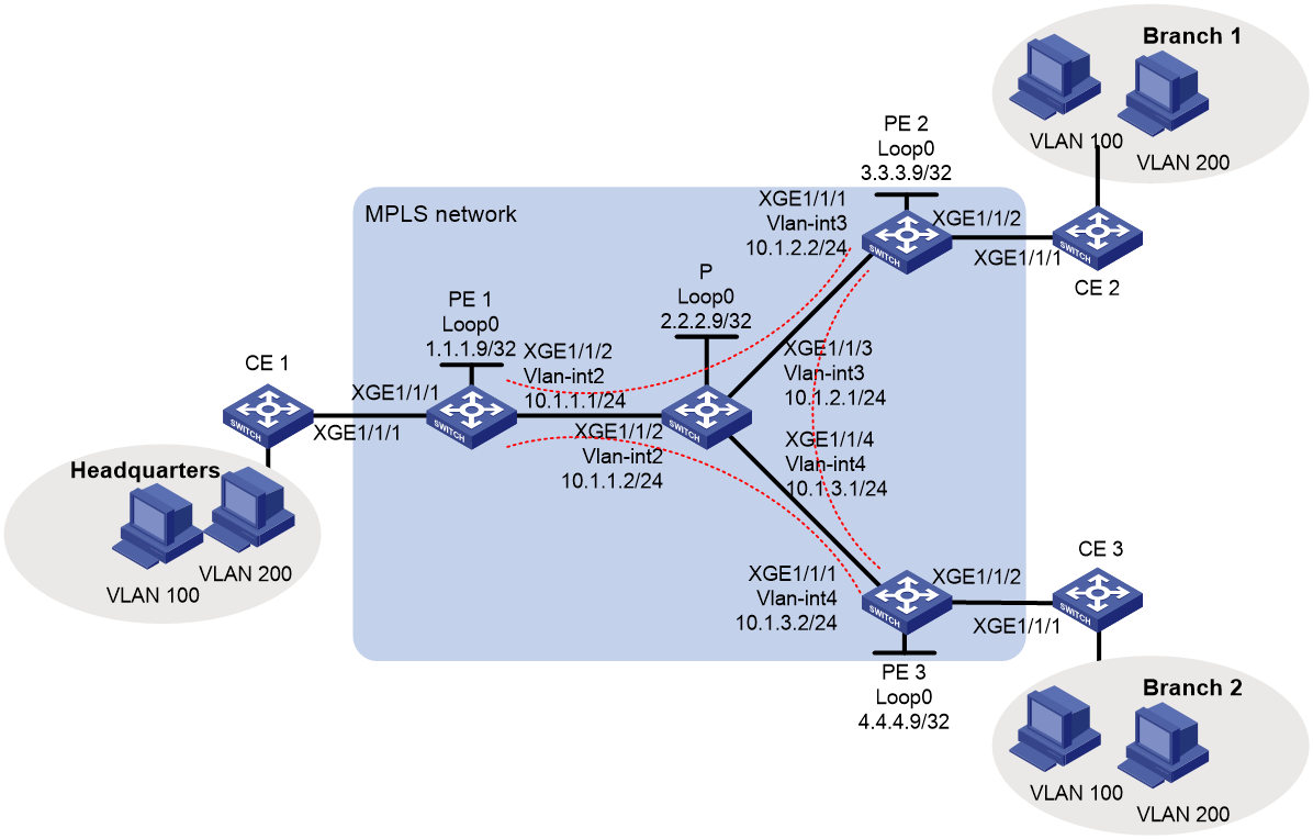
Analysis
· Deploy MPLS on the backbone network and use LSP as the public tunnel.
· Establish LDP PWs between the PEs for full-mesh VPLS.
· Configure a service instance and corresponding match rules on the downlink port of each PE device to identify packets from the customer network that require a VPLS tunnel for transmission.
· To achieve VLAN isolation between sites, create VSIs user_a and user_b and bind them to VLAN 100 and VLAN 200, respectively.
Applicable hardware and software versions
Table 1 Applicable hardware and software versions
|
Hardware |
Software version |
|
S6812 series S6813 series |
Release 6628Pxx series |
|
S6550XE-HI series |
Release 8106Pxx |
|
S6525XE-HI series |
Release 8106Pxx |
|
S5850 series |
Unsupported |
|
S5570S-EI series |
Unsupported |
|
S5560X-EI series |
Release 6628Pxx |
|
S5560X-HI series |
Release 6628Pxx |
|
S5500V2-EI series |
Release 6628Pxx series |
|
MS4520V2-30F |
Release 6628Pxx series |
|
MS4520V2-30C MS4520V2-54C |
Release 6628Pxx series |
|
MS4520V2-28S MS4520V2-24TP |
Unsupported |
|
S6520X-HI series S6520X-EI series |
Release 6628Pxx series |
|
S6520X-SI series S6520-SI series |
Release 6628Pxx series |
|
S5000-EI series |
Release 6628Pxx series |
|
MS4600 series |
Release 6628Pxx series |
|
ES5500 series |
Release 6628Pxx series |
|
S5560S-EI series S5560S-SI series |
Unsupported |
|
S5500V3-24P-SI S5500V3-48P-SI |
Unsupported |
|
S5500V3-SI series (excluding the S5500V3-24P-SI and S5500V3-48P-SI) |
Unsupported |
|
S5170-EI series |
Unsupported |
|
S5130S-HI series S5130S-EI series S5130S-SI series S5130S-LI series |
Unsupported |
|
S5120V2-SI series S5120V2-LI Series |
Unsupported |
|
S5120V3-EI series |
Unsupported |
|
S5120V3-36F-SI S5120V3-28P-HPWR-SI S5120V3-54P-PWR-SI |
Unsupported |
|
S5120V3-SI series (excluding S5120V3-36F-SI, S5120V3-28P-HPWR-SI, and S5120V3-54P-PWR-SI) |
Unsupported |
|
S5120V3-LI series |
Unsupported |
|
S3600V3-EI series |
Unsupported |
|
S3600V3-SI series |
Unsupported |
|
S3100V3-EI series S3100V3-SI series |
Unsupported |
|
S5110V2 series |
Unsupported |
|
S5110V2-SI series |
Unsupported |
|
S5000V3-EI series S5000V5-EI series |
Unsupported |
|
S5000E-X series S5000X-EI series |
Unsupported |
|
E128C E152C E500C series E500D series |
Unsupported |
|
MS4320V2 series MS4320V3 series MS4300V2 series MS4320 series MS4200 series |
Unsupported |
|
WS5850-WiNet series |
Unsupported |
|
WS5820-WiNet series WS5810-WiNet series |
Unsupported |
|
WAS6000 series |
Unsupported |
|
IE4300-12P-AC & IE4300-12P-PWR IE4300-M series IE4320 series |
Unsupported |
|
S5135S-EI series |
Unsupported |
Procedure
Configuring IGP on the MPLS backbone network to enable communication between PEs and P devices on the backbone network
· Configure PE 1:
# Configure a loopback interface address.
<PE1> system-view
[PE1] interface loopback 0
[PE1-LoopBack0] ip address 1.1.1.9 32
[PE1-LoopBack0] quit
# Create VLAN 2 and add Ten-GigabitEthernet 1/0/2 to VLAN 2.
[PE1] vlan 2
[PE1-vlan2] port ten-gigabitethernet 1/0/2
[PE1-vlan2] quit
# Create VLAN-interface 2.
[PE1] interface vlan-interface 2
[PE1-Vlan-interface2] ip address 10.1.1.1 24
[PE1-Vlan-interface2] quit
# Configure OSPF on PE 1 for establishing LSPs.
[PE1] ospf
[PE1-ospf-1] area 0
[PE1-ospf-1-area-0.0.0.0] network 10.1.1.0 0.0.0.255
[PE1-ospf-1-area-0.0.0.0] network 1.1.1.9 0.0.0.0
[PE1-ospf-1-area-0.0.0.0] quit
[PE1-ospf-1] quit
· Configure PE 2:
# Configure a loopback interface address.
<PE2> system-view
[PE2] interface loopback 0
[PE2-LoopBack0] ip address 3.3.3.9 32
[PE2-LoopBack0] quit
# Create VLAN 3 and add Ten-GigabitEthernet 1/0/1 to VLAN 3.
[PE2] vlan 3
[PE2-vlan3] port ten-gigabitethernet 1/0/1
[PE2-vlan3] quit
# Create VLAN-interface 3.
[PE2] interface vlan-interface 3
[PE2-Vlan-interface3] ip address 10.1.2.2 24
[PE2-Vlan-interface3] quit
# Configure OSPF on PE 2 for establishing LSPs.
[PE2] ospf
[PE2-ospf-1] area 0
[PE2-ospf-1-area-0.0.0.0] network 10.1.2.0 0.0.0.255
[PE2-ospf-1-area-0.0.0.0] network 3.3.3.9 0.0.0.0
[PE2-ospf-1-area-0.0.0.0] quit
[PE2-ospf-1] quit
· Configure PE 3:
# Configure a loopback interface address.
<PE3> system-view
[PE3] interface loopback 0
[PE3-LoopBack0] ip address 4.4.4.9 32
[PE3-LoopBack0] quit
# Create VLAN 4 and add Ten-GigabitEthernet 1/0/1 to VLAN 4.
[PE3] vlan 4
[PE3-vlan4] port ten-gigabitethernet 1/0/1
[PE3-vlan4] quit
# Create VLAN-interface 4.
[PE3] interface vlan-interface 4
[PE3-Vlan-interface4] ip address 10.1.3.2 24
[PE3-Vlan-interface4] quit
# Configure OSPF on PE 3 for establishing LSPs.
[PE3] ospf
[PE3-ospf-1] area 0
[PE3-ospf-1-area-0.0.0.0] network 10.1.3.0 0.0.0.255
[PE3-ospf-1-area-0.0.0.0] network 4.4.4.9 0.0.0.0
[PE3-ospf-1-area-0.0.0.0] quit
[PE3-ospf-1] quit
· Configure the P device:
# Configure a loopback interface address.
<P> system-view
[P] interface loopback 0
[P-LoopBack0] ip address 2.2.2.9 32
[P-LoopBack0] quit
# Create VLAN 2 and add Ten-GigabitEthernet 1/0/2 to VLAN 2.
[P] vlan 2
[P-vlan2] port ten-gigabitethernet 1/0/2
[P-vlan2] quit
# Configure VLAN-interface 2.
[P] interface vlan-interface 2
[P-Vlan-interface2] ip address 10.1.1.2 24
[P-Vlan-interface2] quit
# Create VLAN 3 and add Ten-GigabitEthernet 3/0/1 to VLAN 3.
[P] vlan 3
[P-vlan3] port ten-gigabitethernet 1/0/3
[P-vlan3] quit
# Configure VLAN-interface 3.
[P] interface vlan-interface 3
[P-Vlan-interface3] ip address 10.1.2.1 24
[P-Vlan-interface3] quit
# Create VLAN 4 and add Ten-GigabitEthernet 1/0/4 to VLAN 4.
[P] vlan 4
[P-vlan4] port ten-gigabitethernet 1/0/4
[P-vlan4] quit
# Configure VLAN-interface 4.
[P] interface vlan-interface 4
[P-Vlan-interface4] ip address 10.1.3.1 24
[P-Vlan-interface4] quit
# Configure OSPF on the P device for establishing LSPs.
[P] ospf
[P-ospf-1] area 0
[P-ospf-1-area-0.0.0.0] network 10.1.1.0 0.0.0.255
[P-ospf-1-area-0.0.0.0] network 10.1.2.0 0.0.0.255
[P-ospf-1-area-0.0.0.0] network 10.1.3.0 0.0.0.255
[P-ospf-1-area-0.0.0.0] network 2.2.2.9 0.0.0.0
[P-ospf-1-area-0.0.0.0] quit
[P-ospf-1] quit
Configuring basic MPLS and MPLS LDP on the MPLS backbone network to establish LDP LSPs
· Configure PE 1:
# Configure an LSR ID.
[PE1] mpls lsr-id 1.1.1.9
# Enable LDP globally.
[PE1] mpls ldp
[PE1-ldp] quit
# Enable MPLS and LDP VLAN-interface 2.
[PE1] interface vlan-interface 2
[PE1-Vlan-interface2] mpls enable
[PE1-Vlan-interface2] mpls ldp enable
[PE1-Vlan-interface2] quit
· Configure PE 2:
# Configure an LSR ID.
[PE2] mpls lsr-id 3.3.3.9
# Enable LDP globally.
[PE2] mpls ldp
[PE2-ldp] quit
# Enable MPLS and LDP on VLAN-interface 3.
[PE2] interface vlan-interface 3
[PE2-Vlan-interface3] mpls enable
[PE2-Vlan-interface3] mpls ldp enable
[PE2-Vlan-interface3] quit
· Configure PE 3:
# Configure an LSR ID.
[PE3] mpls lsr-id 4.4.4.9
# Enable LDP globally.
[PE3] mpls ldp
[PE3-ldp] quit
# Enable MPLS and LDP on VLAN-interface 4.
[PE3] interface vlan-interface 4
[PE3-Vlan-interface4] mpls enable
[PE3-Vlan-interface4] mpls ldp enable
[PE3-Vlan-interface4] quit
· Configure the P device:
# Configure an LSR ID.
[P] mpls lsr-id 2.2.2.9
# Enable LDP globally.
[P] mpls ldp
[P-ldp] quit
# Enable MPLS and LDP VLAN-interface 2.
[P] interface vlan-interface 2
[P-Vlan-interface2] mpls enable
[P-Vlan-interface2] mpls ldp enable
[P-Vlan-interface2] quit
# Enable MPLS and LDP on VLAN-interface 3.
[P] interface vlan-interface 3
[P-Vlan-interface3] mpls enable
[P-Vlan-interface3] mpls ldp enable
[P-Vlan-interface3] quit
# Enable MPLS and LDP on VLAN-interface 4.
[P] interface vlan-interface 4
[P-Vlan-interface4] mpls enable
[P-Vlan-interface4] mpls ldp enable
[P-Vlan-interface4] quit
Creating a VSI and configuring LDP PWs
· Configure PE 1:
# Enable MPLS L2VPN globally.
[PE1] l2vpn enable
# Configure VSI user_a that uses LDP as the PW signaling protocol.
[PE1] vsi user_a
[PE1-vsi-user_a] pwsignaling ldp
# Establish PWs to PE 2 and PE 3.
[PE1-vsi-user_a-ldp] peer 3.3.3.9 pw-id 500
[PE1-vsi-user_a-ldp-3.3.3.9-500] quit
[PE1-vsi-user_a-ldp] peer 4.4.4.9 pw-id 500
[PE1-vsi-user_a-ldp-4.4.4.9-500] quit
[PE1-vsi-user_a-ldp] quit
[PE1-vsi-user_a] quit
# Configure VSI user_b that uses LDP as the PW signaling protocol.
[PE1] vsi user_b
[PE1-vsi-user_b] pwsignaling ldp
# Establish PWs to PE 2 and PE 3.
[PE1-vsi-user_b-ldp] peer 3.3.3.9 pw-id 600
[PE1-vsi-user_b-ldp-3.3.3.9-600] quit
[PE1-vsi-user_b-ldp] peer 4.4.4.9 pw-id 600
[PE1-vsi-user_b-ldp-4.4.4.9-600] quit
[PE1-vsi-user_b-ldp] quit
[PE1-vsi-user_b] quit
· Configure PE 2:
# Enable MPLS L2VPN globally.
[PE2] l2vpn enable
# Configure VSI user_a that uses LDP as the PW signaling protocol.
[PE2] vsi user_a
[PE2-vsi-user_a] pwsignaling ldp
# Establish PWs to PE 1 and PE 3.
[PE2-vsi-user_a-ldp] peer 1.1.1.9 pw-id 500
[PE2-vsi-user_a-ldp-1.1.1.9-500] quit
[PE2-vsi-user_a-ldp] peer 4.4.4.9 pw-id 500
[PE2-vsi-user_a-ldp-4.4.4.9-500] quit
[PE2-vsi-user_a-ldp] quit
[PE2-vsi-user_a] quit
# Configure VSI user_b that uses LDP as the PW signaling protocol.
[PE2] vsi user_b
[PE2-vsi-user_b] pwsignaling ldp
# Establish PWs to PE 1 and PE 3.
[PE2-vsi-user_b-ldp] peer 1.1.1.9 pw-id 600
[PE2-vsi-user_b-ldp-1.1.1.9-600] quit
[PE2-vsi-user_b-ldp] peer 4.4.4.9 pw-id 600
[PE2-vsi-user_b-ldp-4.4.4.9-600] quit
[PE2-vsi-user_b-ldp] quit
[PE2-vsi-user_b] quit
· Configure PE 3:
# Enable MPLS L2VPN globally.
[PE3] l2vpn enable
# Configure VSI user_a that uses LDP as the PW signaling protocol.
[PE3] vsi user_a
[PE3-vsi-user_a] pwsignaling ldp
# Establish PWs to PE 1 and PE 2.
[PE3-vsi-user_a-ldp] peer 1.1.1.9 pw-id 500
[PE3-vsi-user_a-ldp-1.1.1.9-500] quit
[PE3-vsi-user_a-ldp] peer 3.3.3.9 pw-id 500
[PE3-vsi-user_a-ldp-3.3.3.9-500] quit
[PE3-vsi-user_a-ldp] quit
[PE3-vsi-user_a] quit
# Configure VSI user_b that uses LDP as the PW signaling protocol.
[PE3] vsi user_b
[PE3-vsi-user_b] pwsignaling ldp
# Establish PWs to PE 1 and PE 2.
[PE3-vsi-user_b-ldp] peer 1.1.1.9 pw-id 600
[PE3-vsi-user_b-ldp-1.1.1.9-600] quit
[PE3-vsi-user_b-ldp] peer 3.3.3.9 pw-id 600
[PE3-vsi-user_b-ldp-3.3.3.9-600] quit
[PE3-vsi-user_b-ldp] quit
[PE3-vsi-user_b] quit
Configuring service instances for data from different VLANs and bind them to different VSIs
· Configure PE 1:
# Create service instance 100 on Ten-GigabitEthernet 1/0/1 to match packets from VLAN 100, and bind it to VSI instance user_a.
[PE1] interface ten-gigabitethernet 1/0/1
[PE1-Ten-GigabitEthernet1/0/1] service-instance 100
[PE1-Ten-GigabitEthernet1/0/1-srv100] encapsulation s-vid 100
[PE1-Ten-GigabitEthernet1/0/1-srv100] xconnect vsi user_a
[PE1-Ten-GigabitEthernet1/0/1-srv100] quit
# Create service instance 200 on Ten-GigabitEthernet 1/0/1 to match packets from VLAN 200, and bind it to VSI instance user_b.
[PE1-Ten-GigabitEthernet1/0/1] service-instance 200
[PE1-Ten-GigabitEthernet1/0/1-srv200] encapsulation s-vid 200
[PE1-Ten-GigabitEthernet1/0/1-srv200] xconnect vsi user_b
[PE1-Ten-GigabitEthernet1/0/1-srv200] quit
[PE1-Ten-GigabitEthernet1/0/1] quit
· Configure PE 2:
# Create service instance 100 on Ten-GigabitEthernet 2/0/2 to match packets from VLAN 100, and bind it to VSI instance user_a.
[PE2] interface ten-gigabitethernet 1/0/2
[PE2-Ten-GigabitEthernet1/0/2] service-instance 100
[PE2-Ten-GigabitEthernet1/0/2-srv100] encapsulation s-vid 100
[PE2-Ten-GigabitEthernet1/0/2-srv100] xconnect vsi user_a
[PE2-Ten-GigabitEthernet1/0/2-srv100] quit
# Create service instance 200 on Ten-GigabitEthernet 1/0/2 to match packets from VLAN 200, and bind it to VSI instance user_b.
[PE2-Ten-GigabitEthernet1/0/2] service-instance 200
[PE2-Ten-GigabitEthernet1/0/2-srv200] encapsulation s-vid 200
[PE2-Ten-GigabitEthernet1/0/2-srv200] xconnect vsi user_b
[PE2-Ten-GigabitEthernet1/0/2-srv200] quit
[PE2-Ten-GigabitEthernet1/0/2] quit
· Configure PE 3:
# Create service instance 100 on Ten-GigabitEthernet 1/0/2 to match packets from VLAN 100, and bind it to VSI instance user_a.
[PE3] interface ten-gigabitethernet 1/0/2
[PE3-Ten-GigabitEthernet1/0/2] service-instance 100
[PE3-Ten-GigabitEthernet1/0/2-srv100] encapsulation s-vid 100
[PE3-Ten-GigabitEthernet1/0/2-srv100] xconnect vsi user_a
[PE3-Ten-GigabitEthernet1/0/2-srv100] quit
# Create service instance 200 on Ten-GigabitEthernet 1/0/2 to match packets from VLAN 200, and bind it to VSI instance user_b.
[PE3-Ten-GigabitEthernet1/0/2] service-instance 200
[PE3-Ten-GigabitEthernet1/0/2-srv200] encapsulation s-vid 200
[PE3-Ten-GigabitEthernet1/0/2-srv200] xconnect vsi user_b
[PE3-Ten-GigabitEthernet1/0/2-srv200] quit
[PE3-Ten-GigabitEthernet1/0/2] quit
Connecting CEs to PEs
# Configure the uplink interface to the PE to allow tagged packets from the site to pass through. The following uses CE 1 as an example. Configure CE2 and CE2 in the same way CE1 is configured.
<CE1> system-view
[CE1] vlan 100
[CE1-vlan100] quit
[CE1] vlan 200
[CE1-vlan200] quit
[CE1] interface ten-gigabitethernet 1/0/1
[CE1-Ten-GigabitEthernet1/0/1] port link-type trunk
[CE1-Ten-GigabitEthernet1/0/1] port trunk permit vlan 100 200
Verifying the configuration
Verifying the public network LSPs
# Execute the display mpls ldp lsp command to verify that the LSPs have been established.
[PE1] display mpls ldp lsp
Status Flags: * - stale, L - liberal
Statistics:
FECs: 4 Ingress LSPs: 3 Transit LSPs: 3 Egress LSPs: 1
FEC In/Out Label Nexthop OutInterface
1.1.1.9/32 3/-
-/1151(L)
-/1151(L)
-/1151(L)
2.2.2.9/32 -/3 10.1.1.2 Vlan2
1151/3 10.1.1.2 Vlan2
-/1150(L)
-/1150(L)
3.3.3.9/32 -/1150 10.1.1.2 Vlan2
1150/1150 10.1.1.2 Vlan2
-/3(L)
-/1149(L)
4.4.4.9/32 -/1149 10.1.1.2 Vlan2
1149/1149 10.1.1.2 Vlan2
-/1149(L)
-/3(L)
Verifying PW status
# Execute the display l2vpn pw command on each PE. The output shows that a PW has been established and in up state.
[PE1] display l2vpn pw
Flags: M - main, B - backup, H - hub link, S - spoke link, N - no split horizon
Total number of PWs: 4
4 up, 0 blocked, 0 down, 0 defect, 0 idle, 0 duplicate
VSI Name: user_a
Peer PW ID/Rmt Site In/Out Label Proto Flag Link ID State
3.3.3.9 500 131198/131198 LDP M 64 Up
4.4.4.9 500 131199/1150 LDP M 65 Up
VSI Name: user_b
Peer PW ID/Rmt Site In/Out Label Proto Flag Link ID State
3.3.3.9 600 131196/131196 LDP M 64 Up
4.4.4.9 600 131197/1147 LDP M 65 Up
# Use ping to identify whether hosts within the same VLAN but at different sites can reach each other. If the ping operation succeeds, the VPLS is created successfully.
Configuration files
· PE 1
#
ospf 1
area 0.0.0.0
network 1.1.1.9 0.0.0.0
network 10.1.1.0 0.0.0.255
#
mpls lsr-id 1.1.1.9
#
vlan 2
#
mpls ldp
#
l2vpn enable
#
vsi user_a
pwsignaling ldp
peer 3.3.3.9 pw-id 500
peer 4.4.4.9 pw-id 500
vsi user_b
pwsignaling ldp
peer 3.3.3.9 pw-id 600
peer 4.4.4.9 pw-id 600
#
interface LoopBack0
ip address 1.1.1.9 255.255.255.255
#
interface Vlan-interface2
ip address 10.1.1.1 255.255.255.0
mpls enable
mpls ldp enable
#
interface Ten-GigabitEthernet1/0/1
port link-mode bridge
service-instance 100
encapsulation s-vid 100
xconnect vsi user_a
service-instance 200
encapsulation s-vid 200
xconnect vsi user_b
#
interface Ten-GigabitEthernet1/0/2
port link-mode bridge
port access vlan 2
#
· PE 2
ospf 1
area 0.0.0.0
network 10.1.2.0 0.0.0.255
network 3.3.3.9 0.0.0.0
#
mpls lsr-id 3.3.3.9
#
vlan 3
#
mpls ldp
#
l2vpn enable
#
vsi user_a
pwsignaling ldp
peer 1.1.1.9 pw-id 500
peer 4.4.4.9 pw-id 500
#
vsi user_b
pwsignaling ldp
peer 1.1.1.9 pw-id 600
peer 4.4.4.9 pw-id 600
#
interface LoopBack0
ip address 3.3.3.9 255.255.255.255
#
interface Vlan-interface3
ip address 10.1.2.2 255.255.255.0
mpls enable
mpls ldp enable
#
interface Ten-GigabitEthernet1/0/1
port link-mode bridge
port access vlan 3
#
interface Ten-GigabitEthernet1/0/2
port link-mode bridge
service-instance 100
encapsulation s-vid 100
xconnect vsi user_a
service-instance 200
encapsulation s-vid 200
xconnect vsi user_b
#
· PE 3
#
ospf 1
area 0.0.0.0
network 10.1.3.0 0.0.0.255
network 4.4.4.9 0.0.0.0
#
mpls lsr-id 4.4.4.9
#
vlan 4
#
mpls ldp
#
l2vpn enable
#
vsi user_a
pwsignaling ldp
peer 1.1.1.9 pw-id 500
peer 3.3.3.9 pw-id 500
#
vsi user_b
pwsignaling ldp
peer 1.1.1.9 pw-id 600
peer 3.3.3.9 pw-id 600
#
interface LoopBack0
ip address 4.4.4.9 255.255.255.255
#
interface Vlan-interface4
ip address 10.1.3.2 255.255.255.0
mpls enable
mpls ldp enable
#
interface Ten-GigabitEthernet1/0/1
port link-mode bridge
port access vlan 4
#
interface Ten-GigabitEthernet1/0/2
port link-mode bridge
service-instance 100
encapsulation s-vid 100
xconnect vsi user_a
service-instance 200
encapsulation s-vid 200
xconnect vsi user_b
#
· P
#
ospf 1
area 0.0.0.0
network 10.1.1.0 0.0.0.255
network 10.1.2.0 0.0.0.255
network 10.1.3.0 0.0.0.255
network 2.2.2.9 0.0.0.0
#
mpls lsr-id 2.2.2.9
#
vlan 2 to 4
#
mpls ldp
#
interface LoopBack0
ip address 2.2.2.9 255.255.255.255
#
interface Vlan-interface2
ip address 10.1.1.2 255.255.255.0
mpls enable
mpls ldp enable
#
interface Vlan-interface3
ip address 10.1.2.1 255.255.255.0
mpls enable
mpls ldp enable
#
interface Vlan-interface4
ip address 10.1.3.1 255.255.255.0
mpls enable
mpls ldp enable
#
interface Ten-GigabitEthernet1/0/2
port link-mode bridge
port access vlan 2
#
interface Ten-GigabitEthernet1/0/3
port link-mode bridge
port access vlan 3
#
interface Ten-GigabitEthernet1/0/4
port link-mode bridge
port access vlan 4
#
· CE 1 through CE 3
#
vlan 100
#
vlan 200
#
interface Ten-GigabitEthernet1/0/1
port link-mode bridge
port link-type trunk
port trunk permit vlan 100 200
#
Example: Configuring full-mesh VPLS (BGP auto-discovery LDP signaling)
Network configuration
As shown in Figure 2, a company has multiple offices in different locations: headquarters and several branches. The company requires the provider to offer a Layer 2 VPN service that interconnects all offices at Layer 2, allowing them to share internal resources.
The company has many branches and will not expand further. To meet user requirements and reduce configuration and maintenance workload, use BGP auto-discovery LDP signaling to enable Layer 2 communication between all user sites.
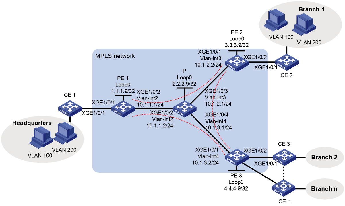
Analysis
· Deploy MPLS on the backbone network and use LSP as the public tunnel.
· Configure and establish a BGP auto-discovery LDP signaling-based PW between any two PEs to achieve full mesh of PWs.
· Configure a service instance and corresponding match rules on the downlink port of each PE device to identify packets from the customer network that require a VPLS tunnel for transmission.
· To achieve VLAN isolation between sites, create VSIs user_a and user_b and bind them to VLAN 100 and VLAN 200, respectively.
Applicable hardware and software versions
Table 2 Applicable hardware and software versions
|
Hardware |
Software version |
|
S6812 series S6813 series |
Release 6628Pxx series |
|
S6550XE-HI series |
Release 8106Pxx |
|
S6525XE-HI series |
Release 8106Pxx |
|
S5850 series |
Unsupported |
|
S5570S-EI series |
Unsupported |
|
S5560X-EI series |
Release 6628Pxx |
|
S5560X-HI series |
Release 6628Pxx |
|
S5500V2-EI series |
Release 6628Pxx series |
|
MS4520V2-30F |
Release 6628Pxx series |
|
MS4520V2-30C MS4520V2-54C |
Release 6628Pxx series |
|
MS4520V2-28S MS4520V2-24TP |
Unsupported |
|
S6520X-HI series S6520X-EI series |
Release 6628Pxx series |
|
S6520X-SI series S6520-SI series |
Release 6628Pxx series |
|
S5000-EI series |
Release 6628Pxx series |
|
MS4600 series |
Release 6628Pxx series |
|
ES5500 series |
Release 6628Pxx series |
|
S5560S-EI series S5560S-SI series |
Unsupported |
|
S5500V3-24P-SI S5500V3-48P-SI |
Unsupported |
|
S5500V3-SI series (excluding the S5500V3-24P-SI and S5500V3-48P-SI) |
Unsupported |
|
S5170-EI series |
Unsupported |
|
S5130S-HI series S5130S-EI series S5130S-SI series S5130S-LI series |
Unsupported |
|
S5120V2-SI series S5120V2-LI Series |
Unsupported |
|
S5120V3-EI series |
Unsupported |
|
S5120V3-36F-SI S5120V3-28P-HPWR-SI S5120V3-54P-PWR-SI |
Unsupported |
|
S5120V3-SI series (excluding S5120V3-36F-SI, S5120V3-28P-HPWR-SI, and S5120V3-54P-PWR-SI) |
Unsupported |
|
S5120V3-LI series |
Unsupported |
|
S3600V3-EI series |
Unsupported |
|
S3600V3-SI series |
Unsupported |
|
S3100V3-EI series S3100V3-SI series |
Unsupported |
|
S5110V2 series |
Unsupported |
|
S5110V2-SI series |
Unsupported |
|
S5000V3-EI series S5000V5-EI series |
Unsupported |
|
S5000E-X series S5000X-EI series |
Unsupported |
|
E128C E152C E500C series E500D series |
Unsupported |
|
MS4320V2 series MS4320V3 series MS4300V2 series MS4320 series MS4200 series |
Unsupported |
|
WS5850-WiNet series |
Unsupported |
|
WS5820-WiNet series WS5810-WiNet series |
Unsupported |
|
WAS6000 series |
Unsupported |
|
IE4300-12P-AC & IE4300-12P-PWR IE4300-M series IE4320 series |
Unsupported |
|
S5135S-EI series |
Unsupported |
Procedure
Configuring IGP on the MPLS backbone network to enable communication between PEs and P devices on the backbone network
· Configure PE 1:
# Configure a loopback interface address.
<PE1> system-view
[PE1] interface loopback 0
[PE1-LoopBack0] ip address 1.1.1.9 32
[PE1-LoopBack0] quit
# Create VLAN 2 and add Ten-GigabitEthernet 1/0/2 to VLAN 2.
[PE1] vlan 2
[PE1-vlan2] port ten-gigabitethernet 1/0/2
[PE1-vlan2] quit
# Create VLAN-interface 2.
[PE1] interface vlan-interface 2
[PE1-Vlan-interface2] ip address 10.1.1.1 24
[PE1-Vlan-interface2] quit
# Configure OSPF on PE 1 for establishing LSPs.
[PE1] ospf
[PE1-ospf-1] area 0
[PE1-ospf-1-area-0.0.0.0] network 10.1.1.0 0.0.0.255
[PE1-ospf-1-area-0.0.0.0] network 1.1.1.9 0.0.0.0
[PE1-ospf-1-area-0.0.0.0] quit
[PE1-ospf-1] quit
· Configure PE 2:
# Configure a loopback interface address.
<PE2> system-view
[PE2] interface loopback 0
[PE2-LoopBack0] ip address 3.3.3.9 32
[PE2-LoopBack0] quit
# Create VLAN 3 and add Ten-GigabitEthernet 1/0/1 to VLAN 3.
[PE2] vlan 3
[PE2-vlan3] port ten-gigabitethernet 1/0/1
[PE2-vlan3] quit
# Create VLAN-interface 3.
[PE2] interface vlan-interface 3
[PE2-Vlan-interface3] ip address 10.1.2.2 24
[PE2-Vlan-interface3] quit
# Configure OSPF on PE 2 for establishing LSPs.
[PE2] ospf
[PE2-ospf-1] area 0
[PE2-ospf-1-area-0.0.0.0] network 10.1.2.0 0.0.0.255
[PE2-ospf-1-area-0.0.0.0] network 3.3.3.9 0.0.0.0
[PE2-ospf-1-area-0.0.0.0] quit
[PE2-ospf-1] quit
· Configure PE 3:
# Configure a loopback interface address.
<PE3> system-view
[PE3] interface loopback 0
[PE3-LoopBack0] ip address 4.4.4.9 32
[PE3-LoopBack0] quit
# Create VLAN 4 and add Ten-GigabitEthernet 1/0/1 to VLAN 4.
[PE3] vlan 4
[PE3-vlan4] port ten-gigabitethernet 1/0/1
[PE3-vlan4] quit
# Create VLAN-interface 4.
[PE3] interface vlan-interface 4
[PE3-Vlan-interface4] ip address 10.1.3.2 24
[PE3-Vlan-interface4] quit
# Configure OSPF on PE 3 for establishing LSPs.
[PE3] ospf
[PE3-ospf-1] area 0
[PE3-ospf-1-area-0.0.0.0] network 10.1.3.0 0.0.0.255
[PE3-ospf-1-area-0.0.0.0] network 4.4.4.9 0.0.0.0
[PE3-ospf-1-area-0.0.0.0] quit
[PE3-ospf-1] quit
· Configure the P device:
# Configure a loopback interface address.
<P> system-view
[P] interface loopback 0
[P-LoopBack0] ip address 2.2.2.9 32
[P-LoopBack0] quit
# Create VLAN 2 and add Ten-GigabitEthernet 1/0/2 to VLAN 2.
[P] vlan 2
[P-vlan2] port ten-gigabitethernet 1/0/2
[P-vlan2] quit
# Configure VLAN-interface 2.
[P] interface vlan-interface 2
[P-Vlan-interface2] ip address 10.1.1.2 24
[P-Vlan-interface2] quit
# Create VLAN 3 and add Ten-GigabitEthernet 3/0/1 to VLAN 3.
[P] vlan 3
[P-vlan3] port ten-gigabitethernet 1/0/3
[P-vlan3] quit
# Configure VLAN-interface 3.
[P] interface vlan-interface 3
[P-Vlan-interface3] ip address 10.1.2.1 24
[P-Vlan-interface3] quit
# Create VLAN 4 and add Ten-GigabitEthernet 1/0/4 to VLAN 4.
[P] vlan 4
[P-vlan4] port ten-gigabitethernet 1/0/4
[P-vlan4] quit
# Configure VLAN-interface 4.
[P] interface vlan-interface 4
[P-Vlan-interface4] ip address 10.1.3.1 24
[P-Vlan-interface4] quit
# Configure OSPF on the P device for establishing LSPs.
[P] ospf
[P-ospf-1] area 0
[P-ospf-1-area-0.0.0.0] network 10.1.1.0 0.0.0.255
[P-ospf-1-area-0.0.0.0] network 10.1.2.0 0.0.0.255
[P-ospf-1-area-0.0.0.0] network 10.1.3.0 0.0.0.255
[P-ospf-1-area-0.0.0.0] network 2.2.2.9 0.0.0.0
[P-ospf-1-area-0.0.0.0] quit
[P-ospf-1] quit
Configuring basic MPLS and MPLS LDP on the MPLS backbone network to establish LDP LSPs
· Configure PE 1:
# Configure an LSR ID.
[PE1] mpls lsr-id 1.1.1.9
# Enable LDP globally.
[PE1] mpls ldp
[PE1-ldp] quit
# Enable MPLS and LDP VLAN-interface 2.
[PE1] interface vlan-interface 2
[PE1-Vlan-interface2] mpls enable
[PE1-Vlan-interface2] mpls ldp enable
[PE1-Vlan-interface2] quit
· Configure PE 2:
# Configure an LSR ID.
[PE2] mpls lsr-id 3.3.3.9
# Enable LDP globally.
[PE2] mpls ldp
[PE2-ldp] quit
# Enable MPLS and LDP on VLAN-interface 3.
[PE2] interface vlan-interface 3
[PE2-Vlan-interface3] mpls enable
[PE2-Vlan-interface3] mpls ldp enable
[PE2-Vlan-interface3] quit
· Configure PE 3:
# Configure an LSR ID.
[PE3] mpls lsr-id 4.4.4.9
# Enable LDP globally.
[PE3] mpls ldp
[PE3-ldp] quit
# Enable MPLS and LDP on VLAN-interface 4.
[PE3] interface vlan-interface 4
[PE3-Vlan-interface4] mpls enable
[PE3-Vlan-interface4] mpls ldp enable
[PE3-Vlan-interface4] quit
· Configure the P device:
# Configure an LSR ID.
[P] mpls lsr-id 2.2.2.9
# Enable LDP globally.
[P] mpls ldp
[P-ldp] quit
# Enable MPLS and LDP VLAN-interface 2.
[P] interface vlan-interface 2
[P-Vlan-interface2] mpls enable
[P-Vlan-interface2] mpls ldp enable
[P-Vlan-interface2] quit
# Enable MPLS and LDP on VLAN-interface 3.
[P] interface vlan-interface 3
[P-Vlan-interface3] mpls enable
[P-Vlan-interface3] mpls ldp enable
[P-Vlan-interface3] quit
# Enable MPLS and LDP on VLAN-interface 4.
[P] interface vlan-interface 4
[P-Vlan-interface4] mpls enable
[P-Vlan-interface4] mpls ldp enable
[P-Vlan-interface4] quit
Creating a VSI and configuring BGP auto-discovery LDP PWs
· Configure PE 1:
# Create an IBGP connection to PE 2 and PE 3, respectively.
[PE1] bgp 100
[PE1-bgp-default] peer 3.3.3.9 as-number 100
[PE1-bgp-default] peer 3.3.3.9 connect-interface loopback 0
[PE1-bgp-default] peer 4.4.4.9 as-number 100
[PE1-bgp-default] peer 4.4.4.9 connect-interface loopback 0
# Enable BGP to advertise L2VPN information.
[PE1-bgp-default] address-family l2vpn
[PE1-bgp-default-l2vpn] peer 3.3.3.9 enable
[PE1-bgp-default-l2vpn] peer 4.4.4.9 enable
[PE1-bgp-default-l2vpn] quit
[PE1-bgp-default] quit
# Enable MPLS L2VPN globally.
[PE1] l2vpn enable
# Create VSI user_a that automatically discovers neighbors through BGP.
[PE1] vsi user_a
[PE1-vsi-user_a] auto-discovery bgp
# Configure an RD and route target for the auto-discovery VSI.
[PE1-vsi-user_a-auto] route-distinguisher 100:1
[PE1-vsi-user_a-auto] vpn-target 111:1
# Use LDP to create a PW to an automatically discovered remote PE.
[PE1-vsi-user_a-auto] signaling-protocol ldp
# Configure a VPLS ID for the VSI.
[PE1-vsi-user_a-auto-ldp] vpls-id 100:100
[PE1-vsi-user_a-auto-ldp] quit
[PE1-vsi-user_a-auto] quit
[PE1-vsi-user_a] quit
# Create VSI user_b that automatically discovers neighbors through BGP.
[PE1] vsi user_b
[PE1-vsi-user_b] auto-discovery bgp
# Configure an RD and route target for the auto-discovery VSI.
[PE1-vsi-user_b-auto] route-distinguisher 200:1
[PE1-vsi-user_b-auto] vpn-target 222:1
# Use LDP to create a PW to an automatically discovered remote PE.
[PE1-vsi-user_b-auto] signaling-protocol ldp
# Configure a VPLS ID for the VSI.
[PE1-vsi-user_b-auto-ldp] vpls-id 200:200
[PE1-vsi-user_b-auto-ldp] quit
[PE1-vsi-user_b-auto] quit
[PE1-vsi-user_b] quit
· Configure PE 2:
# Create an IBGP connection to PE 1 and PE 3, respectively.
[PE2] bgp 100
[PE2-bgp-default] peer 1.1.1.9 as-number 100
[PE2-bgp-default] peer 1.1.1.9 connect-interface loopback 0
[PE2-bgp-default] peer 4.4.4.9 as-number 100
[PE2-bgp-default] peer 4.4.4.9 connect-interface loopback 0
# Enable BGP to advertise L2VPN information.
[PE2-bgp-default] address-family l2vpn
[PE2-bgp-default-l2vpn] peer 1.1.1.9 enable
[PE2-bgp-default-l2vpn] peer 4.4.4.9 enable
[PE2-bgp-default-l2vpn] quit
[PE2-bgp-default] quit
# Enable MPLS L2VPN globally.
[PE2] l2vpn enable
# Create VSI user_a that automatically discovers neighbors through BGP.
[PE2] vsi user_a
[PE2-vsi-user_a] auto-discovery bgp
# Configure an RD and route target for the auto-discovery VSI.
[PE2-vsi-user_a-auto] route-distinguisher 100:1
[PE2-vsi-user_a-auto] vpn-target 111:1
# Use LDP to create a PW to an automatically discovered remote PE.
[PE2-vsi-user_a-auto] signaling-protocol ldp
# Configure a VPLS ID for the VSI.
[PE2-vsi-user_a-auto-ldp] vpls-id 100:100
[PE2-vsi-user_a-auto-ldp] quit
[PE2-vsi-user_a-auto] quit
[PE2-vsi-user_a] quit
# Create VSI user_b that automatically discovers neighbors through BGP.
[PE2] vsi user_b
[PE2-vsi-user_b] auto-discovery bgp
# Configure an RD and route target for the auto-discovery VSI.
[PE2-vsi-user_b-auto] route-distinguisher 200:1
[PE2-vsi-user_b-auto] vpn-target 222:1
# Use LDP to create a PW to an automatically discovered remote PE.
[PE2-vsi-user_b-auto] signaling-protocol ldp
# Configure a VPLS ID for the VSI.
[PE2-vsi-user_b-auto-ldp] vpls-id 200:200
[PE2-vsi-user_b-auto-ldp] quit
[PE2-vsi-user_b-auto] quit
[PE2-vsi-user_b] quit
· Configure PE 3:
# Create an IBGP connection to PE 1 and PE 2, respectively.
[PE3] bgp 100
[PE3-bgp-default] peer 1.1.1.9 as-number 100
[PE3-bgp-default] peer 1.1.1.9 connect-interface loopback 0
[PE3-bgp-default] peer 3.3.3.9 as-number 100
[PE3-bgp-default] peer 3.3.3.9 connect-interface loopback 0
# Enable BGP to advertise L2VPN information.
[PE3-bgp-default] address-family l2vpn
[PE3-bgp-default-l2vpn] peer 1.1.1.9 enable
[PE3-bgp-default-l2vpn] peer 3.3.3.9 enable
[PE3-bgp-default-l2vpn] quit
[PE3-bgp-default] quit
# Enable MPLS L2VPN globally.
[PE3] l2vpn enable
# Create VSI user_a that automatically discovers neighbors through BGP.
[PE3] vsi user_a
[PE3-vsi-user_a] auto-discovery bgp
# Configure an RD and route target for the auto-discovery VSI.
[PE3-vsi-user_a-auto] route-distinguisher 100:1
[PE3-vsi-user_a-auto] vpn-target 111:1
# Use LDP to create a PW to an automatically discovered remote PE.
[PE3-vsi-user_a-auto] signaling-protocol ldp
# Configure a VPLS ID for the VSI.
[PE3-vsi-user_a-auto-ldp] vpls-id 100:100
[PE3-vsi-user_a-auto-ldp] quit
[PE3-vsi-user_a-auto] quit
[PE3-vsi-user_a] quit
# Create VSI user_b that automatically discovers neighbors through BGP.
[PE3] vsi user_b
[PE3-vsi-user_b] auto-discovery bgp
# Configure an RD and route target for the auto-discovery VSI.
[PE3-vsi-user_b-auto] route-distinguisher 200:1
[PE3-vsi-user_b-auto] vpn-target 222:1
# Use LDP to create a PW to an automatically discovered remote PE.
[PE3-vsi-user_b-auto] signaling-protocol ldp
# Configure a VPLS ID for the VSI.
[PE3-vsi-user_b-auto-ldp] vpls-id 200:200
[PE3-vsi-user_b-auto-ldp] quit
[PE3-vsi-user_b-auto] quit
[PE3-vsi-user_b] quit
Configuring service instances for data from different VLANs and bind them to different VSIs
· Configure PE 1:
# Create service instance 100 on Ten-GigabitEthernet 1/0/1 to match packets from VLAN 100, and bind it to VSI instance user_a.
[PE1] interface ten-gigabitethernet 1/0/1
[PE1-Ten-GigabitEthernet1/0/1] service-instance 100
[PE1-Ten-GigabitEthernet1/0/1-srv100] encapsulation s-vid 100
[PE1-Ten-GigabitEthernet1/0/1-srv100] xconnect vsi user_a
[PE1-Ten-GigabitEthernet1/0/1-srv100] quit
# Create service instance 200 on Ten-GigabitEthernet 1/0/1 to match packets from VLAN 200, and bind it to VSI instance user_b.
[PE1-Ten-GigabitEthernet1/0/1] service-instance 200
[PE1-Ten-GigabitEthernet1/0/1-srv200] encapsulation s-vid 200
[PE1-Ten-GigabitEthernet1/0/1-srv200] xconnect vsi user_b
[PE1-Ten-GigabitEthernet1/0/1-srv200] quit
[PE1-Ten-GigabitEthernet1/0/1] quit
· Configure PE 2:
# Create service instance 100 on Ten-GigabitEthernet 1/0/2 to match packets from VLAN 100, and bind it to VSI instance user_a.
[PE2] interface ten-gigabitethernet 1/0/2
[PE2-Ten-GigabitEthernet1/0/2] service-instance 100
[PE2-Ten-GigabitEthernet1/0/2-srv100] encapsulation s-vid 100
[PE2-Ten-GigabitEthernet1/0/2-srv100] xconnect vsi user_a
[PE2-Ten-GigabitEthernet1/0/2-srv100] quit
# Create service instance 200 on Ten-GigabitEthernet 1/0/2 to match packets from VLAN 200, and bind it to VSI instance user_b.
[PE2-Ten-GigabitEthernet1/0/2] service-instance 200
[PE2-Ten-GigabitEthernet1/0/2-srv200] encapsulation s-vid 200
[PE2-Ten-GigabitEthernet1/0/2-srv200] xconnect vsi user_b
[PE2-Ten-GigabitEthernet1/0/2-srv200] quit
[PE2-Ten-GigabitEthernet1/0/2] quit
· Configure PE 3:
# Create service instance 100 on Ten-GigabitEthernet 1/0/2 to match packets from VLAN 100, and bind it to VSI instance user_a.
[PE3] interface ten-gigabitethernet 1/0/2
[PE3-Ten-GigabitEthernet1/0/2] service-instance 100
[PE3-Ten-GigabitEthernet1/0/2-srv100] encapsulation s-vid 100
[PE3-Ten-GigabitEthernet1/0/2-srv100] xconnect vsi user_a
[PE3-Ten-GigabitEthernet1/0/2-srv100] quit
# Create service instance 200 on Ten-GigabitEthernet 1/0/2 to match packets from VLAN 200, and bind it to VSI instance user_b.
[PE3-Ten-GigabitEthernet1/0/2] service-instance 200
[PE3-Ten-GigabitEthernet1/0/2-srv200] encapsulation s-vid 200
[PE3-Ten-GigabitEthernet1/0/2-srv200] xconnect vsi user_b
[PE3-Ten-GigabitEthernet1/0/2-srv200] quit
[PE3-Ten-GigabitEthernet1/0/2] quit
# Configure interfaces on other CEs in the same way Ten-GigabitEthernet1/0/2 is configured.
Connecting CEs to PEs
# Configure the uplink interface to the PE to allow tagged packets from the site to pass through. The following uses CE 1 as an example. Configure other CEs in the same way CE1 is configured.
<CE1> system-view
[CE1] vlan 100
[CE1-vlan100] quit
[CE1] vlan 200
[CE1-vlan200] quit
[CE1] interface ten-gigabitethernet 1/0/1
[CE1-Ten-GigabitEthernet1/0/1] port link-type trunk
[CE1-Ten-GigabitEthernet1/0/1] port trunk permit vlan 100 200
Verifying the configuration
Verifying the public network LSPs
# Execute the display mpls ldp lsp command to verify that the LSPs have been established.
[PE1] display mpls ldp lsp
Status Flags: * - stale, L - liberal
Statistics:
FECs: 4 Ingress LSPs: 3 Transit LSPs: 3 Egress LSPs: 1
FEC In/Out Label Nexthop OutInterface
1.1.1.9/32 3/-
-/1148(L)
-/1151(L)
-/1151(L)
2.2.2.9/32 -/3 10.1.1.2 Vlan2
1151/3 10.1.1.2 Vlan2
-/1150(L)
-/1150(L)
3.3.3.9/32 -/1146 10.1.1.2 Vlan2
1149/1146 10.1.1.2 Vlan2
-/1149(L)
-/3(L)
4.4.4.9/32 -/1147 10.1.1.2 Vlan2
1150/1147 10.1.1.2 Vlan2
-/3(L)
-/1149(L)
Verifying PW status
# Execute the display l2vpn pw command on each PE. The output shows that a PW has been established and in up state.
[PE1] display l2vpn pw
Flags: M - main, B - backup, H - hub link, S - spoke link, N - no split horizon
Total number of PWs: 4
4 up, 0 blocked, 0 down, 0 defect, 0 idle, 0 duplicate
VSI Name: user_a
Peer PW ID/Rmt Site In/Out Label Proto Flag Link ID State
3.3.3.9 - 131195/131195 LDP M 64 Up
4.4.4.9 - 131194/1145 LDP M 65 Up
VSI Name: user_b
Peer PW ID/Rmt Site In/Out Label Proto Flag Link ID State
4.4.4.9 - 131193/1143 LDP M 64 Up
3.3.3.9 - 131192/131192 LDP M 65 Up
# Use ping to identify whether hosts within the same VLAN but at different sites can reach each other. If the ping operation succeeds, the VPLS is created successfully.
Configuration files
· PE 1
#
ospf 1
area 0.0.0.0
network 1.1.1.9 0.0.0.0
network 10.1.1.0 0.0.0.255
#
mpls lsr-id 1.1.1.9
#
vlan 2
#
mpls ldp
#
l2vpn enable
#
vsi user_a
auto-discovery bgp
route-distinguisher 100:1
vpn-target 111:1 export-extcommunity
vpn-target 111:1 import-extcommunity
signaling-protocol ldp
vpls-id 100:100
#
vsi user_b
auto-discovery bgp
route-distinguisher 200:1
vpn-target 222:1 export-extcommunity
vpn-target 222:1 import-extcommunity
signaling-protocol ldp
vpls-id 200:200
#
interface LoopBack0
ip address 1.1.1.9 255.255.255.255
#
interface Vlan-interface2
ip address 10.1.1.1 255.255.255.0
mpls enable
mpls ldp enable
#
interface Ten-GigabitEthernet1/0/1
port link-mode bridge
service-instance 100
encapsulation s-vid 100
xconnect vsi user_a
service-instance 200
encapsulation s-vid 200
xconnect vsi user_b
#
interface Ten-GigabitEthernet1/0/2
port link-mode bridge
port access vlan 2
#
bgp 100
peer 3.3.3.9 as-number 100
peer 3.3.3.9 connect-interface LoopBack0
peer 4.4.4.9 as-number 100
peer 4.4.4.9 connect-interface LoopBack0
#
address-family l2vpn
peer 3.3.3.9 enable
peer 4.4.4.9 enable
#
· PE 2
#
ospf 1
area 0.0.0.0
network 10.1.2.0 0.0.0.255
network 3.3.3.9 0.0.0.0
#
mpls lsr-id 3.3.3.9
#
vlan 3
#
mpls ldp
#
l2vpn enable
#
vsi user_a
auto-discovery bgp
route-distinguisher 100:1
vpn-target 111:1 export-extcommunity
vpn-target 111:1 import-extcommunity
signaling-protocol ldp
vpls-id 100:100
#
vsi user_b
auto-discovery bgp
route-distinguisher 200:1
vpn-target 222:1 export-extcommunity
vpn-target 222:1 import-extcommunity
signaling-protocol ldp
vpls-id 200:200
#
interface LoopBack0
ip address 3.3.3.9 255.255.255.255
#
interface Vlan-interface3
ip address 10.1.2.2 255.255.255.0
mpls enable
mpls ldp enable
#
interface Ten-GigabitEthernet1/0/1
port link-mode bridge
port access vlan 3
#
interface Ten-GigabitEthernet1/0/2
port link-mode bridge
service-instance 100
encapsulation s-vid 100
xconnect vsi user_a
service-instance 200
encapsulation s-vid 200
xconnect vsi user_b
#
bgp 100
peer 1.1.1.9 as-number 100
peer 1.1.1.9 connect-interface LoopBack0
peer 4.4.4.9 as-number 100
peer 4.4.4.9 connect-interface LoopBack0
#
address-family l2vpn
peer 1.1.1.9 enable
peer 4.4.4.9 enable
#
· PE 3
#
ospf 1
area 0.0.0.0
network 10.1.3.0 0.0.0.255
network 4.4.4.9 0.0.0.0
#
mpls lsr-id 4.4.4.9
#
vlan 4
#
mpls ldp
#
l2vpn enable
#
vsi user_a
auto-discovery bgp
route-distinguisher 100:1
vpn-target 111:1 export-extcommunity
vpn-target 111:1 import-extcommunity
signaling-protocol ldp
vpls-id 100:100
#
vsi user_b
auto-discovery bgp
route-distinguisher 200:1
vpn-target 222:1 export-extcommunity
vpn-target 222:1 import-extcommunity
signaling-protocol ldp
vpls-id 200:200
#
interface LoopBack0
ip address 4.4.4.9 255.255.255.255
#
interface Vlan-interface4
ip address 10.1.3.2 255.255.255.0
mpls enable
mpls ldp enable
#
interface Ten-GigabitEthernet1/0/1
port link-mode bridge
port access vlan 4
#
interface Ten-GigabitEthernet1/0/2
port link-mode bridge
service-instance 100
encapsulation s-vid 100
xconnect vsi user_a
service-instance 200
encapsulation s-vid 200
xconnect vsi user_b
#
bgp 100
peer 1.1.1.9 as-number 100
peer 1.1.1.9 connect-interface LoopBack0
peer 3.3.3.9 as-number 100
peer 3.3.3.9 connect-interface LoopBack0
#
address-family l2vpn
peer 1.1.1.9 enable
peer 3.3.3.9 enable
#
· P
#
ospf 1
area 0.0.0.0
network 10.1.1.0 0.0.0.255
network 10.1.2.0 0.0.0.255
network 10.1.3.0 0.0.0.255
network 2.2.2.9 0.0.0.0
#
mpls lsr-id 2.2.2.9
#
vlan 2 to 4
#
mpls ldp
#
interface LoopBack0
ip address 2.2.2.9 255.255.255.255
#
interface Vlan-interface2
ip address 10.1.1.2 255.255.255.0
mpls enable
mpls ldp enable
#
interface Vlan-interface3
ip address 10.1.2.1 255.255.255.0
mpls enable
mpls ldp enable
#
interface Vlan-interface4
ip address 10.1.3.1 255.255.255.0
mpls enable
mpls ldp enable
#
interface Ten-GigabitEthernet1/0/2
port link-mode bridge
port access vlan 2
#
interface Ten-GigabitEthernet1/0/3
port link-mode bridge
port access vlan 3
#
interface Ten-GigabitEthernet1/0/4
port link-mode bridge
port access vlan 4
#
· CE 1 through CE n
#
vlan 100
#
vlan 200
#
interface Ten-GigabitEthernet1/0/1
port link-mode bridge
port link-type trunk
port trunk permit vlan 100 200
#
Example: Configuring full-mesh VPLS (BGP)
Network configuration
As shown in Figure 3, a company has 10 data centers located in different geographical areas and plans to add 15 more data centers. The company requires the provider to offer Layer 2 VPN services, enabling all data centers to interconnect at Layer 2 and share data resources.
The company has many data center sites and requires large-scale expansion. To meet user requirements, deploy BGP-based VPLS services.
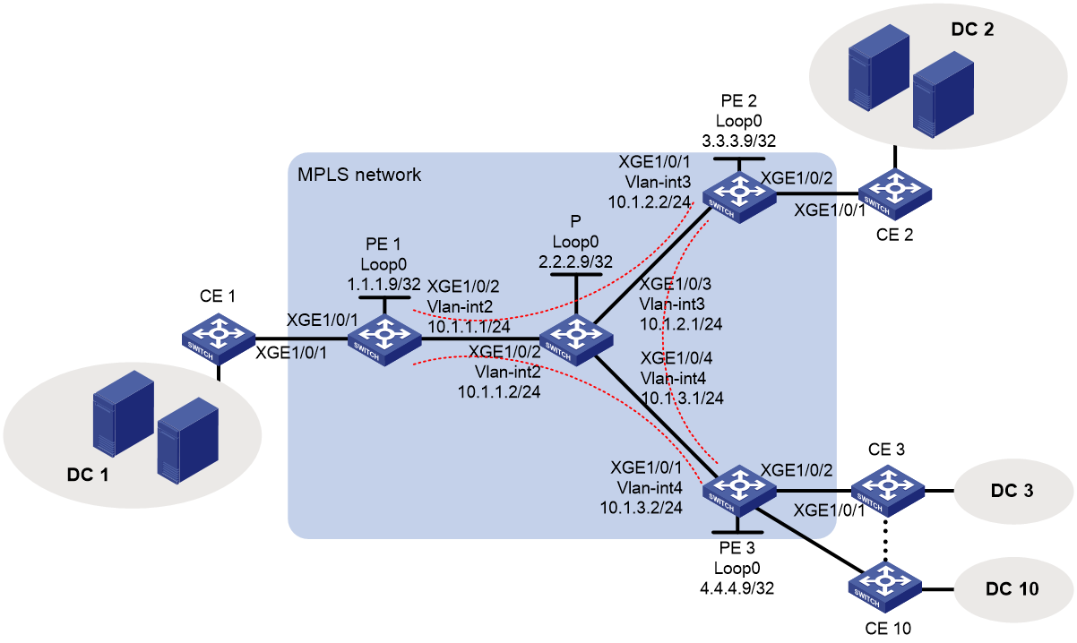
Analysis
· Deploy MPLS on the backbone network and use LSP as the public tunnel.
· Deploy BGP-based VPLS service on PEs and configure label blocks to meet expansion requirements.
· To achieve VLAN isolation between sites, create VSIs user_a and user_b and bind them to VLAN 100 and VLAN 200, respectively.
Applicable hardware and software versions
Table 3 Applicable hardware and software versions
|
Hardware |
Software version |
|
S6812 series S6813 series |
Release 6628Pxx series |
|
S6550XE-HI series |
Release 8106Pxx |
|
S6525XE-HI series |
Release 8106Pxx |
|
S5850 series |
Unsupported |
|
S5570S-EI series |
Unsupported |
|
S5560X-EI series |
Release 6628Pxx |
|
S5560X-HI series |
Release 6628Pxx |
|
S5500V2-EI series |
Release 6628Pxx series |
|
MS4520V2-30F |
Release 6628Pxx series |
|
MS4520V2-30C MS4520V2-54C |
Release 6628Pxx series |
|
MS4520V2-28S MS4520V2-24TP |
Unsupported |
|
S6520X-HI series S6520X-EI series |
Release 6628Pxx series |
|
S6520X-SI series S6520-SI series |
Release 6628Pxx series |
|
S5000-EI series |
Release 6628Pxx series |
|
MS4600 series |
Release 6628Pxx series |
|
ES5500 series |
Release 6628Pxx series |
|
S5560S-EI series S5560S-SI series |
Unsupported |
|
S5500V3-24P-SI S5500V3-48P-SI |
Unsupported |
|
S5500V3-SI series (excluding the S5500V3-24P-SI and S5500V3-48P-SI) |
Unsupported |
|
S5170-EI series |
Unsupported |
|
S5130S-HI series S5130S-EI series S5130S-SI series S5130S-LI series |
Unsupported |
|
S5120V2-SI series S5120V2-LI Series |
Unsupported |
|
S5120V3-EI series |
Unsupported |
|
S5120V3-36F-SI S5120V3-28P-HPWR-SI S5120V3-54P-PWR-SI |
Unsupported |
|
S5120V3-SI series (excluding S5120V3-36F-SI, S5120V3-28P-HPWR-SI, and S5120V3-54P-PWR-SI) |
Unsupported |
|
S5120V3-LI series |
Unsupported |
|
S3600V3-EI series |
Unsupported |
|
S3600V3-SI series |
Unsupported |
|
S3100V3-EI series S3100V3-SI series |
Unsupported |
|
S5110V2 series |
Unsupported |
|
S5110V2-SI series |
Unsupported |
|
S5000V3-EI series S5000V5-EI series |
Unsupported |
|
S5000E-X series S5000X-EI series |
Unsupported |
|
E128C E152C E500C series E500D series |
Unsupported |
|
MS4320V2 series MS4320V3 series MS4300V2 series MS4320 series MS4200 series |
Unsupported |
|
WS5850-WiNet series |
Unsupported |
|
WS5820-WiNet series WS5810-WiNet series |
Unsupported |
|
WAS6000 series |
Unsupported |
|
IE4300-12P-AC & IE4300-12P-PWR IE4300-M series IE4320 series |
Unsupported |
|
S5135S-EI series |
Unsupported |
Procedure
Configuring IGP on the MPLS backbone network to enable communication between PEs and P devices on the backbone network
· Configure PE 1:
# Configure a loopback interface address.
<PE1> system-view
[PE1] interface loopback 0
[PE1-LoopBack0] ip address 1.1.1.9 32
[PE1-LoopBack0] quit
# Create VLAN 2 and add Ten-GigabitEthernet 1/0/2 to VLAN 2.
[PE1] vlan 2
[PE1-vlan2] port ten-gigabitethernet 1/0/2
[PE1-vlan2] quit
# Create VLAN-interface 2.
[PE1] interface vlan-interface 2
[PE1-Vlan-interface2] ip address 10.1.1.1 24
[PE1-Vlan-interface2] quit
# Configure OSPF on PE 1 for establishing LSPs.
[PE1] ospf
[PE1-ospf-1] area 0
[PE1-ospf-1-area-0.0.0.0] network 10.1.1.0 0.0.0.255
[PE1-ospf-1-area-0.0.0.0] network 1.1.1.9 0.0.0.0
[PE1-ospf-1-area-0.0.0.0] quit
[PE1-ospf-1] quit
· Configure PE 2:
# Configure a loopback interface address.
<PE2> system-view
[PE2] interface loopback 0
[PE2-LoopBack0] ip address 3.3.3.9 32
[PE2-LoopBack0] quit
# Create VLAN 3 and add Ten-GigabitEthernet 1/0/1 to VLAN 3.
[PE2] vlan 3
[PE2-vlan3] port ten-gigabitethernet 1/0/1
[PE2-vlan3] quit
# Create VLAN-interface 3.
[PE2] interface vlan-interface 3
[PE2-Vlan-interface3] ip address 10.1.2.2 24
[PE2-Vlan-interface3] quit
# Configure OSPF on PE 2 for establishing LSPs.
[PE2] ospf
[PE2-ospf-1] area 0
[PE2-ospf-1-area-0.0.0.0] network 10.1.2.0 0.0.0.255
[PE2-ospf-1-area-0.0.0.0] network 3.3.3.9 0.0.0.0
[PE2-ospf-1-area-0.0.0.0] quit
[PE2-ospf-1] quit
· Configure PE 3:
# Configure a loopback interface address.
<PE3> system-view
[PE3] interface loopback 0
[PE3-LoopBack0] ip address 4.4.4.9 32
[PE3-LoopBack0] quit
# Create VLAN 4 and add Ten-GigabitEthernet 1/0/1 to VLAN 4.
[PE3] vlan 4
[PE3-vlan4] port ten-gigabitethernet 1/0/1
[PE3-vlan4] quit
# Create VLAN-interface 4.
[PE3] interface vlan-interface 4
[PE3-Vlan-interface4] ip address 10.1.3.2 24
[PE3-Vlan-interface4] quit
# Configure OSPF on PE 3 for establishing LSPs.
[PE3] ospf
[PE3-ospf-1] area 0
[PE3-ospf-1-area-0.0.0.0] network 10.1.3.0 0.0.0.255
[PE3-ospf-1-area-0.0.0.0] network 4.4.4.9 0.0.0.0
[PE3-ospf-1-area-0.0.0.0] quit
[PE3-ospf-1] quit
· Configure the P device:
# Configure a loopback interface address.
<P> system-view
[P] interface loopback 0
[P-LoopBack0] ip address 2.2.2.9 32
[P-LoopBack0] quit
# Create VLAN 2 and add Ten-GigabitEthernet 1/0/2 to VLAN 2.
[P] vlan 2
[P-vlan2] port ten-gigabitethernet 1/0/2
[P-vlan2] quit
# Configure VLAN-interface 2.
[P] interface vlan-interface 2
[P-Vlan-interface2] ip address 10.1.1.2 24
[P-Vlan-interface2] quit
# Create VLAN 3 and add Ten-GigabitEthernet 3/0/1 to VLAN 3.
[P] vlan 3
[P-vlan3] port ten-gigabitethernet 1/0/3
[P-vlan3] quit
# Configure VLAN-interface 3.
[P] interface vlan-interface 3
[P-Vlan-interface3] ip address 10.1.2.1 24
[P-Vlan-interface3] quit
# Create VLAN 4 and add Ten-GigabitEthernet 1/0/4 to VLAN 4.
[P] vlan 4
[P-vlan4] port ten-gigabitethernet 1/0/4
[P-vlan4] quit
# Configure VLAN-interface 4.
[P] interface vlan-interface 4
[P-Vlan-interface4] ip address 10.1.3.1 24
[P-Vlan-interface4] quit
# Configure OSPF on the P device for establishing LSPs.
[P] ospf
[P-ospf-1] area 0
[P-ospf-1-area-0.0.0.0] network 10.1.1.0 0.0.0.255
[P-ospf-1-area-0.0.0.0] network 10.1.2.0 0.0.0.255
[P-ospf-1-area-0.0.0.0] network 10.1.3.0 0.0.0.255
[P-ospf-1-area-0.0.0.0] network 2.2.2.9 0.0.0.0
[P-ospf-1-area-0.0.0.0] quit
[P-ospf-1] quit
Configuring basic MPLS and MPLS LDP on the MPLS backbone network to establish LDP LSPs
· Configure PE 1:
# Configure an LSR ID.
[PE1] mpls lsr-id 1.1.1.9
# Enable LDP globally.
[PE1] mpls ldp
[PE1-ldp] quit
# Enable MPLS and LDP VLAN-interface 2.
[PE1] interface vlan-interface 2
[PE1-Vlan-interface2] mpls enable
[PE1-Vlan-interface2] mpls ldp enable
[PE1-Vlan-interface2] quit
· Configure PE 2:
# Configure an LSR ID.
[PE2] mpls lsr-id 3.3.3.9
# Enable LDP globally.
[PE2] mpls ldp
[PE2-ldp] quit
# Enable MPLS and LDP on VLAN-interface 3.
[PE2] interface vlan-interface 3
[PE2-Vlan-interface3] mpls enable
[PE2-Vlan-interface3] mpls ldp enable
[PE2-Vlan-interface3] quit
· Configure PE 3:
# Configure an LSR ID.
[PE3] mpls lsr-id 4.4.4.9
# Enable LDP globally.
[PE3] mpls ldp
[PE3-ldp] quit
# Enable MPLS and LDP on VLAN-interface 4.
[PE3] interface vlan-interface 4
[PE3-Vlan-interface4] mpls enable
[PE3-Vlan-interface4] mpls ldp enable
[PE3-Vlan-interface4] quit
· Configure the P device:
# Configure an LSR ID.
[P] mpls lsr-id 2.2.2.9
# Enable LDP globally.
[P] mpls ldp
[P-ldp] quit
# Enable MPLS and LDP VLAN-interface 2.
[P] interface vlan-interface 2
[P-Vlan-interface2] mpls enable
[P-Vlan-interface2] mpls ldp enable
[P-Vlan-interface2] quit
# Enable MPLS and LDP on VLAN-interface 3.
[P] interface vlan-interface 3
[P-Vlan-interface3] mpls enable
[P-Vlan-interface3] mpls ldp enable
[P-Vlan-interface3] quit
# Enable MPLS and LDP on VLAN-interface 4.
[P] interface vlan-interface 4
[P-Vlan-interface4] mpls enable
[P-Vlan-interface4] mpls ldp enable
[P-Vlan-interface4] quit
Creating a VSI and configuring BGP PWs
· Configure PE 1:
# Create an IBGP connection to PE 2 and PE 3, respectively.
[PE1] bgp 100
[PE1-bgp-default] peer 3.3.3.9 as-number 100
[PE1-bgp-default] peer 3.3.3.9 connect-interface loopback 0
[PE1-bgp-default] peer 4.4.4.9 as-number 100
[PE1-bgp-default] peer 4.4.4.9 connect-interface loopback 0
# Enable BGP to advertise L2VPN information.
[PE1-bgp-default] address-family l2vpn
[PE1-bgp-default-l2vpn] peer 3.3.3.9 enable
[PE1-bgp-default-l2vpn] peer 4.4.4.9 enable
[PE1-bgp-default-l2vpn] quit
[PE1-bgp-default] quit
# Enable MPLS L2VPN globally.
[PE1] l2vpn enable
# Create VSI user_a that automatically discovers neighbors through BGP.
[PE1] vsi user_a
[PE1-vsi-user_a] auto-discovery bgp
# Configure an RD and route target for the auto-discovery VSI.
[PE1-vsi-user_a-auto] route-distinguisher 100:1
[PE1-vsi-user_a-auto] vpn-target 111:1
# Use BGP to create a PW to an automatically discovered remote PE.
[PE1-vsi-user_a-auto] signaling-protocol bgp
# Configure the site number for PE 1 in this instance (using 1 as an example), and the number of PEs that can establish connections in this instance (the value should be 25, because there are 10 sites in the network and 15 more will be added).
[PE1-vsi-user_a-auto-bgp] site 1 range 25
[PE1-vsi-user_a-auto-bgp] quit
[PE1-vsi-user_a-auto] quit
[PE1-vsi-user_a] quit
# Create VSI user_b that automatically discovers neighbors through BGP.
[PE1] vsi user_b
[PE1-vsi-user_b] auto-discovery bgp
# Configure an RD and route target for the auto-discovery VSI.
[PE1-vsi-user_b-auto] route-distinguisher 200:1
[PE1-vsi-user_b-auto] vpn-target 222:1
# Use BGP to create a PW to an automatically discovered remote PE.
[PE1-vsi-user_b-auto] signaling-protocol bgp
# Configure the site number for PE 1 in this instance (using 1 as an example), and the number of PEs that can establish connections in this instance (the value should be 25, because there are 10 sites in the network and 15 more will be added).
[PE1-vsi-user_b-auto-bgp] site 1 range 25
[PE1-vsi-user_b-auto-bgp] quit
[PE1-vsi-user_b-auto] quit
[PE1-vsi-user_b] quit
· Configure PE 2:
# Create an IBGP connection to PE 1 and PE 3, respectively.
[PE2] bgp 100
[PE2-bgp-default] peer 1.1.1.9 as-number 100
[PE2-bgp-default] peer 1.1.1.9 connect-interface loopback 0
[PE2-bgp-default] peer 4.4.4.9 as-number 100
[PE2-bgp-default] peer 4.4.4.9 connect-interface loopback 0
# Enable BGP to advertise L2VPN information.
[PE2-bgp-default] address-family l2vpn
[PE2-bgp-default-l2vpn] peer 1.1.1.9 enable
[PE2-bgp-default-l2vpn] peer 4.4.4.9 enable
[PE2-bgp-default-l2vpn] quit
[PE2-bgp-default] quit
# Enable MPLS L2VPN globally.
[PE2] l2vpn enable
# Create VSI user_a that automatically discovers neighbors through BGP.
[PE2] vsi user_a
[PE2-vsi-user_a] auto-discovery bgp
# Configure an RD and route target for the auto-discovery VSI.
[PE2-vsi-user_a-auto] route-distinguisher 100:1
[PE2-vsi-user_a-auto] vpn-target 111:1
# Use BGP to create a PW to an automatically discovered remote PE.
[PE2-vsi-user_a-auto] signaling-protocol bgp
# Configure the site number for PE 2 in this instance (using 2 as an example), and the number of PEs that can establish connections in this instance (the value should be 25, because there are 10 sites in the network and 15 more will be added).
[PE2-vsi-user_a-auto-bgp] site 2 range 25
[PE2-vsi-user_a-auto-bgp] quit
[PE2-vsi-user_a-auto] quit
[PE2-vsi-user_a] quit
# Create VSI user_b that automatically discovers neighbors through BGP.
[PE2] vsi user_b
[PE2-vsi-user_b] auto-discovery bgp
# Configure an RD and route target for the auto-discovery VSI.
[PE2-vsi-user_b-auto] route-distinguisher 200:1
[PE2-vsi-user_b-auto] vpn-target 222:1
# Use BGP to create a PW to an automatically discovered remote PE.
[PE2-vsi-user_b-auto] signaling-protocol bgp
# Configure the site number for PE 2 in this instance (using 2 as an example), and the number of PEs that can establish connections in this instance (the value should be 25, because there are 10 sites in the network and 15 more will be added).
[PE2-vsi-user_b-auto-bgp] site 2 range 25
[PE2-vsi-user_b-auto-bgp] quit
[PE2-vsi-user_b-auto] quit
[PE2-vsi-user_b] quit
· Configure PE 3:
# Create an IBGP connection to PE 1 and PE 2, respectively.
[PE3] bgp 100
[PE3-bgp-default] peer 1.1.1.9 as-number 100
[PE3-bgp-default] peer 1.1.1.9 connect-interface loopback 0
[PE3-bgp-default] peer 3.3.3.9 as-number 100
[PE3-bgp-default] peer 3.3.3.9 connect-interface loopback 0
# Enable BGP to advertise L2VPN information.
[PE3-bgp-default] address-family l2vpn
[PE3-bgp-default-l2vpn] peer 1.1.1.9 enable
[PE3-bgp-default-l2vpn] peer 3.3.3.9 enable
[PE3-bgp-default-l2vpn] quit
[PE3-bgp-default] quit
# Enable MPLS L2VPN globally.
[PE3] l2vpn enable
# Create VSI user_a that automatically discovers neighbors through BGP.
[PE3] vsi user_a
[PE3-vsi-user_a] auto-discovery bgp
# Configure an RD and route target for the auto-discovery VSI.
[PE3-vsi-user_a-auto] route-distinguisher 100:1
[PE3-vsi-user_a-auto] vpn-target 111:1
# Use BGP to create a PW to an automatically discovered remote PE.
[PE3-vsi-user_a-auto] signaling-protocol bgp
# Configure the site number for PE 3 in this instance (using 3 as an example), and the number of PEs that can establish connections in this instance (the value should be 25, because there are 10 sites in the network and 15 more will be added).
[PE3-vsi-user_a-auto-bgp] site 3 range 25
[PE3-vsi-user_a-auto-bgp] quit
[PE3-vsi-user_a-auto] quit
[PE3-vsi-user_a] quit
# Create VSI user_b that automatically discovers neighbors through BGP.
[PE3] vsi user_b
[PE3-vsi-user_b] auto-discovery bgp
# Configure an RD and route target for the auto-discovery VSI.
[PE3-vsi-user_b-auto] route-distinguisher 200:1
[PE3-vsi-user_b-auto] vpn-target 222:1
# Use BGP to create a PW to an automatically discovered remote PE.
[PE3-vsi-user_b-auto] signaling-protocol bgp
# Configure the site number for PE 3 in this instance (using 3 as an example), and the number of PEs that can establish connections in this instance (the value should be 25, because there are 10 sites in the network and 15 more will be added).
[PE3-vsi-user_b-auto-bgp] site 3 range 25
[PE3-vsi-user_b-auto-bgp] quit
[PE3-vsi-user_b-auto] quit
[PE3-vsi-user_b] quit
Configuring service instances for data from different VLANs and bind them to different VSIs
· Configure PE 1:
# Create service instance 100 on Ten-GigabitEthernet 1/0/1 to match packets from VLAN 100, and bind it to VSI instance user_a.
[PE1] interface ten-gigabitethernet 1/0/1
[PE1-Ten-GigabitEthernet1/0/1] service-instance 100
[PE1-Ten-GigabitEthernet1/0/1-srv100] encapsulation s-vid 100
[PE1-Ten-GigabitEthernet1/0/1-srv100] xconnect vsi user_a
[PE1-Ten-GigabitEthernet1/0/1-srv100] quit
# Create service instance 200 on Ten-GigabitEthernet 1/0/1 to match packets from VLAN 200, and bind it to VSI instance user_b.
[PE1-Ten-GigabitEthernet1/0/1] service-instance 200
[PE1-Ten-GigabitEthernet1/0/1-srv200] encapsulation s-vid 200
[PE1-Ten-GigabitEthernet1/0/1-srv200] xconnect vsi user_b
[PE1-Ten-GigabitEthernet1/0/1-srv200] quit
[PE1-Ten-GigabitEthernet1/0/1] quit
· Configure PE 2:
# Create service instance 100 on Ten-GigabitEthernet 1/0/2 to match packets from VLAN 100, and bind it to VSI instance user_a.
[PE2] interface ten-gigabitethernet 1/0/2
[PE2-Ten-GigabitEthernet1/0/2] service-instance 100
[PE2-Ten-GigabitEthernet1/0/2-srv100] encapsulation s-vid 100
[PE2-Ten-GigabitEthernet1/0/2-srv100] xconnect vsi user_a
[PE2-Ten-GigabitEthernet1/0/2-srv100] quit
# Create service instance 200 on Ten-GigabitEthernet 1/0/2 to match packets from VLAN 200, and bind it to VSI instance user_b.
[PE2-Ten-GigabitEthernet1/0/2] service-instance 200
[PE2-Ten-GigabitEthernet1/0/2-srv200] encapsulation s-vid 200
[PE2-Ten-GigabitEthernet1/0/2-srv200] xconnect vsi user_b
[PE2-Ten-GigabitEthernet1/0/2-srv200] quit
[PE2-Ten-GigabitEthernet1/0/2] quit
· Configure PE 3:
# Create service instance 100 on Ten-GigabitEthernet 1/0/2 to match packets from VLAN 100, and bind it to VSI user_a.
[PE3] interface ten-gigabitethernet 1/0/2
[PE3-Ten-GigabitEthernet1/0/2] service-instance 100
[PE3-Ten-GigabitEthernet1/0/2-srv100] encapsulation s-vid 100
[PE3-Ten-GigabitEthernet1/0/2-srv100] xconnect vsi user_a
[PE3-Ten-GigabitEthernet1/0/2-srv100] quit
# Create service instance 200 on Ten-GigabitEthernet 1/0/2 to match packets from VLAN 200, and bind it to VSI instance user_b.
[PE3-Ten-GigabitEthernet1/0/2] service-instance 200
[PE3-Ten-GigabitEthernet1/0/2-srv200] encapsulation s-vid 200
[PE3-Ten-GigabitEthernet1/0/2-srv200] xconnect vsi user_b
[PE3-Ten-GigabitEthernet1/0/2-srv200] quit
[PE3-Ten-GigabitEthernet1/0/2] quit
# Configure interfaces on other CEs in the same way Ten-GigabitEthernet1/0/2 is configured.
Connecting CEs to PEs
# Configure the uplink interface to the PE to allow tagged packets from the site to pass through. The following uses CE 1 as an example. Configure other CEs in the same way CE1 is configured.
<CE1> system-view
[CE1] vlan 100
[CE1-vlan100] quit
[CE1] vlan 200
[CE1-vlan200] quit
[CE1] interface ten-gigabitethernet 1/0/1
[CE1-Ten-GigabitEthernet1/0/1] port link-type trunk
[CE1-Ten-GigabitEthernet1/0/1] port trunk permit vlan 100 200
Verifying the configuration
Verifying the public network LSPs
# Execute the display mpls ldp lsp command to verify that the LSPs have been established.
[PE1] display mpls ldp lsp
Status Flags: * - stale, L - liberal
Statistics:
FECs: 4 Ingress LSPs: 3 Transit LSPs: 3 Egress LSPs: 1
FEC In/Out Label Nexthop OutInterface
1.1.1.9/32 3/-
-/1151(L)
2.2.2.9/32 -/3 10.1.1.2 Vlan2
1151/3 10.1.1.2 Vlan2
3.3.3.9/32 -/1150 10.1.1.2 Vlan2
1150/1150 10.1.1.2 Vlan2
4.4.4.9/32 -/1149 10.1.1.2 Vlan2
1149/1149 10.1.1.2 Vlan2
Verifying PW status
# Execute the display l2vpn pw command on each PE. The output shows that a PW has been established and in up state.
[PE1] display l2vpn pw
Flags: M - main, B - backup, H - hub link, S - spoke link, N - no split horizon
Total number of PWs: 2, 2 up, 0 blocked, 0 down, 0 defect
VSI Name: user_a
Peer PW ID/Rmt Site In/Out Label Proto Flag Link ID State
3.3.3.9 2 131074/131073 BGP M 257 Up
4.4.4.9 3 131075/131073 BGP M 258 Up
VSI Name: user_b
Peer PW ID/Rmt Site In/Out Label Proto Flag Link ID State
3.3.3.9 2 131071/131070 BGP M 257 Up
4.4.4.9 3 131072/131070 BGP M 258 Up
# Use ping to identify whether hosts within the same VLAN but at different sites can reach each other. If the ping operation succeeds, the VPLS is created successfully.
Configuration files
· PE 1
#
ospf 1
area 0.0.0.0
network 1.1.1.9 0.0.0.0
network 10.1.1.0 0.0.0.255
#
mpls lsr-id 1.1.1.9
#
vlan 2
#
mpls ldp
#
l2vpn enable
#
vsi user_a
auto-discovery bgp
route-distinguisher 100:1
vpn-target 111:1 export-extcommunity
vpn-target 111:1 import-extcommunity
signaling-protocol bgp
site 1 range 25 default-offset 0
#
vsi user_b
auto-discovery bgp
route-distinguisher 200:1
vpn-target 222:1 export-extcommunity
vpn-target 222:1 import-extcommunity
signaling-protocol bgp
site 1 range 25 default-offset 0
#
interface LoopBack0
ip address 1.1.1.9 255.255.255.255
#
interface Vlan-interface2
ip address 10.1.1.1 255.255.255.0
mpls enable
mpls ldp enable
#
interface Ten-GigabitEthernet1/0/1
port link-mode bridge
service-instance 100
encapsulation s-vid 100
xconnect vsi user_a
service-instance 200
encapsulation s-vid 200
xconnect vsi user_b
#
interface Ten-GigabitEthernet1/0/2
port link-mode bridge
port access vlan 2
#
bgp 100
peer 3.3.3.9 as-number 100
peer 3.3.3.9 connect-interface LoopBack0
peer 4.4.4.9 as-number 100
peer 4.4.4.9 connect-interface LoopBack0
#
address-family l2vpn
peer 3.3.3.9 enable
peer 4.4.4.9 enable
#
· PE 2
#
ospf 1
area 0.0.0.0
network 10.1.2.0 0.0.0.255
network 3.3.3.9 0.0.0.0
#
mpls lsr-id 3.3.3.9
#
vlan 3
#
mpls ldp
#
l2vpn enable
#
vsi user_a
auto-discovery bgp
route-distinguisher 100:1
vpn-target 111:1 export-extcommunity
vpn-target 111:1 import-extcommunity
signaling-protocol bgp
site 2 range 25 default-offset 0
#
vsi user_b
auto-discovery bgp
route-distinguisher 200:1
vpn-target 222:1 export-extcommunity
vpn-target 222:1 import-extcommunity
signaling-protocol bgp
site 2 range 25 default-offset 0
#
interface LoopBack0
ip address 3.3.3.9 255.255.255.255
#
interface Vlan-interface3
ip address 10.1.2.2 255.255.255.0
mpls enable
mpls ldp enable
#
interface Ten-GigabitEthernet1/0/1
port link-mode bridge
port access vlan 3
#
interface Ten-GigabitEthernet1/0/2
port link-mode bridge
service-instance 100
encapsulation s-vid 100
xconnect vsi user_a
service-instance 200
encapsulation s-vid 200
xconnect vsi user_b
#
bgp 100
peer 1.1.1.9 as-number 100
peer 1.1.1.9 connect-interface LoopBack0
peer 4.4.4.9 as-number 100
peer 4.4.4.9 connect-interface LoopBack0
#
address-family l2vpn
peer 1.1.1.9 enable
peer 4.4.4.9 enable
#
· PE 3
#
ospf 1
area 0.0.0.0
network 10.1.3.0 0.0.0.255
network 4.4.4.9 0.0.0.0
#
mpls lsr-id 4.4.4.9
#
vlan 4
#
mpls ldp
#
l2vpn enable
#
vsi user_a
auto-discovery bgp
route-distinguisher 100:1
vpn-target 111:1 export-extcommunity
vpn-target 111:1 import-extcommunity
signaling-protocol bgp
site 3 range 25 default-offset 0
#
vsi user_b
auto-discovery bgp
route-distinguisher 200:1
vpn-target 222:1 export-extcommunity
vpn-target 222:1 import-extcommunity
signaling-protocol bgp
site 3 range 25 default-offset 0
#
interface LoopBack0
ip address 4.4.4.9 255.255.255.255
#
interface Vlan-interface4
ip address 10.1.3.2 255.255.255.0
mpls enable
mpls ldp enable
#
interface Ten-GigabitEthernet1/0/1
port link-mode bridge
port access vlan 4
#
interface Ten-GigabitEthernet1/0/2
port link-mode bridge
service-instance 100
encapsulation s-vid 100
xconnect vsi user_a
service-instance 200
encapsulation s-vid 200
xconnect vsi user_b
#
bgp 100
peer 1.1.1.9 as-number 100
peer 1.1.1.9 connect-interface LoopBack0
peer 3.3.3.9 as-number 100
peer 3.3.3.9 connect-interface LoopBack0
#
address-family l2vpn
peer 1.1.1.9 enable
peer 3.3.3.9 enable
#
· P
#
ospf 1
area 0.0.0.0
network 10.1.1.0 0.0.0.255
network 10.1.2.0 0.0.0.255
network 10.1.3.0 0.0.0.255
network 2.2.2.9 0.0.0.0
#
mpls lsr-id 2.2.2.9
#
vlan 2 to 4
#
mpls ldp
#
interface LoopBack0
ip address 2.2.2.9 255.255.255.255
#
interface Vlan-interface2
ip address 10.1.1.2 255.255.255.0
mpls enable
mpls ldp enable
#
interface Vlan-interface3
ip address 10.1.2.1 255.255.255.0
mpls enable
mpls ldp enable
#
interface Vlan-interface4
ip address 10.1.3.1 255.255.255.0
mpls enable
mpls ldp enable
#
interface Ten-GigabitEthernet1/0/2
port link-mode bridge
port access vlan 2
#
interface Ten-GigabitEthernet1/0/3
port link-mode bridge
port access vlan 3
#
interface Ten-GigabitEthernet1/0/4
port link-mode bridge
port access vlan 4
#
· CE 1 through CE 10
#
vlan 100
#
vlan 200
#
interface Ten-GigabitEthernet1/0/1
port link-mode bridge
port link-type trunk
port trunk permit vlan 100 200
#
Example: Configuring H-VPLS (LSP access)
Network configuration
A provider provides VPLS service, with numerous users in various locations. To simplify the network structure and reduce device load and maintenance workload, deploy H-VPLS on the network.
As shown in Figure 4, make sure the following requirements are met:
· Branches at different locations connect to the carrier MPLS network through UPEs that support MPLS L2VPN.
· NPEs connect to the UPEs by using the LSP access mode.
· The UPEs are dual homed to two NPEs for increased reliability.

|
Device |
Interface |
IP address |
Device |
Interface |
IP address |
|
UPE 1 |
Loop0 |
11.1.1.1/32 |
UPE 2 |
Loop0 |
14.1.1.1/32 |
|
|
Vlan-int10 |
11.1.2.1/24 |
|
Vlan-int12 |
20.1.1.1/24 |
|
|
Vlan-int11 |
11.1.3.1/24 |
|
Vlan-int13 |
20.1.2.1/24 |
|
NPE 1 |
Loop0 |
1.1.1.1/32 |
NPE 3 |
Loop0 |
3.3.3.3/32 |
|
|
Vlan-int10 |
11.1.2.2/24 |
|
Vlan-int13 |
20.1.2.2/24 |
|
NPE 2 |
Loop0 |
2.2.2.2/32 |
NPE 4 |
Loop0 |
4.4.4.4/32 |
|
|
Vlan-int11 |
11.1.3.2/24 |
|
Vlan-int12 |
20.1.1.2/24 |
Analysis
· On the UPEs, set up primary/backup peers to determine the primary and backup status of the links.
· Configure a service instance and corresponding match rules on the downlink port of each UPE identify packets from the customer network that require a VPLS tunnel for transmission.
· To achieve VLAN isolation between sites, create VSIs user_a and user_b and bind them to VLAN 100 and VLAN 200, respectively.
Applicable hardware and software versions
Table 4 Applicable hardware and software versions
|
Hardware |
Software version |
|
S6812 series S6813 series |
Release 6628Pxx series |
|
S6550XE-HI series |
Release 8106Pxx |
|
S6525XE-HI series |
Release 8106Pxx |
|
S5850 series |
Unsupported |
|
S5570S-EI series |
Unsupported |
|
S5560X-EI series |
Release 6628Pxx |
|
S5560X-HI series |
Release 6628Pxx |
|
S5500V2-EI series |
Release 6628Pxx series |
|
MS4520V2-30F |
Release 6628Pxx series |
|
MS4520V2-30C MS4520V2-54C |
Release 6628Pxx series |
|
MS4520V2-28S MS4520V2-24TP |
Unsupported |
|
S6520X-HI series S6520X-EI series |
Release 6628Pxx series |
|
S6520X-SI series S6520-SI series |
Release 6628Pxx series |
|
S5000-EI series |
Release 6628Pxx series |
|
MS4600 series |
Release 6628Pxx series |
|
ES5500 series |
Release 6628Pxx series |
|
S5560S-EI series S5560S-SI series |
Unsupported |
|
S5500V3-24P-SI S5500V3-48P-SI |
Unsupported |
|
S5500V3-SI series (excluding the S5500V3-24P-SI and S5500V3-48P-SI) |
Unsupported |
|
S5170-EI series |
Unsupported |
|
S5130S-HI series S5130S-EI series S5130S-SI series S5130S-LI series |
Unsupported |
|
S5120V2-SI series S5120V2-LI Series |
Unsupported |
|
S5120V3-EI series |
Unsupported |
|
S5120V3-36F-SI S5120V3-28P-HPWR-SI S5120V3-54P-PWR-SI |
Unsupported |
|
S5120V3-SI series (excluding S5120V3-36F-SI, S5120V3-28P-HPWR-SI, and S5120V3-54P-PWR-SI) |
Unsupported |
|
S5120V3-LI series |
Unsupported |
|
S3600V3-EI series |
Unsupported |
|
S3600V3-SI series |
Unsupported |
|
S3100V3-EI series S3100V3-SI series |
Unsupported |
|
S5110V2 series |
Unsupported |
|
S5110V2-SI series |
Unsupported |
|
S5000V3-EI series S5000V5-EI series |
Unsupported |
|
S5000E-X series S5000X-EI series |
Unsupported |
|
E128C E152C E500C series E500D series |
Unsupported |
|
MS4320V2 series MS4320V3 series MS4300V2 series MS4320 series MS4200 series |
Unsupported |
|
WS5850-WiNet series |
Unsupported |
|
WS5820-WiNet series WS5810-WiNet series |
Unsupported |
|
WAS6000 series |
Unsupported |
|
IE4300-12P-AC & IE4300-12P-PWR IE4300-M series IE4320 series |
Unsupported |
|
S5135S-EI series |
Unsupported |
Procedure
Configuring basic network settings
1. Create interfaces for UPE and NPE devices as shown in Figure 4 and configure IP addresses for them. (Details not shown.)
2. Configure IGP on the MPLS backbone network to ensure that all interfaces on the NPEs and UPEs are reachable to each other. (Details not shown.)
3. Configure basic MPLS and MPLS LDP on the backbone network to establish LDP LSPs. (Details not shown.)
4. Configure interfaces on each CE that connect to UPEs as a trunk port and permit packets from VLAN 100 and VLAN 200 to pass through with tags. (Details not shown.)
Configuring UPE 1
# Configure basic MPLS.
<UPE1> system-view
[UPE1] mpls lsr-id 11.1.1.1
[UPE1] mpls ldp
[UPE1-ldp] quit
# Configure basic MPLS capability on the interface connected with NPE 1.
[UPE1] interface vlan-interface 10
[UPE1-Vlan-interface10] mpls enable
[UPE1-Vlan-interface10] mpls ldp enable
[UPE1-Vlan-interface10] quit
# Configure basic MPLS capability on the interface connected with NPE 2.
[UPE1] interface vlan-interface 11
[UPE1-Vlan-interface11] mpls enable
[UPE1-Vlan-interface11] mpls ldp enable
[UPE1-Vlan-interface11] quit
# Enable MPLS L2VPN.
[UPE1] l2vpn enable
# Configure VSI user_a that uses LDP as the PW signaling protocol.
[UPE1] vsi user_a
[UPE1-vsi-user_a] pwsignaling ldp
# Specify the switchover mode and set the wait time to 120 seconds for the switchover.
[UPE1-vsi-user_a-ldp] revertive wtr 120
# Configure a static PW between UPE 1 and NPE 1, and a backup static PW between UPE 1 and NPE 2.
[UPE1-vsi-user_a-ldp] peer 1.1.1.1 pw-id 500
[UPE1-vsi-user_a-ldp-1.1.1.1-500] backup-peer 2.2.2.2 pw-id 500
[UPE1-vsi-user_a-ldp-1.1.1.1-500-backup] quit
[UPE1-vsi-user_a-ldp-1.1.1.1-500] quit
[UPE1-vsi-user_a-ldp] quit
[UPE1-vsi-user_a] quit
# Configure VSI user_b that uses LDP as the PW signaling protocol.
[UPE1] vsi user_b
[UPE1-vsi-user_b] pwsignaling ldp
# Specify the switchover mode and set the wait time to 120 seconds for the switchover.
[UPE1-vsi-user_b-ldp] revertive wtr 120
# Configure a static PW between UPE 1 and NPE 1, and a backup static PW between UPE 1 and NPE 2.
[UPE1-vsi-user_b-ldp] peer 1.1.1.1 pw-id 600
[UPE1-vsi-user_b-ldp-1.1.1.1-600] backup-peer 2.2.2.2 pw-id 600
[UPE1-vsi-user_b-ldp-1.1.1.1-600-backup] quit
[UPE1-vsi-user_b-ldp-1.1.1.1-600] quit
[UPE1-vsi-user_b-ldp] quit
[UPE1-vsi-user_b] quit
# Create service instance 1000 on Ten-GigabitEthernet 1/0/1 connected to Site A to match packets from VLAN 100, and bind it to VSI user_a.
[UPE1] interface ten-gigabitethernet 1/0/1
[UPE1-Ten-GigabitEthernet1/0/1] service-instance 1000
[UPE1-Ten-GigabitEthernet1/0/1-srv1000] encapsulation s-vid 100
[UPE1-Ten-GigabitEthernet1/0/1-srv1000] xconnect vsi user_a
[UPE1-Ten-GigabitEthernet1/0/1-srv1000] quit
# Create service instance 2000 on Ten-GigabitEthernet 1/0/1 to match packets from VLAN 200, and bind it to VSI user_b.
[UPE1-Ten-GigabitEthernet1/0/1] service-instance 2000
[UPE1-Ten-GigabitEthernet1/0/1-srv2000] encapsulation s-vid 200
[UPE1-Ten-GigabitEthernet1/0/1-srv2000] xconnect vsi user_b
[UPE1-Ten-GigabitEthernet1/0/1-srv2000] quit
# Create two service instances on Ten-GigabitEthernet1/0/2 connected to Site B to match packets from VALN 100 and VLAN 200, respectively, and bind VLAN 100 to VSI user_a and VLAN 200 to VSI user_b.
[UPE1] interface ten-gigabitethernet 1/0/2
[UPE1-Ten-GigabitEthernet1/0/2] service-instance 1000
[UPE1-Ten-GigabitEthernet1/0/2-srv1000] encapsulation s-vid 100
[UPE1-Ten-GigabitEthernet1/0/2-srv1000] xconnect vsi user_a
[UPE1-Ten-GigabitEthernet1/0/2-srv1000] quit
[UPE1-Ten-GigabitEthernet1/0/2] service-instance 2000
[UPE1-Ten-GigabitEthernet1/0/2-srv2000] encapsulation s-vid 200
[UPE1-Ten-GigabitEthernet1/0/2-srv2000] xconnect vsi user_b
[UPE1-Ten-GigabitEthernet1/0/2-srv2000] quit
Configuring NPE 1
# Configure basic MPLS capability on the interface connected with UPE 1.
<NPE1> system-view
[NPE1] interface vlan-interface 10
[NPE1-Vlan-interface10] mpls enable
[NPE1-Vlan-interface10] mpls ldp enable
[NPE1-Vlan-interface10] quit
# Enable MPLS L2VPN.
[NPE1] l2vpn enable
# Configure VSI user_a that uses LDP as the PW signaling protocol.
[NPE1] vsi user_a
[NPE1-vsi-user_a] pwsignaling ldp
# Specify UPE 1 as the peer.
[NPE1-vsi-user_a-ldp] peer 11.1.1.1 pw-id 500 no-split-horizon
[NPE1-vsi-user_a-ldp-11.1.1.1-500] quit
# Specify NPE 2, NPE 3, and NPE 4 as the peer NPEs.
[NPE1-vsi-user_a-ldp] peer 2.2.2.2 pw-id 500
[NPE1-vsi-user_a-ldp-2.2.2.2-500] quit
[NPE1-vsi-user_a-ldp] peer 3.3.3.3 pw-id 500
[NPE1-vsi-user_a-ldp-3.3.3.3-500] quit
[NPE1-vsi-user_a-ldp] peer 4.4.4.4 pw-id 500
[NPE1-vsi-user_a-ldp-4.4.4.4-500] quit
[NPE1-vsi-user_a-ldp] quit
[NPE1-vsi-user_a] quit
# Configure VSI user_b that uses LDP as the PW signaling protocol.
[NPE1] vsi user_b
[NPE1-vsi-user_b] pwsignaling ldp
# Specify UPE 1 as the peer.
[NPE1-vsi-user_b-ldp] peer 11.1.1.1 pw-id 600 no-split-horizon
[NPE1-vsi-user_b-ldp-11.1.1.1-500] quit
# Specify NPE 2, NPE 3, and NPE 4 as the peer NPEs.
[NPE1-vsi-user_b-ldp] peer 2.2.2.2 pw-id 600
[NPE1-vsi-user_b-ldp-2.2.2.2-600] quit
[NPE1-vsi-user_b-ldp] peer 3.3.3.3 pw-id 600
[NPE1-vsi-user_b-ldp-3.3.3.3-600] quit
[NPE1-vsi-user_b-ldp] peer 4.4.4.4 pw-id 600
[NPE1-vsi-user_b-ldp-4.4.4.4-600] quit
[NPE1-vsi-user_b-ldp] quit
[NPE1-vsi-user_b] quit
Configuring NPE 2
The configuration for NPE 2 is similar to that for NPE 1 except that VLAN interfaces connected to UPE and the NPE peers for them are different. For more information about the configuration, see the configuration file.
Configuring UPE 2
# Configure basic MPLS.
<UPE2> system-view
[UPE2] mpls lsr-id 14.1.1.1
[UPE2] mpls ldp
[UPE2-ldp] quit
# Configure basic MPLS capability on the interface connected with NPE 3.
[UPE2] interface vlan-interface 13
[UPE2-Vlan-interface13] mpls enable
[UPE2-Vlan-interface13] mpls ldp enable
[UPE2-Vlan-interface13] quit
# Configure basic MPLS capability on the interface connected with NPE 4.
[UPE2] interface vlan-interface 12
[UPE2-Vlan-interface12] mpls enable
[UPE2-Vlan-interface12] mpls ldp enable
[UPE2-Vlan-interface12] quit
# Enable MPLS L2VPN.
[UPE2] l2vpn enable
# Configure VSI user_a that uses LDP as the PW signaling protocol.
[UPE2] vsi user_a
[UPE2-vsi-user_a] pwsignaling ldp
# Specify the switchover mode and set the wait time to 120 seconds for the switchover.
[UPE2-vsi-user_a-ldp] revertive wtr 120
# Configure a static PW between UPE 2 and NPE 3, and a backup static PW between UPE 2 and NPE 4.
[UPE2-vsi-user_a-ldp] peer 3.3.3.3 pw-id 500
[UPE2-vsi-user_a-ldp-3.3.3.3-500] backup-peer 4.4.4.4 pw-id 500
[UPE2-vsi-user_a-ldp-3.3.3.3-500-backup] quit
[UPE2-vsi-user_a-ldp-3.3.3.3-500] quit
[UPE2-vsi-user_a-ldp] quit
[UPE2-vsi-user_a] quit
# Configure VSI user_b that uses LDP as the PW signaling protocol.
[UPE2] vsi user_b
[UPE2-vsi-user_b] pwsignaling ldp
# Specify the switchover mode and set the wait time to 120 seconds for the switchover.
[UPE2-vsi-user_b-ldp] revertive wtr 120
# Configure a static PW between UPE 2 and NPE 3, and a backup static PW between UPE 2 and NPE 4.
[UPE2-vsi-user_b-ldp] peer 3.3.3.3 pw-id 600
[UPE2-vsi-user_b-ldp-3.3.3.3-600] backup-peer 4.4.4.4 pw-id 600
[UPE2-vsi-user_b-ldp-3.3.3.3-600-backup] quit
[UPE2-vsi-user_b-ldp-3.3.3.3-600] quit
[UPE2-vsi-user_b-ldp] quit
[UPE2-vsi-user_b] quit
# Create service instance 1000 on Ten-GigabitEthernet 1/0/1 connected to Site E to match packets from VLAN 100, and bind it to VSI user_a.
[UPE2] interface ten-gigabitethernet 1/0/1
[UPE2-Ten-GigabitEthernet1/0/1] service-instance 1000
[UPE2-Ten-GigabitEthernet1/0/1-srv1000] encapsulation s-vid 100
[UPE2-Ten-GigabitEthernet1/0/1-srv1000] xconnect vsi user_a
[UPE2-Ten-GigabitEthernet1/0/1-srv1000] quit
# Create service instance 2000 on Ten-GigabitEthernet 1/0/1 to match packets from VLAN 200, and bind it to VSI user_b.
[UPE2-Ten-GigabitEthernet1/0/1] service-instance 2000
[UPE2-Ten-GigabitEthernet1/0/1-srv2000] encapsulation s-vid 200
[UPE2-Ten-GigabitEthernet1/0/1-srv2000] xconnect vsi user_b
[UPE2-Ten-GigabitEthernet1/0/1-srv2000] quit
Configuring NPE 3
# Configure basic MPLS capability on the interface connected with UPE 2.
[NPE3] interface vlan-interface 13
[NPE3-Vlan-interface13] mpls enable
[NPE3-Vlan-interface13] mpls ldp enable
[NPE3-Vlan-interface13] quit
# Configure MPLS L2VPN.
[NPE3] l2vpn enable
# Configure VSI user_a that uses LDP as the PW signaling protocol.
[NPE3] vsi user_a
[NPE3-vsi-user_a] pwsignaling ldp
# Specify UPE 2 as the peer.
[NPE3-vsi-user_a-ldp] peer 14.1.1.1 pw-id 500 no-split-horizon
[NPE3-vsi-user_a-ldp-14.1.1.1-500] quit
# Specify NPE 1, NPE 2, and NPE 4 as the peer NPEs.
[NPE3-vsi-user_a-ldp] peer 1.1.1.1 pw-id 500
[NPE3-vsi-user_a-ldp-1.1.1.1-500] quit
[NPE3-vsi-user_a-ldp] peer 2.2.2.2 pw-id 500
[NPE3-vsi-user_a-ldp-2.2.2.2-500] quit
[NPE3-vsi-user_a-ldp] peer 4.4.4.4 pw-id 500
[NPE3-vsi-user_a-ldp-4.4.4.4-500] quit
[NPE3-vsi-user_a-ldp] quit
[NPE3-vsi-user_a] quit
# Configure VSI user_b that uses LDP as the PW signaling protocol.
[NPE3] vsi user_b
[NPE3-vsi-user_b] pwsignaling ldp
# Specify UPE 2 as the peer.
[NPE3-vsi-user_b-ldp] peer 14.1.1.1 pw-id 600 no-split-horizon
[NPE3-vsi-user_b-ldp-14.1.1.1-600] quit
# Specify NPE 1, NPE 2, and NPE 4 as the peer NPEs.
[NPE3-vsi-user_b-ldp] peer 1.1.1.1 pw-id 600
[NPE3-vsi-user_b-ldp-1.1.1.1-600] quit
[NPE3-vsi-user_b-ldp] peer 2.2.2.2 pw-id 600
[NPE3-vsi-user_b-ldp-2.2.2.2-600] quit
[NPE3-vsi-user_b-ldp] peer 4.4.4.4 pw-id 600
[NPE3-vsi-user_b-ldp-4.4.4.4-600] quit
[NPE3-vsi-user_b-ldp] quit
[NPE3-vsi-user_b] quit
Configuring NPE 4
The configuration for NPE 4 is similar to that for NPE 3 except that VLAN interfaces connected to UPE and the NPE peers for them are different. For more information about the configuration, see the configuration file.
Verifying the configuration
Verify the state of PWs on each UPE and NPE. The following uses UPE 1 and NPE 1 as an example.
# Use the display l2vpn pw command on UPE 1 to view the PW state.
[UPE1] display l2vpn pw
Flags: M - main, B - backup, H - hub link, S - spoke link, N - no split horizon
Total number of PWs: 4, 4 up, 0 blocked, 0 down, 0 defect
VSI Name: user_a
Peer PW ID/Rmt Site In/Out Label Proto Flag Link ID State
1.1.1.1 500 131199/131199 LDP M 256 Up
2.2.2.2 500 131198/131199 LDP B 257 Blocked
VSI Name: user_b
Peer PW ID/Rmt Site In/Out Label Proto Flag Link ID State
1.1.1.1 600 131195/131195 LDP M 256 Up
2.2.2.2 600 131194/131195 LDP B 257 Blocked
# Use the display l2vpn pw command on NPE 1 to view the PW state.
[NPE1] display l2vpn pw
Flags: M - main, B - backup, H - hub link, S - spoke link, N - no split horizon
Total number of PWs: 4, 4 up, 0 blocked, 0 down, 0 defect
VSI Name: user_a
Peer PW ID/Rmt Site In/Out Label Proto Flag Link ID State
2.2.2.2 500 131199/131199 LDP M 256 Up
3.3.3.3 500 131198/131198 LDP M 257 Up
4.4.4.4 500 131197/131197 LDP M 258 Up
11.1.1.1 500 131196/131196 LDP MN 259 Up
VSI Name: user_b
Peer PW ID/Rmt Site In/Out Label Proto Flag Link ID State
2.2.2.2 600 131195/131195 LDP M 256 Up
3.3.3.3 600 131194/131194 LDP M 257 Up
4.4.4.4 600 131193/131193 LDP M 258 Up
11.1.1.1 600 131192/131192 LDP MN 259 Up
# Use ping to identify whether hosts within the same VLAN but at different sites can reach each other. If the ping operation succeeds, the VPLS is created successfully.
Configuration files
Only the configuration file for H-VPLS is provided. The configuration for CEs and the routing protocol configuration between PEs are not shown.
#
mpls lsr-id 11.1.1.1
#
vlan 10 to 11
#
mpls ldp
#
l2vpn enable
#
vsi user_a
pwsignaling ldp
revertive wtr 120
peer 1.1.1.1 pw-id 500
backup-peer 2.2.2.2 pw-id 500
#
vsi user_b
pwsignaling ldp
revertive wtr 120
peer 1.1.1.1 pw-id 600
backup-peer 2.2.2.2 pw-id 600
#
interface LoopBack0
ip address 11.1.1.1 255.255.255.255
#
interface Vlan-interface10
ip address 11.1.2.1 255.255.255.0
mpls enable
mpls ldp enable
#
interface Vlan-interface11
ip address 11.1.3.1 255.255.255.0
mpls enable
mpls ldp enable
#
interface Ten-GigabitEthernet1/0/1
port link-mode bridge
service-instance 1000
encapsulation s-vid 100
xconnect vsi user_a
service-instance 2000
encapsulation s-vid 200
xconnect vsi user_b
#
interface Ten-GigabitEthernet1/0/2
port link-mode bridge
service-instance 1000
encapsulation s-vid 100
xconnect vsi user_a
service-instance 2000
encapsulation s-vid 200
xconnect vsi user_b
#
· NPE 1
#
mpls lsr-id 1.1.1.1
#
vlan 10
#
mpls ldp
#
l2vpn enable
#
vsi user_a
pwsignaling ldp
peer 2.2.2.2 pw-id 500
peer 3.3.3.3 pw-id 500
peer 4.4.4.4 pw-id 500
peer 11.1.1.1 pw-id 500 no-split-horizon
#
vsi user_b
pwsignaling ldp
peer 2.2.2.2 pw-id 600
peer 3.3.3.3 pw-id 600
peer 4.4.4.4 pw-id 600
peer 11.1.1.1 pw-id 600 no-split-horizon
#
interface LoopBack0
ip address 1.1.1.1 255.255.255.255
#
interface Vlan-interface10
ip address 11.1.2.2 255.255.255.0
mpls enable
mpls ldp enable
#
· NPE 2
#
mpls lsr-id 2.2.2.2
#
vlan 11
#
mpls ldp
#
l2vpn enable
#
vsi user_a
pwsignaling ldp
peer 1.1.1.1 pw-id 500
peer 3.3.3.3 pw-id 500
peer 4.4.4.4 pw-id 500
peer 11.1.1.1 pw-id 500 no-split-horizon
#
vsi user_b
pwsignaling ldp
peer 1.1.1.1 pw-id 600
peer 3.3.3.3 pw-id 600
peer 4.4.4.4 pw-id 600
peer 11.1.1.1 pw-id 600 no-split-horizon
#
interface LoopBack0
ip address 2.2.2.2 255.255.255.255
#
interface Vlan-interface11
ip address 11.1.3.2 255.255.255.0
mpls enable
mpls ldp enable
#
· UPE 2
#
mpls lsr-id 14.1.1.1
#
vlan 12 to 13
#
mpls ldp
#
l2vpn enable
#
vsi user_a
pwsignaling ldp
revertive wtr 120
peer 3.3.3.3 pw-id 500
backup-peer 4.4.4.4 pw-id 500
#
vsi user_b
pwsignaling ldp
revertive wtr 120
peer 3.3.3.3 pw-id 600
backup-peer 4.4.4.4 pw-id 600
#
interface LoopBack0
ip address 14.1.1.1 255.255.255.255
#
interface Vlan-interface12
ip address 20.1.1.1 255.255.255.0
mpls enable
mpls ldp enable
#
interface Vlan-interface13
ip address 20.1.2.1 255.255.255.0
mpls enable
mpls ldp enable
#
interface Ten-GigabitEthernet1/0/1
port link-mode bridge
service-instance 1000
encapsulation s-vid 100
xconnect vsi user_a
service-instance 2000
encapsulation s-vid 200
xconnect vsi user_b
#
· NPE 3
#
mpls lsr-id 3.3.3.3
#
vlan 13
#
mpls ldp
#
l2vpn enable
#
vsi user_a
pwsignaling ldp
peer 1.1.1.1 pw-id 500
peer 2.2.2.2 pw-id 500
peer 4.4.4.4 pw-id 500
peer 14.1.1.1 pw-id 500 no-split-horizon
#
vsi user_b
pwsignaling ldp
peer 1.1.1.1 pw-id 600
peer 2.2.2.2 pw-id 600
peer 4.4.4.4 pw-id 600
peer 14.1.1.1 pw-id 600 no-split-horizon
#
interface LoopBack0
ip address 3.3.3.3 255.255.255.255
#
interface Vlan-interface13
ip address 20.1.2.2 255.255.255.0
mpls enable
mpls ldp enable
#
· NPE 4
#
mpls lsr-id 4.4.4.4
#
vlan 12
#
mpls ldp
#
l2vpn enable
#
vsi user_a
pwsignaling ldp
peer 1.1.1.1 pw-id 600
peer 2.2.2.2 pw-id 600
peer 3.3.3.3 pw-id 600
peer 14.1.1.1 pw-id 600 no-split-horizon
#
vsi user_b
pwsignaling ldp
peer 1.1.1.1 pw-id 600
peer 2.2.2.2 pw-id 600
peer 3.3.3.3 pw-id 600
peer 14.1.1.1 pw-id 600 no-split-horizon
#
interface LoopBack0
ip address 4.4.4.4 255.255.255.255
#
interface Vlan-interface12
ip address 20.1.1.2 255.255.255.0
mpls enable
mpls ldp enable
#
Example: Configuring H-VPLS (QinQ access)
Network configuration
A provider provides VPLS service, with numerous users in various locations. To simplify the network structure and reduce device load and maintenance workload, deploy H-VPLS on the network.
As shown in Figure 5, make sure the following requirements are met:
· Branches at different locations connect to the carrier MPLS network through UPEs that do not support MPLS L2VPN.
· NPEs connect to the UPEs by using the QinQ access mode.
· The UPEs are dual homed to two NPEs for increased reliability.
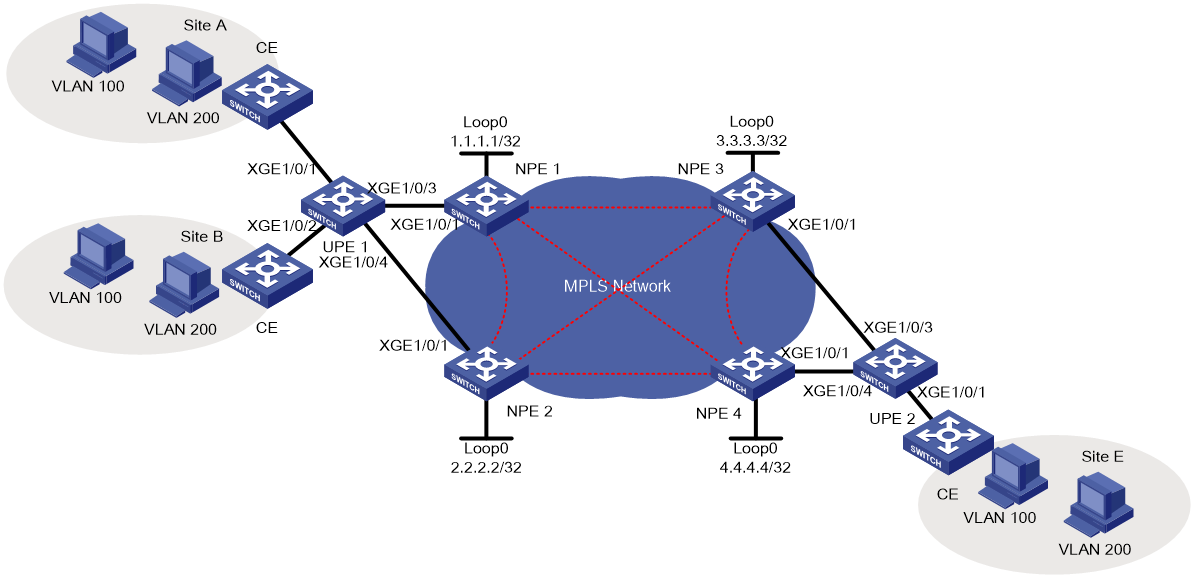
Analysis
· On the downlink port of each UPE, configure QinQ for NPEs identify user traffic by outer label.
· Use STP to provide loop protection and redundancy for the links.
· On the downlink port of each NPE, configure service instances to match user packets by outer label to transmit user packets over the associated PW.
· To negotiate inner labels, establish remote LDP peer relationships between any two NPEs.
Applicable hardware and software versions
Table 5 Applicable hardware and software versions
|
Hardware |
Software version |
|
S6812 series S6813 series |
Release 6628Pxx series |
|
S6550XE-HI series |
Release 8106Pxx |
|
S6525XE-HI series |
Release 8106Pxx |
|
S5850 series |
Unsupported |
|
S5570S-EI series |
Unsupported |
|
S5560X-EI series |
Release 6628Pxx |
|
S5560X-HI series |
Release 6628Pxx |
|
S5500V2-EI series |
Release 6628Pxx series |
|
MS4520V2-30F |
Release 6628Pxx series |
|
MS4520V2-30C MS4520V2-54C |
Release 6628Pxx series |
|
MS4520V2-28S MS4520V2-24TP |
Unsupported |
|
S6520X-HI series S6520X-EI series |
Release 6628Pxx series |
|
S6520X-SI series S6520-SI series |
Release 6628Pxx series |
|
S5000-EI series |
Release 6628Pxx series |
|
MS4600 series |
Release 6628Pxx series |
|
ES5500 series |
Release 6628Pxx series |
|
S5560S-EI series S5560S-SI series |
Unsupported |
|
S5500V3-24P-SI S5500V3-48P-SI |
Unsupported |
|
S5500V3-SI series (excluding the S5500V3-24P-SI and S5500V3-48P-SI) |
Unsupported |
|
S5170-EI series |
Unsupported |
|
S5130S-HI series S5130S-EI series S5130S-SI series S5130S-LI series |
Unsupported |
|
S5120V2-SI series S5120V2-LI Series |
Unsupported |
|
S5120V3-EI series |
Unsupported |
|
S5120V3-36F-SI S5120V3-28P-HPWR-SI S5120V3-54P-PWR-SI |
Unsupported |
|
S5120V3-SI series (excluding S5120V3-36F-SI, S5120V3-28P-HPWR-SI, and S5120V3-54P-PWR-SI) |
Unsupported |
|
S5120V3-LI series |
Unsupported |
|
S3600V3-EI series |
Unsupported |
|
S3600V3-SI series |
Unsupported |
|
S3100V3-EI series S3100V3-SI series |
Unsupported |
|
S5110V2 series |
Unsupported |
|
S5110V2-SI series |
Unsupported |
|
S5000V3-EI series S5000V5-EI series |
Unsupported |
|
S5000E-X series S5000X-EI series |
Unsupported |
|
E128C E152C E500C series E500D series |
Unsupported |
|
MS4320V2 series MS4320V3 series MS4300V2 series MS4320 series MS4200 series |
Unsupported |
|
WS5850-WiNet series |
Unsupported |
|
WS5820-WiNet series WS5810-WiNet series |
Unsupported |
|
WAS6000 series |
Unsupported |
|
IE4300-12P-AC & IE4300-12P-PWR IE4300-M series IE4320 series |
Unsupported |
|
S5135S-EI series |
Unsupported |
Procedure
Configuring basic network settings
1. Configure IGP on the MPLS backbone network to ensure that all interfaces on NPEs are reachable to each other. (Details not shown.)
2. Configure basic MPLS and MPLS LDP on the backbone network to establish LDP LSPs. (Details not shown.)
3. Configure interfaces on each CE that connect to UPEs as a trunk port and permit packets from VLAN 100 and VLAN 200 to pass through with tags. (Details not shown.)
Configuring UPE 1
# Configure UPE1 to operate in PVST mode to avoid loops.
<UPE1> system-view
[UPE1] stp global enable
[UPE1] stp mode pvst
# Assign Ten-GigabitEthernet 1/0/1to access VLAN 1000 and enable QinQ on the interface.
[UPE1] vlan 1000
[UPE1-vlan1000] quit
[UPE1] interface ten-gigabitethernet 1/0/1
[UPE1-Ten-GigabitEthernet1/0/1] port access vlan 1000
[UPE1-Ten-GigabitEthernet1/0/1] qinq enable
[UPE1-Ten-GigabitEthernet1/0/1] quit
# Assign Ten-GigabitEthernet 1/0/2 to access VLAN 1000 and enable QinQ on the interface.
[UPE1] interface ten-gigabitethernet 1/0/2
[UPE1-Ten-GigabitEthernet1/0/2] port access vlan 1000
[UPE1-Ten-GigabitEthernet1/0/2] qinq enable
[UPE1-Ten-GigabitEthernet1/0/2] quit
# Configure Ten-GigabitEthernet 1/0/3 as a trunk port, and permit tagged packets from VLAN 1000 to be transmitted to NPE 1.
[UPE1] interface ten-gigabitethernet 1/0/3
[UPE1-Ten-GigabitEthernet1/0/3] port link-type trunk
[UPE1-Ten-GigabitEthernet1/0/3] port trunk permit vlan 1000
[UPE1-Ten-GigabitEthernet1/0/3] quit
# Configure Ten-GigabitEthernet 1/0/4 as a trunk port, and permit tagged packets from VLAN 1000 to be transmitted to NPE 2.
[UPE1] interface ten-gigabitethernet 1/0/4
[UPE1-Ten-GigabitEthernet1/0/4] port link-type trunk
[UPE1-Ten-GigabitEthernet1/0/4] port trunk permit vlan 1000
[UPE1-Ten-GigabitEthernet1/0/4] quit
Configuring NPE 1
# Enable MPLS L2VPN.
[NPE1] l2vpn enable
# Configure VSI user_a that uses LDP as the PW signaling protocol.
[NPE1] vsi user_a
[NPE1-vsi-user_a] pwsignaling ldp
# Specify NPE 2, NPE 3, and NPE 4 as the remote peers.
[NPE1-vsi-user_a-ldp] peer 2.2.2.2 pw-id 500
[NPE1-vsi-user_a-ldp-2.2.2.2-500] quit
[NPE1-vsi-user_a-ldp] peer 3.3.3.3 pw-id 500
[NPE1-vsi-user_a-ldp-3.3.3.3-500] quit
[NPE1-vsi-user_a-ldp] peer 4.4.4.4 pw-id 500
[NPE1-vsi-user_a-ldp-4.4.4.4-500] quit
[NPE1-vsi-user_a-ldp] quit
[NPE1-vsi-user_a] quit
# Create service instance 1000 on Ten-GigabitEthernet 1/0/1 that connects to UPE 1 to match packets from VLAN 1000 and bind the service instance to VSI user_a. Because upstream packets carry the service provider VLAN, the AC access mode must be VLAN (optional, defaulting to VLAN mode).
[NPE1] interface ten-gigabitethernet 1/0/1
[NPE1-Ten-GigabitEthernet1/0/1] service-instance 1000
[NPE1-Ten-GigabitEthernet1/0/1-srv1000] encapsulation s-vid 1000
[NPE1-Ten-GigabitEthernet1/0/1-srv1000] xconnect vsi user_a access-mode vlan
[NPE1-Ten-GigabitEthernet1/0/1-srv1000] quit
Configuring NPE 2
The configuration for NPE 2 is similar to that for NPE 1 except that the NPE peers for them are different. For more information about the configuration, see the configuration file.
Configuring UPE 2
# Configure UPE2 to operate in PVST mode to avoid loops.
<UPE2> system-view
[UPE2] stp global enable
[UPE2] stp mode pvst
# Assign Ten-GigabitEthernet 1/0/1to access VLAN 1000 and enable QinQ on the interface.
[UPE2] vlan 1000
[UPE2-vlan1000] quit
[UPE2] interface ten-gigabitethernet 1/0/1
[UPE2-Ten-GigabitEthernet1/0/1] port access vlan 1000
[UPE2-Ten-GigabitEthernet1/0/1] qinq enable
[UPE2-Ten-GigabitEthernet1/0/1] quit
# Configure Ten-GigabitEthernet 1/0/3 as a trunk port, and permit tagged packets from VLAN 1000 to be transmitted to NPE 3.
[UPE2] interface ten-gigabitethernet 1/0/3
[UPE2-Ten-GigabitEthernet1/0/3] port link-type trunk
[UPE2-Ten-GigabitEthernet1/0/3] port trunk permit vlan 1000
[UPE2-Ten-GigabitEthernet1/0/3] quit
# Configure Ten-GigabitEthernet 1/0/4 as a trunk port, and permit tagged packets from VLAN 1000 to be transmitted to NPE 4.
[UPE2] interface ten-gigabitethernet 1/0/4
[UPE2-Ten-GigabitEthernet1/0/4] port link-type trunk
[UPE2-Ten-GigabitEthernet1/0/4] port trunk permit vlan 1000
[UPE2-Ten-GigabitEthernet1/0/4] quit
Configuring NPE 3
# Enable MPLS L2VPN.
[NPE3] l2vpn enable
# Configure VSI user_a that uses LDP as the PW signaling protocol.
[NPE3] vsi user_a
[NPE3-vsi-user_a] pwsignaling ldp
# Specify NPE 1, NPE 2, and NPE 4 as the peer NPEs.
[NPE3-vsi-user_a-ldp] peer 1.1.1.1 pw-id 500
[NPE3-vsi-user_a-ldp-1.1.1.1-500] quit
[NPE3-vsi-user_a-ldp] peer 2.2.2.2 pw-id 500
[NPE3-vsi-user_a-ldp-2.2.2.2-500] quit
[NPE3-vsi-user_a-ldp] peer 4.4.4.4 pw-id 500
[NPE3-vsi-user_a-ldp-4.4.4.4-500] quit
[NPE3-vsi-user_a-ldp] quit
[NPE3-vsi-user_a] quit
# Create service instance 1000 on Ten-GigabitEthernet 1/0/1 of UPE 2 to match packets from VLAN 1000 and bind the service instance to VSI user_a. Because upstream packets carry the carrier's VLAN, the AC access mode must be VLAN (optional, defaulting to VLAN mode).
[NPE3] interface ten-gigabitethernet 1/0/1
[NPE3-Ten-GigabitEthernet1/0/1] service-instance 1000
[NPE3-Ten-GigabitEthernet1/0/1-srv1000] encapsulation s-vid 1000
[NPE3-Ten-GigabitEthernet1/0/1-srv1000] xconnect vsi user_a access-mode vlan
[NPE3-Ten-GigabitEthernet1/0/1-srv1000] quit
Configuring NPE 4
The configuration for NPE 4 is similar to that for NPE 3 except that the NPE peers for them are different. For more information about the configuration, see the configuration file.
Verifying the configuration
Verify the state of PWs on each NPE. The following uses NPE 1 as an example.
# Use the display l2vpn pw command on NPE 1 to view the PW state.
[NPE1] display l2vpn pw
Flags: M - main, B - backup, H - hub link, S - spoke link, N - no split horizon
Total number of PWs: 3, 3 up, 0 blocked, 0 down, 0 defect
VSI Name: user_a
Peer PW ID/Rmt Site In/Out Label Proto Flag Link ID State
2.2.2.2 500 131199/131199 LDP M 256 Up
3.3.3.3 500 131198/131198 LDP M 257 Up
4.4.4.4 500 131197/131197 LDP M 258 Up
# Use ping to identify whether hosts within the same VLAN but at different sites can reach each other. If the ping operation succeeds, the VPLS is created successfully.
Configuration files
Only the configuration file for H-VPLS is provided. The configuration for CEs and the routing protocol configuration between PEs are not shown.
· UPE 1
#
vlan 1000
#
interface Ten-GigabitEthernet1/0/1
port link-mode bridge
port access vlan 1000
qinq enable
#
interface Ten-GigabitEthernet1/0/2
port link-mode bridge
port access vlan 1000
qinq enable
#
interface Ten-GigabitEthernet1/0/3
port link-mode bridge
port link-type trunk
port trunk permit vlan 1 1000
#
interface Ten-GigabitEthernet1/0/4
port link-mode bridge
port link-type trunk
port trunk permit vlan 1 1000
#
· NPE 1
#
mpls lsr-id 1.1.1.1
#
mpls ldp
#
l2vpn enable
#
vsi user_a
pwsignaling ldp
peer 2.2.2.2 pw-id 500
peer 3.3.3.3 pw-id 500
peer 4.4.4.4 pw-id 500
#
interface Ten-GigabitEthernet1/0/1
port link-mode bridge
service-instance 1000
encapsulation s-vid 1000
xconnect vsi user_a
#
· NPE 2
#
mpls lsr-id 2.2.2.2
#
mpls ldp
#
l2vpn enable
#
vsi user_a
pwsignaling ldp
peer 1.1.1.1 pw-id 500
peer 3.3.3.3 pw-id 500
peer 4.4.4.4 pw-id 500
#
interface Ten-GigabitEthernet1/0/1
port link-mode bridge
service-instance 1000
encapsulation s-vid 1000
xconnect vsi user_a
#
#
vlan 1000
#
interface Ten-GigabitEthernet1/0/1
port link-mode bridge
port access vlan 1000
qinq enable
#
interface Ten-GigabitEthernet1/0/3
port link-mode bridge
port link-type trunk
port trunk permit vlan 1 1000
#
interface Ten-GigabitEthernet1/0/4
port link-mode bridge
port link-type trunk
port trunk permit vlan 1 1000
#
· NPE 3
#
mpls lsr-id 3.3.3.3
#
mpls ldp
#
l2vpn enable
#
vsi user_a
pwsignaling ldp
peer 1.1.1.1 pw-id 500
peer 2.2.2.2 pw-id 500
peer 4.4.4.4 pw-id 500
#
interface Ten-GigabitEthernet1/0/1
port link-mode bridge
service-instance 1000
encapsulation s-vid 1000
xconnect vsi user_a
#
· NPE 4
#
mpls lsr-id 4.4.4.4
#
mpls ldp
#
l2vpn enable
#
vsi user_a
pwsignaling ldp
peer 1.1.1.1 pw-id 500
peer 2.2.2.2 pw-id 500
peer 3.3.3.3 pw-id 500
#
interface Ten-GigabitEthernet1/0/1
port link-mode bridge
service-instance 1000
encapsulation s-vid 1000
xconnect vsi user_a
#