- Table of Contents
-
- H3C Fixed Port Campus Switches Configuration Examples-6W105
- 00-Applicable hardware and software versions
- 01-Login Management Configuration Examples
- 02-RBAC Configuration Examples
- 03-Software Upgrade Examples
- 04-ISSU Configuration Examples
- 05-Software Patching Examples
- 06-Ethernet Link Aggregation Configuration Examples
- 07-Port Isolation Configuration Examples
- 08-Spanning Tree Configuration Examples
- 09-VLAN Configuration Examples
- 10-VLAN Tagging Configuration Examples
- 11-DHCP Snooping Configuration Examples
- 12-Cross-Subnet Dynamic IP Address Allocation Configuration Examples
- 13-IPv6 over IPv4 Tunneling with OSPFv3 Configuration Examples
- 14-IPv6 over IPv4 GRE Tunnel Configuration Examples
- 15-GRE with OSPF Configuration Examples
- 16-OSPF Configuration Examples
- 17-IS-IS Configuration Examples
- 18-BGP Configuration Examples
- 19-Policy-Based Routing Configuration Examples
- 20-OSPFv3 Configuration Examples
- 21-IPv6 IS-IS Configuration Examples
- 22-Routing Policy Configuration Examples
- 23-IGMP Snooping Configuration Examples
- 24-IGMP Configuration Examples
- 25-MLD Snooping Configuration Examples
- 26-IPv6 Multicast VLAN Configuration Examples
- 27-ACL Configuration Examples
- 28-Traffic Policing Configuration Examples
- 29-GTS and Rate Limiting Configuration Examples
- 30-Traffic Filtering Configuration Examples
- 31-AAA Configuration Examples
- 32-Port Security Configuration Examples
- 33-Portal Configuration Examples
- 34-SSH Configuration Examples
- 35-IP Source Guard Configuration Examples
- 36-Ethernet OAM Configuration Examples
- 37-CFD Configuration Examples
- 38-DLDP Configuration Examples
- 39-VRRP Configuration Examples
- 40-BFD Configuration Examples
- 41-NTP Configuration Examples
- 42-SNMP Configuration Examples
- 43-NQA Configuration Examples
- 44-Mirroring Configuration Examples
- 45-sFlow Configuration Examples
- 46-OpenFlow Configuration Examples
- 47-MAC Address Table Configuration Examples
- 48-Static Multicast MAC Address Entry Configuration Examples
- 49-IP Unnumbered Configuration Examples
- 50-MVRP Configuration Examples
- 51-MCE Configuration Examples
- 52-Attack Protection Configuration Examples
- 53-Smart Link Configuration Examples
- 54-RRPP Configuration Examples
- 55-BGP Route Selection Configuration Examples
- 56-IS-IS Route Summarization Configuration Examples
- 57-VXLAN Configuration Examples
- 58-DRNI Configuration Examples
- 59-IRF 3.1 Configuration Examples
- 60-PTP Configuration Examples
- 61-S-MLAG Configuration Examples
- 62-Puppet Configuration Examples
- 63-802.1X Configuration Examples
- 64-MAC Authentication Configuration Examples
- 65-ISATAP Tunnel and 6to4 Tunnel Configuration Examples
- 66-BIDIR-PIM Configuration Examples
- 67-Congestion Avoidance and Queue Scheduling Configuration Examples
- 68-Basic MPLS Configuration Examples
- 69-MPLS L3VPN Configuration Examples
- 70-MPLS OAM Configuration Examples
- 71-EVPN-DCI over an MPLS L3VPN Network Configuration Examples
- 72-DRNI and EVPN Configuration Examples
- 73-Multicast VPN Configuration Examples
- 74-MPLS TE Configuration Examples
- 75-Control Plane-Based QoS Policy Configuration Examples
- 76-Priority Mapping and Queue Scheduling Configuration Examples
- 77-ARP Attack Protection Configuration Examples
- 78-IRF Software Upgrade Configuration Examples
- 79-IRF Member Replacement Configuration Examples
- 80-Layer 3 Multicast on Multicast Source-Side DR System Configuration Examples
- 81-EVPN Multicast Configuration Examples
- 82-Priority Marking and Queue Scheduling Configuration Examples
- 83-EAA Configuration Examples
- 84-GRE Tunnel Access to MPLS L3VPN Configuration Examples
- 85-MC-NAT Configuration Examples
- 86-M-LAG Configuration Examples (Applicable to M-LAG Versions)
- 87-MOD Configuration Examples
- 88-MPLS L2VPN Configuration Examples
- 89-VPLS Configuration Examples
- 90-SR-MPLS Configuration Examples
- 91-VCF Fabric Configuration Examples
- 92-NetStream Configuration Examples
- 93-Configuration Example for Software Upgrade with Zero Packet Loss by Using GIR in VXLAN M-LAG Network
- 94-Configuration Example for Software Upgrade with Zero Packet Loss by Using GIR in VXLAN DRNI Network
- Related Documents
-
87-MOD Configuration Examples
General restrictions and guidelines
Example: Configuring simple MOD
Applicable hardware and software versions
Configuring Device B, Device C, Device D, and Device E
Verifying the configuration on Device A
Verifying the configuration on Device B, Device C, Device D, and Device E
Analyzing MOD packets received by the collector
Introduction
Mirror On Drop (MOD) can detect packet drops during the forwarding process on the device. When a packet is dropped, MOD can send the packet drop reason and the characteristics of the dropped packet to the collector.
This document provides examples for configuring MOD.
Prerequisites
The configuration examples in this document were created and verified in a lab environment, and all the devices were started with the factory default configuration. When you are working on a live network, make sure you understand the potential impact of every command on your network.
This document assumes that you have basic knowledge of MOD.
General restrictions and guidelines
When you configure MOD follow these restrictions and guidelines:
· Only one ACL can be specified for a flow group.
· Because a flow can belong to only one flow group, make sure the same flow is not assigned to more than one flow group when specifying ACLs.
· MOD takes effect only on packets matching ACLs referenced by flow groups.
· To delete an applied flow group, first remove the application and then delete the flow group.
· You cannot modify the name or mode of an existing flow group.
Example: Configuring simple MOD
Network configuration
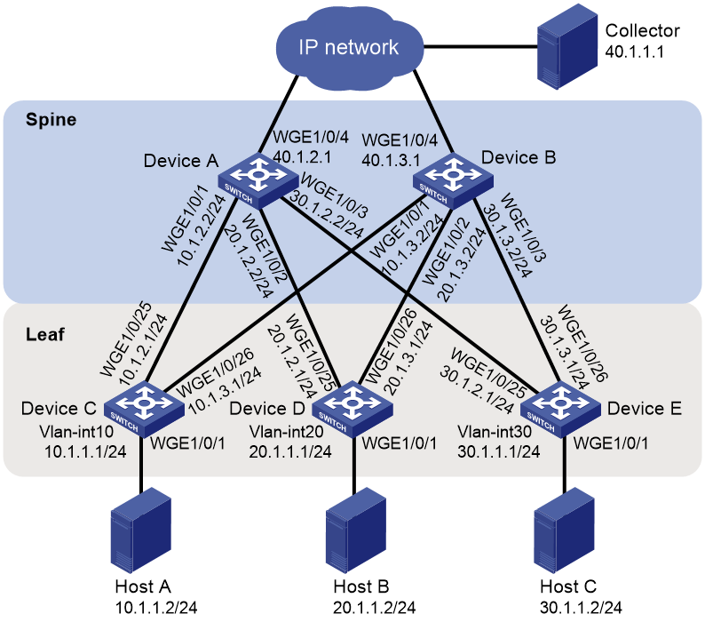
As shown in Figure 1, the network uses a spine-leaf architecture. Configure simple MOD on the spine device and leaf devices to identify whether packets are dropped during the forwarding process on the devices.
Analysis
To generate flow entries based on the flow group, configure the flow group mode to simple MOD.
Configure simple MOD to monitor packet drops based on the reason list.
Applicable hardware and software versions
The following matrix shows the hardware and software versions to which this configuration example is applicable:
|
Hardware |
Software version |
|
S6812 switch series S6813 switch series |
Not supported |
|
S6550XE-HI switch series |
Release 8106Pxx |
|
S6525XE-HI switch series |
Release 8106Pxx |
|
S5850 switch series |
Not supported |
|
S5570S-EI switch series |
Not supported |
|
S5560X-EI switch series |
Not supported |
|
S5560X-HI switch series |
Not supported |
|
S5500V2-EI switch series |
Not supported |
|
MS4520V2-30F switch |
Not supported |
|
MS4520V2-30C switch MS4520V2-54C switch |
Not supported |
|
MS4520V2-28S switch MS4520V2-24TP switch |
Not supported |
|
S6520X-HI switch series S6520X-EI switch series |
Not supported |
|
S6520X-SI switch series S6520-SI switch series |
Not supported |
|
S5000-EI switch series |
Not supported |
|
MS4600 switch series |
Not supported |
|
ES5500 switch series |
Not supported |
|
S5560S-EI switch series S5560S-SI switch series |
Not supported |
|
S5500V3-24P-SI switch S5500V3-48P-SI switch |
Not supported |
|
S5500V3-SI switch series (except S5500V3-24P-SI and S5500V3-48P-SI) |
Not supported |
|
S5170-EI switch series |
Not supported |
|
S5130S-HI switch series S5130S-EI switch series S5130S-SI switch series S5130S-LI switch series |
Not supported |
|
S5120V2-SI switch series S5120V2-LI switch series |
Not supported |
|
S5120V3-EI switch series |
Not supported |
|
S5120V3-36F-SI switch S5120V3-28P-HPWR-SI switch S5120V3-54P-PWR-SI switch |
Not supported |
|
S5120V3-SI switch series (except S5120V3-36F-SI, S5120V3-28P-HPWR-SI, and S5120V3-54P-PWR-SI) |
Not supported |
|
S5120V3-LI switch series |
Not supported |
|
S3600V3-EI switch series |
Not supported |
|
S3600V3-SI switch series |
Not supported |
|
S3100V3-EI switch series S3100V3-SI switch series |
Not supported |
|
S5110V2 switch series |
Not supported |
|
S5110V2-SI switch series |
Not supported |
|
S5000V3-EI switch series S5000V5-EI switch series |
Not supported |
|
S5000E-X switch series S5000X-EI switch series |
Not supported |
|
E128C switch E152C switch E500C switch series E500D switch series |
Not supported |
|
MS4320V2 switch series MS4320V3 switch series MS4300V2 switch series MS4320 switch series MS4200 switch series |
Not supported |
|
WS5850-WiNet switch series |
Not supported |
|
WS5820-WiNet switch series WS5810-WiNet switch series |
Not supported |
|
WAS6000 switch series |
Not supported |
|
IE4300-12P-AC IE4300-12P-PWR IE4300-M switch series IE4320 switch series |
Not supported |
|
IE4520 switch series |
Not supported |
|
S5135S-EI switch series |
Not supported |
Procedures
Configuring Device A
Configuring IP addresses for interfaces
# Configure interfaces Twenty-FiveGigE 1/0/1 through Twenty-FiveGigE 1/0/3 to operate in Layer 3 mode, and configure an IP address for each interface.
<DeviceA> system-view
[DeviceA] interface twenty-fivegige 1/0/1
[DeviceA-Twenty-FiveGigE1/0/1] port link-mode route
[DeviceA-Twenty-FiveGigE1/0/1] ip address 10.1.2.2 24
[DeviceA-Twenty-FiveGigE1/0/1] quit
[DeviceA] interface twenty-fivegige 1/0/2
[DeviceA-Twenty-FiveGigE1/0/2] port link-mode route
[DeviceA-Twenty-FiveGigE1/0/2] ip address 20.1.2.2 24
[DeviceA-Twenty-FiveGigE1/0/2] quit
[DeviceA] interface twenty-fivegige 1/0/3
[DeviceA-Twenty-FiveGigE1/0/3] port link-mode route
[DeviceA-Twenty-FiveGigE1/0/3] ip address 30.1.2.2 24
[DeviceA-Twenty-FiveGigE1/0/3] quit
Configuring a routing protocol
# Configure OSPF.
[DeviceA] ospf 1 router-id 1.1.1.1
[DeviceA-ospf-1] area 0
[DeviceA-ospf-1-area-0.0.0.0] network 10.1.2.0 0.0.0.255
[DeviceA-ospf-1-area-0.0.0.0] network 20.1.2.0 0.0.0.255
[DeviceA-ospf-1-area-0.0.0.0] network 30.1.2.0 0.0.0.255
[DeviceA-ospf-1-area-0.0.0.0] quit
[DeviceA-ospf-1] quit
Configuring a flow group
# Create advanced IPv4 ACL 3000, and configure a rule to match packets with destination IP address 10.0.0.10 for the ACL.
[DeviceA] acl advanced 3000
[DeviceA-acl-ipv4-adv-3000] rule permit ip destination 30.1.1.2 0
[DeviceA-acl-ipv4-adv-3000] quit
# Create flow group 2 in simple MOD mode and configure it to reference ACL 3000.
[DeviceA] telemetry flow-group 2 mode simple-mod
[DeviceA-telemetry-flow-group-2] if-match acl 3000
# Configure the flow group to generate flow entries based on the destination IP address.
[DeviceA-telemetry-flow-group-2] template destination-ip
[DeviceA-telemetry-flow-group-2] quit
# Set the flow entry aging time to 10 minutes.
[DeviceA] telemetry flow-group aging-time 10
# Apply flow group 2.
[DeviceA] telemetry apply flow-group 2
Configuring simple MOD
# Configure the device ID for simple MOD as 10.1.2.2.
[DeviceA] telemetry mod
[DeviceA-telemetry-mod] device-id 10.1.2.2
# Specify UDP for simple MOD to use to send packets to the collector.
[DeviceA-telemetry-mod] transport-protocol udp
# Encapsulate the packets sent to the collector by simple MOD with the following information: source IP address 10.1.2.2, destination IP address 40.1.1.1, source port number 1000, and destination port number 2333.
[DeviceA-telemetry-mod] collector source-ip 10.1.2.2 destination-ip 40.1.1.1 source-port 1000 destination-port 2333
# Configure simple MOD to monitor all packet drop reasons.
[DeviceA-telemetry-mod] reason-list all
[DeviceA-telemetry-mod] quit
[DeviceA] quit
Configuring Device B, Device C, Device D, and Device E
# Configure Device B, Device C, Device D, and Device E in the same way Device A is configured except for the following items:
· Interface IP addresses.
· OSPF router ID and network segments.
Device ID for simple MOD.
Source IP address encapsulated in the packets sent to the collector.
Verifying the configuration
Verifying the configuration on Device A
# Display the ACL configuration.
<DeviceA> display acl 3000
Advanced IPv4 ACL 3000, 1 rule,
ACL's step is 5, start ID is 0
rule 0 permit ip destination 30.1.1.2 0
# Display the flow group configuration.
<DeviceA> display telemetry flow-group 2
Flow group 2 (Successful)
ACL : 3000
Template : destination-ip
Mode : Simple MOD
Aging time: 10 minutes
Rate limit: -
Max-entry : -
# Display the simple MOD configuration.
<DeviceA> display telemetry mod
Status : Successful
Drop reason list:
ipv4-dip-miss
ip-multicast-error
unknown-vlan
tunnel-header-error
parity-error
higig-header-error
invalid-tpid
ipv6-dip-miss
Device ID : 10.1.2.2
Transport protocol : UDP
Collector
Source IP : 10.1.2.2
Destination IP : 40.1.1.1
Source port : 1000
Destination port : 2333
Verifying the configuration on Device B, Device C, Device D, and Device E
The configurations on Device B, Device C, Device D, and Device E are the same as the configuration on Device A except for interface IP addresses, OSPF configuration, the device ID for simple MOD, and the source IP address encapsulated in the packets sent to the collector. (Details not shown.)
Analyzing MOD packets received by the collector
# Ping Host C from Device A.
<DeviceA> ping 30.1.1.2
Ping 30.1.1.2 (30.1.1.2): 56 data bytes, press CTRL+C to break
56 bytes from 30.1.1.2: icmp_seq=0 ttl=255 time=4.703 ms
56 bytes from 30.1.1.2: icmp_seq=1 ttl=255 time=1.636 ms
56 bytes from 30.1.1.2: icmp_seq=2 ttl=255 time=1.733 ms
56 bytes from 30.1.1.2: icmp_seq=3 ttl=255 time=1.662 ms
56 bytes from 30.1.1.2: icmp_seq=4 ttl=255 time=1.606 ms
--- Ping statistics for 30.1.1.2 ---
5 packet(s) transmitted, 5 packet(s) received, 0.0% packet loss
round-trip min/avg/max/std-dev = 1.606/2.268/4.703/1.218 ms
# Modify the configuration of Device E.
<DeviceE> system-view
[DeviceE] ospf 1
[DeviceE-ospf-1] area 0
[DeviceE-ospf-1-area-0.0.0.0] undo network 30.1.2.0 0.0.0.255
[DeviceE-ospf-1-area-0.0.0.0] quit
[DeviceE-ospf-1] quit
# Ping Host C from Device A.
<DeviceA> ping 30.1.1.2
Ping 30.1.1.2 (30.1.1.2): 56 data bytes, press CTRL+C to break
Request time out
Request time out
Request time out
Request time out
Request time out
--- Ping statistics for 30.1.1.2 ---
5 packet(s) transmitted, 0 packet(s) received, 100.0% packet loss
When a packet destined for Host C is dropped during the forwarding process on the spine device and leaf devices, the collector can receive the packet drop reason and the characteristics of the dropped packet from the devices.
In this example, the packet drop information received by the collector showed that Device A dropped packets and the packet drop reason is ipv4-dip-miss. This indicates that there is no route on Device A to Host C. After you recover the OSPF configuration on Device E, Host C can receive the packets.
Configuration files
· Device A:
#
ospf 1 router-id 1.1.1.1
area 0.0.0.0
network 10.1.2.0 0.0.0.255
network 20.1.2.0 0.0.0.255
network 30.1.2.0 0.0.0.255
#
interface Twenty-FiveGigE1/0/1
port link-mode route
ip address 10.1.2.2 255.255.255.0
#
interface Twenty-FiveGigE1/0/2
port link-mode route
ip address 20.1.2.2 255.255.255.0
#
interface Twenty-FiveGigE1/0/3
port link-mode route
ip address 30.1.2.2 255.255.255.0
#
acl advanced 3000
rule 0 permit ip destination 30.1.1.2 0
#
telemetry mod
reason-list all
device-id 10.1.2.2
collector source-ip 10.1.2.2 destination-ip 40.1.1.1 source-port 1000 destination-port 2333
#
telemetry flow-group 21 mode simple-mod
if-match acl 3000
template destination-ip
#
telemetry apply flow-group 2
telemetry flow-group aging-time 10
#
· Device B, Device C, Device D, and Device E:
The configurations on Device B, Device C, Device D, and Device E are the same as the configuration on Device A except for interface IP addresses, OSPF router ID and network segments, the device ID for simple MOD, and the source IP address encapsulated in the packets sent to the collector. (Details not shown.)