- Table of Contents
-
- H3C Fixed Port Campus Switches Configuration Examples-6W105
- 00-Applicable hardware and software versions
- 01-Login Management Configuration Examples
- 02-RBAC Configuration Examples
- 03-Software Upgrade Examples
- 04-ISSU Configuration Examples
- 05-Software Patching Examples
- 06-Ethernet Link Aggregation Configuration Examples
- 07-Port Isolation Configuration Examples
- 08-Spanning Tree Configuration Examples
- 09-VLAN Configuration Examples
- 10-VLAN Tagging Configuration Examples
- 11-DHCP Snooping Configuration Examples
- 12-Cross-Subnet Dynamic IP Address Allocation Configuration Examples
- 13-IPv6 over IPv4 Tunneling with OSPFv3 Configuration Examples
- 14-IPv6 over IPv4 GRE Tunnel Configuration Examples
- 15-GRE with OSPF Configuration Examples
- 16-OSPF Configuration Examples
- 17-IS-IS Configuration Examples
- 18-BGP Configuration Examples
- 19-Policy-Based Routing Configuration Examples
- 20-OSPFv3 Configuration Examples
- 21-IPv6 IS-IS Configuration Examples
- 22-Routing Policy Configuration Examples
- 23-IGMP Snooping Configuration Examples
- 24-IGMP Configuration Examples
- 25-MLD Snooping Configuration Examples
- 26-IPv6 Multicast VLAN Configuration Examples
- 27-ACL Configuration Examples
- 28-Traffic Policing Configuration Examples
- 29-GTS and Rate Limiting Configuration Examples
- 30-Traffic Filtering Configuration Examples
- 31-AAA Configuration Examples
- 32-Port Security Configuration Examples
- 33-Portal Configuration Examples
- 34-SSH Configuration Examples
- 35-IP Source Guard Configuration Examples
- 36-Ethernet OAM Configuration Examples
- 37-CFD Configuration Examples
- 38-DLDP Configuration Examples
- 39-VRRP Configuration Examples
- 40-BFD Configuration Examples
- 41-NTP Configuration Examples
- 42-SNMP Configuration Examples
- 43-NQA Configuration Examples
- 44-Mirroring Configuration Examples
- 45-sFlow Configuration Examples
- 46-OpenFlow Configuration Examples
- 47-MAC Address Table Configuration Examples
- 48-Static Multicast MAC Address Entry Configuration Examples
- 49-IP Unnumbered Configuration Examples
- 50-MVRP Configuration Examples
- 51-MCE Configuration Examples
- 52-Attack Protection Configuration Examples
- 53-Smart Link Configuration Examples
- 54-RRPP Configuration Examples
- 55-BGP Route Selection Configuration Examples
- 56-IS-IS Route Summarization Configuration Examples
- 57-VXLAN Configuration Examples
- 58-DRNI Configuration Examples
- 59-IRF 3.1 Configuration Examples
- 60-PTP Configuration Examples
- 61-S-MLAG Configuration Examples
- 62-Puppet Configuration Examples
- 63-802.1X Configuration Examples
- 64-MAC Authentication Configuration Examples
- 65-ISATAP Tunnel and 6to4 Tunnel Configuration Examples
- 66-BIDIR-PIM Configuration Examples
- 67-Congestion Avoidance and Queue Scheduling Configuration Examples
- 68-Basic MPLS Configuration Examples
- 69-MPLS L3VPN Configuration Examples
- 70-MPLS OAM Configuration Examples
- 71-EVPN-DCI over an MPLS L3VPN Network Configuration Examples
- 72-DRNI and EVPN Configuration Examples
- 73-Multicast VPN Configuration Examples
- 74-MPLS TE Configuration Examples
- 75-Control Plane-Based QoS Policy Configuration Examples
- 76-Priority Mapping and Queue Scheduling Configuration Examples
- 77-ARP Attack Protection Configuration Examples
- 78-IRF Software Upgrade Configuration Examples
- 79-IRF Member Replacement Configuration Examples
- 80-Layer 3 Multicast on Multicast Source-Side DR System Configuration Examples
- 81-EVPN Multicast Configuration Examples
- 82-Priority Marking and Queue Scheduling Configuration Examples
- 83-EAA Configuration Examples
- 84-GRE Tunnel Access to MPLS L3VPN Configuration Examples
- 85-MC-NAT Configuration Examples
- 86-M-LAG Configuration Examples (Applicable to M-LAG Versions)
- 87-MOD Configuration Examples
- 88-MPLS L2VPN Configuration Examples
- 89-VPLS Configuration Examples
- 90-SR-MPLS Configuration Examples
- 91-VCF Fabric Configuration Examples
- 92-NetStream Configuration Examples
- 93-Configuration Example for Software Upgrade with Zero Packet Loss by Using GIR in VXLAN M-LAG Network
- 94-Configuration Example for Software Upgrade with Zero Packet Loss by Using GIR in VXLAN DRNI Network
- Related Documents
-
90-SR-MPLS Configuration Examples
Example: Configuring SR-MPLS over LDP for network connections
Applicable hardware and software versions
Introduction
This document provides SR-MPLS configuration examples.
Segment Routing (SR) is a source routing technology. The source node selects a path for the packets, and then encodes the path in the packet header as an ordered list of segments. Each segment is identified by the segment identifier (SID). The SR nodes along the path forward the packets based on the SIDs in the packets. Only the source node needs to maintain the path status.
SR can operate with MPLS. In an MPLS network, SR uses MPLS labels as SIDs to forward packets on an LSP.
Prerequisites
The configuration examples were created and verified in a lab environment, and all the devices were started with the factory default configuration. When you are working on a live network, make sure you understand the potential impact of every command on your network.
The following information is provided based on the assumption that you have basic knowledge of SR-MPLS.
Example: Configuring SR-MPLS over LDP for network connections
Network configuration
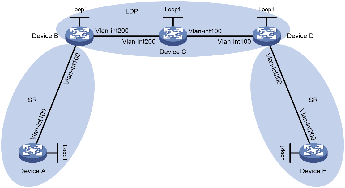
As shown in Figure 1, the SR-MPLS network is segmented by an LDP network. To enable communication between the two SR-MPLS network segments across the LDP network, establish label connectivity between the SR-MPLS and LDP networks. When Device A forwards traffic to Device E through the related SRLSP, you must configure both Device B and Device D to ensure that the two SR-MPLS network segments can communicate across the LDP network.
|
Device |
Interface |
IP address |
Device |
Interface |
IP address |
|
Device A |
Loop1 |
1.1.1.1/32 |
Device B |
Loop1 |
2.2.2.2/32 |
|
|
Vlan-Int100 |
10.0.0.1/24 |
|
Vlan-Int100 |
10.0.0.2/24 |
|
Device C |
Loop1 |
3.3.3.3/32 |
|
Vlan-Int200 |
11.0.0.1/24 |
|
|
Vlan-Int100 |
12.0.0.1/24 |
Device D |
Loop1 |
4.4.4.4/32 |
|
|
Vlan-Int200 |
11.0.0.2/24 |
|
Vlan-Int100 |
12.0.0.2/24 |
|
Device E |
Loop1 |
5.5.5.5/32 |
|
Vlan-Int200 |
13.0.0.1/24 |
|
|
Vlan-Int200 |
13.0.0.2/24 |
|
|
|
Analysis
· Configure Device A, Device B, Device C, Device D, and Device E to run IS-IS.
· Configure Device B, Device C, and Device D to run LDP.
· Configure Device A, Device B, Device D, and Device E to run SR-MPLS.
Applicable hardware and software versions
|
Product |
Software version |
|
S6812 switch series S6813 switch series |
Not supported |
|
S6550XE-HI switch series |
Release 8106Pxx |
|
S6525XE-HI switch series |
Release 8106Pxx |
|
S5850 switch series |
Not supported |
|
S5570S-EI switch series |
Not supported |
|
S5560X-EI switch series |
Not supported |
|
S5560X-HI switch series |
Not supported |
|
S5500V2-EI switch series |
Not supported |
|
MS4520V2-30F switch |
Not supported |
|
MS4520V2-30C switch MS4520V2-54C switch |
Not supported |
|
MS4520V2-28S switch MS4520V2-24TP switch |
Not supported |
|
S6520X-HI switch series S6520X-EI switch series |
Not supported |
|
S6520X-SI switch series S6520-SI switch series |
Not supported |
|
S5000-EI switch series |
Not supported |
|
MS4600 switch series |
Not supported |
|
ES5500 switch series |
Not supported |
|
S5560S-EI switch series S5560S-SI switch series |
Not supported |
|
S5500V3-24P-SI switch S5500V3-48P-SI switch |
Not supported |
|
S5500V3-SI switch series (except S5500V3-24P-SI and S5500V3-48P-SI) |
Not supported |
|
S5170-EI switch series |
Not supported |
|
S5130S-HI switch series S5130S-EI switch series S5130S-SI switch series S5130S-LI switch series |
Not supported |
|
S5120V2-SI switch series S5120V2-LI switch series |
Not supported |
|
S5120V3-EI switch series |
Not supported |
|
S5120V3-36F-SI switch S5120V3-28P-HPWR-SI switch S5120V3-54P-PWR-SI switch |
Not supported |
|
S5120V3-SI switch series (except S5120V3-36F-SI, S5120V3-28P-HPWR-SI, and S5120V3-54P-PWR-SI) |
Not supported |
|
S5120V3-LI switch series |
Not supported |
|
S3600V3-EI switch series |
Not supported |
|
S3600V3-SI switch series |
Not supported |
|
S3100V3-EI switch series S3100V3-SI switch series |
Not supported |
|
S5110V2 switch series |
Not supported |
|
S5110V2-SI switch series |
Not supported |
|
S5000V3-EI switch series S5000V5-EI switch series |
Not supported |
|
S5000E-X switch series S5000X-EI switch series |
Not supported |
|
E128C switch E152C switch E500C switch series E500D switch series |
Not supported |
|
MS4320V2 switch series MS4320V3 switch series MS4300V2 switch series MS4320 switch series MS4200 switch series |
Not supported |
|
WS5850-WiNet switch series |
Not supported |
|
WS5820-WiNet switch series WS5810-WiNet switch series |
Not supported |
|
WAS6000 switch series |
Not supported |
|
IE4300-12P-AC switch IE4300-12P-PWR switch IE4300-M switch series IE4320 switch series |
Not supported |
|
S5135S-EI switch series |
Not supported |
Procedures
Configuring Device A
# Configure IP addresses and masks for interfaces. (Details not shown.)
# Configure IS-IS to achieve network level connectivity and set the IS-IS cost style to wide.
<DeviceA> system-view
[DeviceA] isis 1
[DeviceA-isis-1] network-entity 00.0000.0000.0001.00
[DeviceA-isis-1] cost-style wide
[DeviceA-isis-1] quit
[DeviceA] interface vlan-interface 100
[DeviceA-Vlan-interface100] isis enable 1
[DeviceA-Vlan-interface100] quit
[DeviceA] interface loopback 1
[DeviceA-LoopBack1] isis enable 1
[DeviceA-LoopBack1] quit
# Configure an MPLS LSR ID.
[DeviceA] mpls lsr-id 1.1.1.1
# Enable SR-MPLS for IS-IS.
[DeviceA] isis 1
[DeviceA-isis-1] address-family ipv4
[DeviceA-isis-1-ipv4] segment-routing mpls
[DeviceA-isis-1-ipv4] quit
# Configure an MPLS SRGB.
[DeviceA-isis-1] segment-routing global-block 16000 16999
[DeviceA-isis-1] quit
# Configure an IS-IS prefix SID.
[DeviceA] interface loopback 1
[DeviceA-LoopBack1] isis prefix-sid index 10
[DeviceA-LoopBack1] quit
Configuring Device B
# Configure IP addresses and masks for interfaces. (Details not shown.)
# Configure IS-IS to achieve network level connectivity and set the IS-IS cost style to wide.
<DeviceB> system-view
[DeviceB] isis 1
[DeviceB-isis-1] network-entity 00.0000.0000.0002.00
[DeviceB-isis-1] cost-style wide
[DeviceB-isis-1] quit
[DeviceB] interface vlan-interface 100
[DeviceB-Vlan-interface100] isis enable 1
[DeviceB-Vlan-interface100] quit
[DeviceB] interface vlan-interface 200
[DeviceB-Vlan-interface200] isis enable 1
[DeviceB-Vlan-interface200] quit
[DeviceB] interface loopback 1
[DeviceB-LoopBack1] isis enable 1
[DeviceB-LoopBack1] quit
# Configure an MPLS LSR ID.
[DeviceB] mpls lsr-id 2.2.2.2
# Configure LDP.
[DeviceB] mpls ldp
[DeviceB-ldp] quit
[DeviceB] interface vlan-interface 200
[DeviceB-Vlan-interface200] mpls enable
[DeviceB-Vlan-interface200] mpls ldp enable
[DeviceB-Vlan-interface200] quit
# Enable SR-MPLS for IS-IS.
[DeviceB] isis 1
[DeviceB-isis-1] address-family ipv4
[DeviceB-isis-1-ipv4] segment-routing mpls
[DeviceB-isis-1-ipv4] quit
# Configure an MPLS SRGB.
[DeviceB-isis-1] segment-routing global-block 17000 17999
[DeviceB-isis-1] quit
# Configure an IS-IS prefix SID.
[DeviceB] interface loopback 1
[DeviceB-LoopBack1] isis prefix-sid index 20
[DeviceB-LoopBack1] quit
Configuring Device C
# Configure IP addresses and masks for interfaces. (Details not shown.)
# Configure IS-IS to achieve network level connectivity and set the IS-IS cost style to wide.
<DeviceC> system-view
[DeviceC] isis 1
[DeviceC-isis-1] network-entity 00.0000.0000.0003.00
[DeviceC-isis-1] cost-style wide
[DeviceC-isis-1] quit
[DeviceC] interface vlan-interface 100
[DeviceC-Vlan-interface100] isis enable 1
[DeviceC-Vlan-interface100] quit
[DeviceC] interface vlan-interface 200
[DeviceC-Vlan-interface200] isis enable 1
[DeviceC-Vlan-interface200] quit
[DeviceC] interface loopback 1
[DeviceC-LoopBack1] isis enable 1
[DeviceC-LoopBack1] quit
# Configure an MPLS LSR ID.
[DeviceC] mpls lsr-id 3.3.3.3
# Configure LDP.
[DeviceC] mpls ldp
[DeviceC-ldp] quit
[DeviceC] interface vlan-interface 100
[DeviceC-Vlan-interface100] mpls enable
[DeviceC-Vlan-interface100] mpls ldp enable
[DeviceC-Vlan-interface100] quit
[DeviceC] interface vlan-interface 200
[DeviceC-Vlan-interface200] mpls enable
[DeviceC-Vlan-interface200] mpls ldp enable
[DeviceC-Vlan-interface200] quit
Configuring Device D
# Configure IP addresses and masks for interfaces. (Details not shown.)
# Configure IS-IS to achieve network level connectivity and set the IS-IS cost style to wide.
<DeviceD> system-view
[DeviceD] isis 1
[DeviceD-isis-1] network-entity 00.0000.0000.0004.00
[DeviceD-isis-1] cost-style wide
[DeviceD-isis-1] quit
[DeviceD] interface vlan-interface 100
[DeviceD-Vlan-interface100] isis enable 1
[DeviceD-Vlan-interface100] quit
[DeviceD] interface vlan-interface 200
[DeviceD-Vlan-interface200] isis enable 1
[DeviceD-Vlan-interface200] quit
[DeviceD] interface loopback 1
[DeviceD-LoopBack1] isis enable 1
[DeviceD-LoopBack1] quit
# Configure an MPLS LSR ID.
[DeviceD] mpls lsr-id 4.4.4.4
# Configure LDP.
[DeviceD] mpls ldp
[DeviceD-ldp] quit
[DeviceD] interface vlan-interface 100
[DeviceD-Vlan-interface1001] mpls enable
[DeviceD-Vlan-interface100] mpls ldp enable
[DeviceD-Vlan-interface100] quit
# Enable SR-MPLS for IS-IS.
[DeviceD] isis 1
[DeviceD-isis-1] address-family ipv4
[DeviceD-isis-1-ipv4] segment-routing mpls
[DeviceD-isis-1-ipv4] quit
# Configure an MPLS SRGB.
[DeviceD-isis-1] segment-routing global-block 18000 18999
[DeviceD-isis-1] quit
# Configure an IS-IS prefix SID.
[DeviceD] interface loopback 1
[DeviceD-LoopBack1] isis prefix-sid index 40
[DeviceD-LoopBack1] quit
Configuring Device E
# Configure IP addresses and masks for interfaces. (Details not shown.)
# Configure IS-IS to achieve network level connectivity and set the IS-IS cost style to wide.
<DeviceE> system-view
[DeviceE] isis 1
[DeviceE-isis-1] network-entity 00.0000.0000.0005.00
[DeviceE-isis-1] cost-style wide
[DeviceE-isis-1] quit
[DeviceE] interface vlan-interface 200
[DeviceE-Vlan-interface200] isis enable 1
[DeviceE-Vlan-interface200] quit
[DeviceE] interface loopback 1
[DeviceE-LoopBack1] isis enable 1
[DeviceE-LoopBack1] quit
# Configure an MPLS LSR ID.
[DeviceE] mpls lsr-id 5.5.5.5
# Enable SR-MPLS for IS-IS.
[DeviceE] isis 1
[DeviceE-isis-1] address-family ipv4
[DeviceE-isis-1-ipv4] segment-routing mpls
[DeviceE-isis-1-ipv4] quit
# Configure an MPLS SRGB.
[DeviceE-isis-1] segment-routing global-block 19000 19999
[DeviceE-isis-1] quit
# Configure an IS-IS prefix SID.
[DeviceE] interface loopback 1
[DeviceE-LoopBack1] isis prefix-sid index 50
[DeviceE-LoopBack1] quit
Verifying the configuration
# Display LDP LSP information on Device B.
[DeviceB] display mpls ldp lsp
Status Flags: * - stale, L - liberal, B - backup, N/A - unavailable
FECs: 5 Ingress: 3 Transit: 3 Egress: 2
FEC In/Out Label Nexthop OutInterface
1.1.1.1/32 24116/-
-/24117(L)
2.2.2.2/32 3/-
-/24120(L)
3.3.3.3/32 -/3 11.0.0.2 Vlan200
24121/3 11.0.0.2 Vlan200
4.4.4.4/32 -/24119 11.0.0.2 Vlan200
24118/24119 11.0.0.2 Vlan200
5.5.5.5/32 -/24118 11.0.0.2 Vlan200
24117/24118 11.0.0.2 Vlan200
# Display IS-IS SRLSP information on Device B.
[DeviceB] display mpls lsp protocol isis
FEC Proto In/Out Label Interface/Out NHLFE
1.1.1.1/32 ISIS 17010/3 Vlan100
1.1.1.1/32 ISIS -/3 Vlan100
2.2.2.2/32 ISIS 17020/- -
4.4.4.4/32 ISIS 17040/24119 Vlan200
4.4.4.4/32 ISIS -/24119 Vlan200
5.5.5.5/32 ISIS 17050/24118 Vlan200
5.5.5.5/32 ISIS -/24118 Vlan200
The output shows that the IS-IS SRLSP entries for Device D and Device E are using LDP outgoing labels.
Configuration files
Device A
#
isis 1
cost-style wide
segment-routing global-block 16000 16999
network-entity 00.0000.0000.0001.00
#
address-family ipv4 unicast
segment-routing mpls
#
mpls lsr-id 1.1.1.1
#
vlan 1
#
vlan 100
#
interface LoopBack1
ip address 1.1.1.1 255.255.255.255
isis enable 1
isis prefix-sid index 10
#
interface Vlan-interface100
ip address 10.0.0.1 255.255.255.0
isis enable 1
#
interface GigabitEthernet1/0/1
port link-mode bridge
port access vlan 100
combo enable fiber
#
Device B
#
isis 1
cost-style wide
segment-routing global-block 17000 17999
network-entity 00.0000.0000.0002.00
#
address-family ipv4 unicast
segment-routing mpls
#
mpls lsr-id 2.2.2.2
#
vlan 1
#
vlan 100
#
vlan 200
#
mpls ldp
#
interface LoopBack1
ip address 2.2.2.2 255.255.255.255
isis enable 1
isis prefix-sid index 20
#
interface Vlan-interface100
ip address 10.0.0.2 255.255.255.0
isis enable 1
#
interface Vlan-interface200
ip address 11.0.0.1 255.255.255.0
isis enable 1
mpls enable
mpls ldp enable
#
interface GigabitEthernet1/0/1
port link-mode bridge
port access vlan 100
combo enable fiber
#
interface GigabitEthernet1/0/2
port link-mode bridge
port access vlan 200
combo enable fiber
#
Device C
#
isis 1
cost-style wide
network-entity 00.0000.0000.0003.00
#
mpls lsr-id 3.3.3.3
#
vlan 1
#
vlan 100
#
vlan 200
#
mpls ldp
#
interface LoopBack1
ip address 3.3.3.3 255.255.255.255
isis enable 1
#
interface Vlan-interface100
ip address 12.0.0.1 255.255.255.0
isis enable 1
mpls enable
mpls ldp enable
#
interface Vlan-interface200
ip address 11.0.0.2 255.255.255.0
isis enable 1
mpls enable
mpls ldp enable
#
interface GigabitEthernet1/0/1
port link-mode bridge
port access vlan 200
combo enable fiber
#
interface GigabitEthernet1/0/2
port link-mode bridge
port access vlan 100
combo enable fiber
#
Device D
#
isis 1
cost-style wide
segment-routing global-block 18000 18999
network-entity 00.0000.0000.0004.00
#
address-family ipv4 unicast
segment-routing mpls
#
mpls lsr-id 4.4.4.4
#
vlan 1
#
vlan 100
#
vlan 200
#
mpls ldp
#
interface LoopBack1
ip address 4.4.4.4 255.255.255.255
isis enable 1
isis prefix-sid index 40
#
interface Vlan-interface100
ip address 12.0.0.2 255.255.255.0
isis enable 1
mpls enable
mpls ldp enable
#
interface Vlan-interface200
ip address 13.0.0.1 255.255.255.0
isis enable 1
#
interface GigabitEthernet1/0/1
port link-mode bridge
port access vlan 100
combo enable fiber
#
interface GigabitEthernet1/0/2
port link-mode bridge
port access vlan 200
combo enable fiber
#
Device E
#
isis 1
cost-style wide
segment-routing global-block 19000 19999
network-entity 00.0000.0000.0005.00
#
address-family ipv4 unicast
segment-routing mpls
#
mpls lsr-id 5.5.5.5
#
vlan 1
#
vlan 200
#
interface LoopBack1
ip address 5.5.5.5 255.255.255.255
isis enable 1
isis prefix-sid index 50
#
interface Vlan-interface200
ip address 13.0.0.2 255.255.255.0
isis enable 1
#
interface GigabitEthernet1/0/1
port link-mode bridge
port access vlan 200
combo enable fiber
#