- Table of Contents
-
- H3C Fixed Port Campus Switches Configuration Examples-6W105
- 00-Applicable hardware and software versions
- 01-Login Management Configuration Examples
- 02-RBAC Configuration Examples
- 03-Software Upgrade Examples
- 04-ISSU Configuration Examples
- 05-Software Patching Examples
- 06-Ethernet Link Aggregation Configuration Examples
- 07-Port Isolation Configuration Examples
- 08-Spanning Tree Configuration Examples
- 09-VLAN Configuration Examples
- 10-VLAN Tagging Configuration Examples
- 11-DHCP Snooping Configuration Examples
- 12-Cross-Subnet Dynamic IP Address Allocation Configuration Examples
- 13-IPv6 over IPv4 Tunneling with OSPFv3 Configuration Examples
- 14-IPv6 over IPv4 GRE Tunnel Configuration Examples
- 15-GRE with OSPF Configuration Examples
- 16-OSPF Configuration Examples
- 17-IS-IS Configuration Examples
- 18-BGP Configuration Examples
- 19-Policy-Based Routing Configuration Examples
- 20-OSPFv3 Configuration Examples
- 21-IPv6 IS-IS Configuration Examples
- 22-Routing Policy Configuration Examples
- 23-IGMP Snooping Configuration Examples
- 24-IGMP Configuration Examples
- 25-MLD Snooping Configuration Examples
- 26-IPv6 Multicast VLAN Configuration Examples
- 27-ACL Configuration Examples
- 28-Traffic Policing Configuration Examples
- 29-GTS and Rate Limiting Configuration Examples
- 30-Traffic Filtering Configuration Examples
- 31-AAA Configuration Examples
- 32-Port Security Configuration Examples
- 33-Portal Configuration Examples
- 34-SSH Configuration Examples
- 35-IP Source Guard Configuration Examples
- 36-Ethernet OAM Configuration Examples
- 37-CFD Configuration Examples
- 38-DLDP Configuration Examples
- 39-VRRP Configuration Examples
- 40-BFD Configuration Examples
- 41-NTP Configuration Examples
- 42-SNMP Configuration Examples
- 43-NQA Configuration Examples
- 44-Mirroring Configuration Examples
- 45-sFlow Configuration Examples
- 46-OpenFlow Configuration Examples
- 47-MAC Address Table Configuration Examples
- 48-Static Multicast MAC Address Entry Configuration Examples
- 49-IP Unnumbered Configuration Examples
- 50-MVRP Configuration Examples
- 51-MCE Configuration Examples
- 52-Attack Protection Configuration Examples
- 53-Smart Link Configuration Examples
- 54-RRPP Configuration Examples
- 55-BGP Route Selection Configuration Examples
- 56-IS-IS Route Summarization Configuration Examples
- 57-VXLAN Configuration Examples
- 58-DRNI Configuration Examples
- 59-IRF 3.1 Configuration Examples
- 60-PTP Configuration Examples
- 61-S-MLAG Configuration Examples
- 62-Puppet Configuration Examples
- 63-802.1X Configuration Examples
- 64-MAC Authentication Configuration Examples
- 65-ISATAP Tunnel and 6to4 Tunnel Configuration Examples
- 66-BIDIR-PIM Configuration Examples
- 67-Congestion Avoidance and Queue Scheduling Configuration Examples
- 68-Basic MPLS Configuration Examples
- 69-MPLS L3VPN Configuration Examples
- 70-MPLS OAM Configuration Examples
- 71-EVPN-DCI over an MPLS L3VPN Network Configuration Examples
- 72-DRNI and EVPN Configuration Examples
- 73-Multicast VPN Configuration Examples
- 74-MPLS TE Configuration Examples
- 75-Control Plane-Based QoS Policy Configuration Examples
- 76-Priority Mapping and Queue Scheduling Configuration Examples
- 77-ARP Attack Protection Configuration Examples
- 78-IRF Software Upgrade Configuration Examples
- 79-IRF Member Replacement Configuration Examples
- 80-Layer 3 Multicast on Multicast Source-Side DR System Configuration Examples
- 81-EVPN Multicast Configuration Examples
- 82-Priority Marking and Queue Scheduling Configuration Examples
- 83-EAA Configuration Examples
- 84-GRE Tunnel Access to MPLS L3VPN Configuration Examples
- 85-MC-NAT Configuration Examples
- 86-M-LAG Configuration Examples (Applicable to M-LAG Versions)
- 87-MOD Configuration Examples
- 88-MPLS L2VPN Configuration Examples
- 89-VPLS Configuration Examples
- 90-SR-MPLS Configuration Examples
- 91-VCF Fabric Configuration Examples
- 92-NetStream Configuration Examples
- 93-Configuration Example for Software Upgrade with Zero Packet Loss by Using GIR in VXLAN M-LAG Network
- 94-Configuration Example for Software Upgrade with Zero Packet Loss by Using GIR in VXLAN DRNI Network
- Related Documents
-
88-MPLS L2VPN Configuration Examples
Contents
Example: Configuring CCC-based MPLS L2VPN
Applicable hardware and software versions
Example: Configuring static MPLS L2VPN
Applicable hardware and software versions
Example: Configuring LDP-based MPLS L2VPN
Applicable hardware and software versions
Example: Configuring BGP-based MPLS L2VPN
Applicable hardware and software versions
Overview
MPLS L2VPN provides point-to-point and point-to-multipoint connections. This chapter describes only the MPLS L2VPN technologies that provide point-to-point connections. This document describes configuration examples for implementing MPLS L2VPN in the following ways:
· CCC
· Static
· LDP
· BGP
Prerequisites
The configuration examples were created and verified in a lab environment, and all the devices were started with the factory default configuration. When you are working on a live network, make sure you understand the potential impact of every command on your network.
The following information is provided based on the assumption that you have basic knowledge of MPLS L2VPN.
Restrictions and guidelines
Before you configure MPLS, you must change the device's operating mode by using the switch-mode command and restart the device for the following switches:
· S6812 series
· S6813 series
· S5560X-EI series
· S5560X-HI series
· S5500V2-EI series
· MS4520V2-30F
· MS4520V2-30C
· MS4520V2-54C
· S6520X-HI series
· S6520X-EI series
· S6520X-SI series
· S6520-SI series
· S5000-EI series
· MS4600 series
In a non-IRF environment, use the switch-mode 3 command to switch the device to MPLS mode.
In an IRF environment, use the switch-mode 4 command to switch the device to MPLS-IRF mode.
Example: Configuring CCC-based MPLS L2VPN
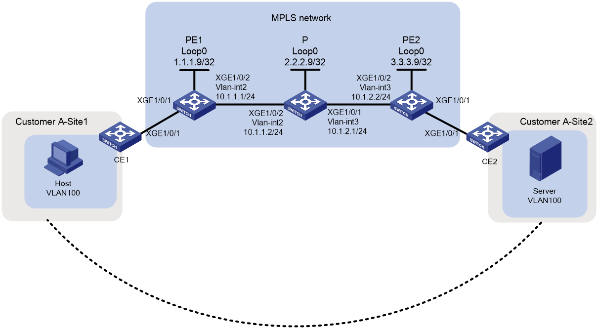
Network configuration
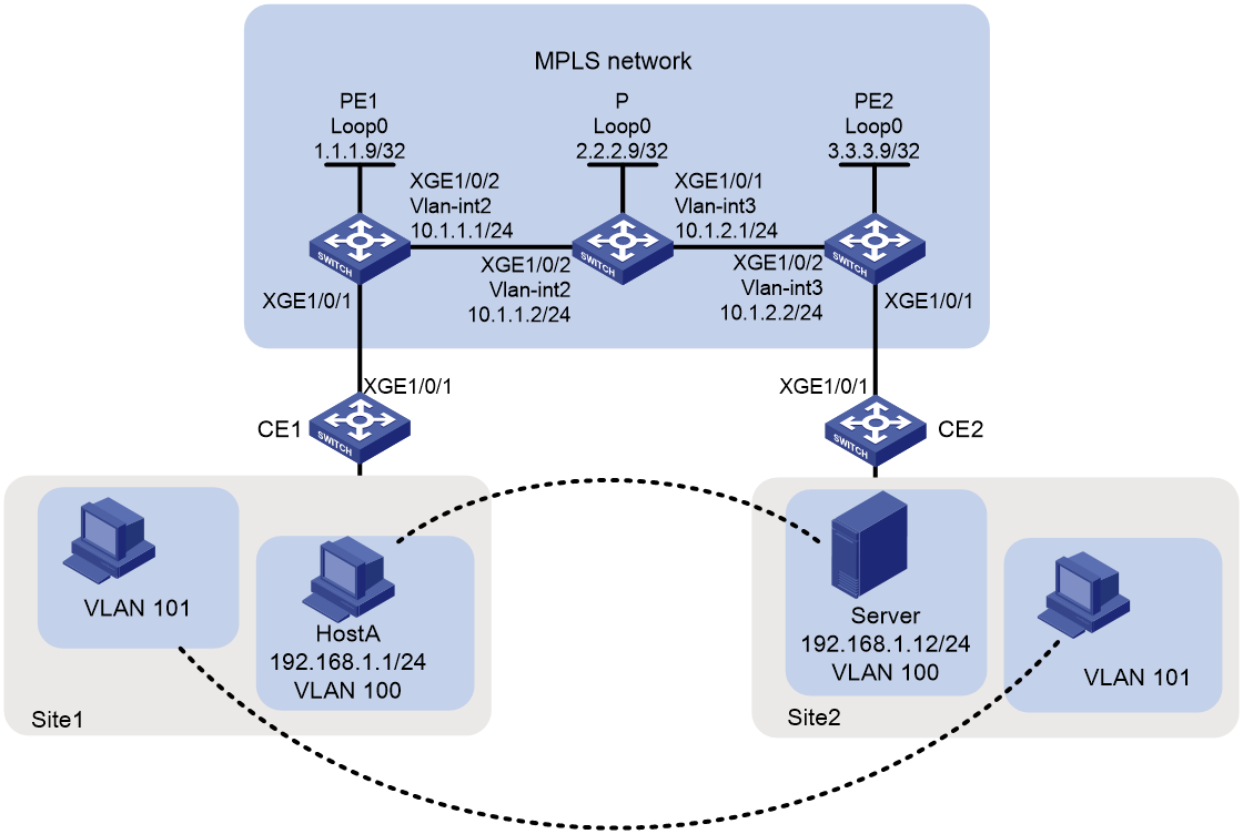
As shown in Figure 1, customer network sites Site1 and Site2, located at different physical locations, access the carrier MPLS network via devices CE1 and CE2, respectively. Users want host communication between the two sites to be unaware of the MPLS network's existence, as if both parties are in the same local area network (LAN). To achieve this, configure MPLS L2VPN using the CCC method to allow communication between VLAN 100 at Site1 and VLAN 100 at Site2, as well as between VLAN 101 at Site1 and VLAN 101 at Site2, while preventing communication between different VLANs.
Analysis
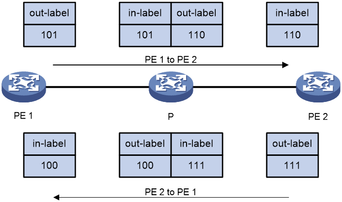
To establish an MPLS L2VPN connection by using the CCC mode, configure an ingress label and an egress label for each CCC connection on the PEs, and a bidirectional static LSP on the P device. The egress label must match the next hop's ingress label. Take the traffic of VLAN 100 as an example. As shown in Figure 2, in the direction from PE 1 to PE 2, PE 1's egress label and P's ingress label are 101, and P's egress label and PE 2's ingress label are 110. In the direction from PE 2 to PE 1, PE 2's egress label and P's ingress label are 111, and P's egress label and PE 1's ingress label are 100.
Figure 2 Label switching for VLAN100 traffic
Applicable hardware and software versions
Table 1 Applicable hardware and software versions
|
Hardware |
Software version |
|
S6812 series S6813 series |
Release 6628Pxx series |
|
S6550XE-HI series |
Release 8106Pxx |
|
S6525XE-HI series |
Release 8106Pxx |
|
S5850 series |
Unsupported |
|
S5570S-EI series |
Unsupported |
|
S5560X-EI series |
Release 6628Pxx |
|
S5560X-HI series |
Release 6628Pxx |
|
S5500V2-EI series |
Release 6628Pxx series |
|
MS4520V2-30F |
Release 6628Pxx series |
|
MS4520V2-30C MS4520V2-54C |
Release 6628Pxx series |
|
MS4520V2-28S MS4520V2-24TP |
Unsupported |
|
S6520X-HI series S6520X-EI series |
Release 6628Pxx series |
|
S6520X-SI series S6520-SI series |
Release 6628Pxx series |
|
S5000-EI series |
Release 6628Pxx series |
|
MS4600 series |
Release 6628Pxx series |
|
ES5500 series |
Release 6628Pxx series |
|
S5560S-EI series S5560S-SI series |
Unsupported |
|
S5500V3-24P-SI S5500V3-48P-SI |
Unsupported |
|
S5500V3-SI series (excluding the S5500V3-24P-SI and S5500V3-48P-SI) |
Unsupported |
|
S5170-EI series |
Unsupported |
|
S5130S-HI series S5130S-EI series S5130S-SI series S5130S-LI series |
Unsupported |
|
S5120V2-SI series S5120V2-LI Series |
Unsupported |
|
S5120V3-EI series |
Unsupported |
|
S5120V3-36F-SI S5120V3-28P-HPWR-SI S5120V3-54P-PWR-SI |
Unsupported |
|
S5120V3-SI series (excluding S5120V3-36F-SI, S5120V3-28P-HPWR-SI, and S5120V3-54P-PWR-SI) |
Unsupported |
|
S5120V3-LI series |
Unsupported |
|
S3600V3-EI series |
Unsupported |
|
S3600V3-SI series |
Unsupported |
|
S3100V3-EI series S3100V3-SI series |
Unsupported |
|
S5110V2 series |
Unsupported |
|
S5110V2-SI series |
Unsupported |
|
S5000V3-EI series S5000V5-EI series |
Unsupported |
|
S5000E-X series S5000X-EI series |
Unsupported |
|
E128C E152C E500C series E500D series |
Unsupported |
|
MS4320V2 series MS4320V3 series MS4300V2 series MS4320 series MS4200 series |
Unsupported |
|
WS5850-WiNet series |
Unsupported |
|
WS5820-WiNet series WS5810-WiNet series |
Unsupported |
|
WAS6000 series |
Unsupported |
|
IE4300-12P-AC & IE4300-12P-PWR IE4300-M series IE4320 series |
Unsupported |
|
S5135S-EI series |
Unsupported |
Procedure
Configuring interface attributes and enabling basic MPLS capabilities
· Configure PE 1:
# Configure an LSR ID.
<PE1> system-view
[PE1] interface loopback 0
[PE1-LoopBack0] ip address 1.1.1.9 32
[PE1-LoopBack0] quit
[PE1] mpls lsr-id 1.1.1.9
# Enable MPLS L2VPN globally.
[PE1] l2vpn enable
# Create VLAN 2 and add Ten-GigabitEthernet1/0/2 to VLAN 2.
[PE1] vlan 2
[PE1-vlan2] port Ten-GigabitEthernet 1/0/2
[PE1-vlan2] quit
# Create VLAN-interface 2 and enable MPLS on the interface.
[PE1] interface vlan-interface 2
[PE1-Vlan-interface2] ip address 10.1.1.1 24
[PE1-Vlan-interface2] mpls enable
[PE1-Vlan-interface2] quit
· Configure the P device:
# Configure an LSR ID.
<P> system-view
[P] interface loopback 0
[P-LoopBack0] ip address 2.2.2.9 32
[P-LoopBack0] quit
[P] mpls lsr-id 2.2.2.9
# Create VLAN 3 and add Ten-GigabitEthernet 1/0/1 to VLAN 3.
[P] vlan3
[P-vlan3] port Ten-GigabitEthernet1/0/1
[P-vlan3] quit
# Configure VLAN-interface 3 and enable MPLS on the interface.
[P] interface vlan-interface 3
[P-Vlan-interface3] ip address 10.1.2.1 24
[P-Vlan-interface3] mpls enable
[P-Vlan-interface3] quit
# Create VLAN 2 and add Ten-GigabitEthernet 1/0/2 to VLAN 2.
[P] vlan2
[P-vlan2] port Ten-GigabitEthernet1/0/2
[P-vlan2] quit
# Configure VLAN-interface 2 and enable MPLS on the interface.
[P] interface vlan-interface 2
[P-Vlan-interface2] ip address 10.1.1.2 24
[P-Vlan-interface2] mpls enable
[P-Vlan-interface2] quit
· Configure PE 2:
# Configure an LSR ID.
<PE2> system-view
[PE2] interface loopback 0
[PE2-LoopBack0] ip address 3.3.3.9 32
[PE2-LoopBack0] quit
[PE2] mpls lsr-id 3.3.3.9
# Enable MPLS L2VPN globally.
[PE2] l2vpn enable
# Create VLAN 3 and add Ten-GigabitEthernet 1/0/2 to VLAN 3.
[PE2] vlan 3
[PE2-vlan3] port Ten-GigabitEthernet 1/0/2
[PE2-vlan3] quit
# Configure VLAN-interface 3 and enable MPLS on the interface.
[PE2] interface vlan-interface 3
[PE2-Vlan-interface3] ip address 10.1.2.2 24
[PE2-Vlan-interface3] mpls enable
[PE2-Vlan-interface3] quit
Creating a CCC remote connection on a PE and configuring a static LSP on the P device
· Configure PE 1:
# Create service instance 100 on Ten-GigabitEthernet 1/0/1 to match packets with VLAN tag 100.
[PE1] interface ten-gigabitethernet1/0/1
[PE1-Ten-GigabitEthernet1/0/1] service-instance 100
[PE1-Ten-GigabitEthernet1/0/1-srv100] encapsulation s-vid 100
[PE1-Ten-GigabitEthernet1/0/1-srv100] quit
# Create service instance 101 on Ten-GigabitEthernet 1/0/1 to match packets with VLAN tag 101.
[PE1-Ten-GigabitEthernet1/0/1] service-instance 101
[PE1-Ten-GigabitEthernet1/0/1-srv101] encapsulation s-vid 101
[PE1-Ten-GigabitEthernet1/0/1-srv101] quit
[PE1-Ten-GigabitEthernet1/0/1] quit
# Create a cross-connect group named vpna and create a CCC remote connection named ccc with an incoming label of 100, an outgoing label of 101, and a next-hop address of 10.1.1.2 in the VPN. Bind service instance 100 on Ten-GigabitEthernet 1/0/1 to this CCC remote connection.
[PE1] xconnect-group vpna
[PE1-xcg-vpna] connection ccc
[PE1-xcg-vpna-ccc] ccc in-label 100 out-label 101 nexthop 10.1.1.2
[PE1-xcg-vpna-ccc] ac interface ten-gigabitethernet 1/0/1 service-instance 100
[PE1-xcg-vpna-ccc] quit
[PE1-xcg-vpna] quit
# Create a cross-connect group named vpnb and create a remote CCC connection named ccc with an incoming label of 200, an outgoing label of 201, and a next-hop address of 10.1.1.2 in the VPN. Bind service instance 100 on Ten-GigabitEthernet 1/0/1 to this remote CCC connection.
[PE1] xconnect-group vpnb
[PE1-xcg-vpnb] connection ccc
[PE1-xcg-vpnb-ccc] ccc in-label 200 out-label 201 nexthop 10.1.1.2
[PE1-xcg-vpnb-ccc] ac interface ten-gigabitethernet 1/0/1 service-instance 101
[PE1-xcg-vpnb-ccc] quit
[PE1-xcg-vpnb] quit
· Configure the P device:
# Configure a static LSP to forward packets from PE 1 to PE 2 that carry traffic from VLAN 100.
[P] static-lsp transit pe1-pe2-100 in-label 101 nexthop 10.1.2.2 out-label 110
# Configure a static LSP to forward packets from PE 1 to PE 2 that carry traffic from VLAN 101.
[P] static-lsp transit pe1-pe2-101 in-label 201 nexthop 10.1.2.2 out-label 210
# Configure a static LSP to forward packets from PE 2 to PE 1 that carry traffic from VLAN 100.
[P] static-lsp transit pe2-pe1-100 in-label 111 nexthop 10.1.1.1 out-label 100
# Configure a static LSP to forward packets from PE 2 to PE 1 that carry traffic from VLAN 101.
[P] static-lsp transit pe2-pe1-101 in-label 211 nexthop 10.1.1.1 out-label 200
· Configure PE 2:
# Create service instance 100 on Ten-GigabitEthernet 1/0/1 to match packets with VLAN tag 100.
[PE2] interface ten-gigabitethernet1/0/1
[PE2-Ten-GigabitEthernet1/0/1] service-instance 100
[PE2-Ten-GigabitEthernet1/0/1-srv100] encapsulation s-vid 100
[PE2-Ten-GigabitEthernet1/0/1-srv100] quit
# Create service instance 101 on Ten-GigabitEthernet 1/0/1 to match packets with VLAN tag 101.
[PE2-Ten-GigabitEthernet1/0/1] service-instance 101
[PE2-Ten-GigabitEthernet1/0/1-srv101] encapsulation s-vid 101
[PE2-Ten-GigabitEthernet1/0/1-srv101] quit
[PE2-Ten-GigabitEthernet1/0/1] quit
# Create a cross-connect group named vpna and create a remote CCC connection named ccc with an incoming label of 110, an outgoing label of 111, and a next-hop address of to 10.1.2.1 in the VPN. Bind service instance 100 on Ten-GigabitEthernet 1/0/1 to this remote CCC connection.
[PE2] xconnect-group vpna
[PE2-xcg-vpna] connection ccc
[PE2-xcg-vpna-ccc] ccc in-label 110 out-label 111 nexthop 10.1.2.1
[PE2-xcg-vpna-ccc] ac interface ten-gigabitethernet 1/0/1 service-instance 100
[PE2-xcg-vpna-ccc] quit
[PE2-xcg-vpna] quit
# Create a cross-connect group named vpnb and create a remote CCC connection named ccc with an incoming label of 210, an outgoing label of 211, and a next-hop address of 10.1.2.1 in the VPN. Bind service instance 101 on Ten-GigabitEthernet 1/0/1 to this remote CCC connection.
[PE2] xconnect-group vpnb
[PE2-xcg-vpnb] connection ccc
[PE2-xcg-vpnb-ccc] ccc in-label 210 out-label 211 nexthop 10.1.2.1
[PE2-xcg-vpnb-ccc] ac interface ten-gigabitethernet 1/0/1 service-instance 101
[PE2-xcg-vpnb-ccc] quit
[PE2-xcg-vpnb] quit
Connecting CEs to PEs
· Configure CE 1:
# Configure Ten-GigabitEthernet 1/0/1 as a trunk port and permit VLAN 100and VLAN 101.
<CE1> system-view
[CE1] vlan 100 to 101
[CE1] interface Ten-GigabitEthernet 1/0/1
[CE1-Ten-GigabitEthernet1/0/1] port link-type trunk
[CE1-Ten-GigabitEthernet1/0/1] port trunk permit vlan 100 101
· Configure CE 2:
# Configure Ten-GigabitEthernet 1/0/1 as a trunk port and permit VLAN 100and VLAN 101.
<CE2> system-view
[CE2] vlan 100 to 101
[CE2] interface Ten-GigabitEthernet 1/0/1
[CE2-Ten-GigabitEthernet1/0/1] port link-type trunk
[CE2-Ten-GigabitEthernet1/0/1] port trunk permit vlan 100 101
Verifying the configuration
# Display PW information on PE 1. The output shows that two PW connections have been established. The value for the PW ID/Rmt Site field is -, and the value for the Proto field is Static, indicating that the PW connections are remote CCC connections.
[PE1] display l2vpn pw
Flags: M - main, B - backup, H - hub link, S - spoke link, N - no split horizon
Total number of PWs: 2, 2 up, 0 blocked, 0 down, 0 defect
Xconnect-group Name: vpna
Peer PW ID/Rmt Site In/Out Label Proto Flag Link ID State
10.1.1.2 - 100/101 Static M 1 Up
Xconnect-group Name: vpnb
Peer PW ID/Rmt Site In/Out Label Proto Flag Link ID State
10.1.1.2 - 200/201 Static M 1 Up
# Verify that PW information can also be displayed on PE 2.
[PE2] display l2vpn pw
Flags: M - main, B - backup, H - hub link, S - spoke link, N - no split horizon
Total number of PWs: 2, 2 up, 0 blocked, 0 down, 0 defect
Xconnect-group Name: vpna
Peer PW ID/Rmt Site In/Out Label Proto Flag Link ID State
10.1.2.1 - 110/111 Static M 1 Up
Xconnect-group Name: vpnb
Peer PW ID/Rmt Site In/Out Label Proto Flag Link ID State
10.1.2.1 - 210/211 Static M 1 Up
# Use ping to identify whether host A and the server and hosts in VLAN 101 at the two sites can reach each other. If the ping operation succeeds, the L2VPN is established successfully.
Configuration files
· CE 1
#
vlan 100 to 101
#
interface Ten-GigabitEthernet1/0/1
port link-type trunk
port trunk permit vlan 100 to 101
#
· PE 1
mpls lsr-id 1.1.1.9
#
vlan 2
#
l2vpn enable
#
interface LoopBack0
ip address 1.1.1.9 255.255.255.255
#
interface Vlan-interface2
ip address 10.1.1.1 255.255.255.0
mpls enable
#
interface Ten-GigabitEthernet1/0/1
port link-mode bridge
service-instance 100
encapsulation s-vid 100
service-instance 101
encapsulation s-vid 101
#
interface Ten-GigabitEthernet1/0/2
port link-mode bridge
port access vlan 2
#
xconnect-group vpna
connection ccc
ac interface Ten-GigabitEthernet1/0/1 service-instance 100
ccc in-label 100 out-label 101 nexthop 10.1.1.2
#
xconnect-group vpnb
connection ccc
ac interface Ten-GigabitEthernet1/0/1 service-instance 101
ccc in-label 200 out-label 201 nexthop 10.1.1.2
#
· P
mpls lsr-id 2.2.2.9
#
vlan 2
#
vlan 3
#
interface LoopBack0
ip address 2.2.2.9 255.255.255.255
#
interface Vlan-interface2
ip address 10.1.1.2 255.255.255.0
mpls enable
#
interface Vlan-interface3
ip address 10.1.2.1 255.255.255.0
mpls enable
#
interface Ten-GigabitEthernet1/0/1
port link-mode bridge
port access vlan 3
#
interface Ten-GigabitEthernet1/0/2
port link-mode bridge
port access vlan 2
#
static-lsp transit pe1-pe2-100 in-label 101 nexthop 10.1.2.2 out-label 110
static-lsp transit pe1-pe2-101 in-label 201 nexthop 10.1.2.2 out-label 210
static-lsp transit pe2-pe1-100 in-label 111 nexthop 10.1.1.1 out-label 100
static-lsp transit pe2-pe1-101 in-label 211 nexthop 10.1.1.1 out-label 200
#
· PE 2
mpls lsr-id 3.3.3.9
#
vlan 3
#
l2vpn enable
#
interface LoopBack0
ip address 3.3.3.9 255.255.255.255
#
interface Vlan-interface3
ip address 10.1.2.2 255.255.255.0
mpls enable
#
interface Ten-GigabitEthernet1/0/1
port link-mode bridge
service-instance 100
encapsulation s-vid 100
service-instance 101
encapsulation s-vid 101
#
interface Ten-GigabitEthernet1/0/2
port link-mode bridge
port access vlan 3
#
xconnect-group vpna
connection ccc
ac interface Ten-GigabitEthernet1/0/1 service-instance 100
ccc in-label 110 out-label 111 nexthop 10.1.2.1
#
xconnect-group vpnb
connection ccc
ac interface Ten-GigabitEthernet1/0/1 service-instance 101
ccc in-label 210 out-label 211 nexthop 10.1.2.1
#
· CE 2
#
vlan 100 to 101
#
interface Ten-GigabitEthernet1/0/1
port link-mode bridge
port link-type trunk
port trunk permit vlan 100 to 101
#
Example: Configuring static MPLS L2VPN
Network configuration
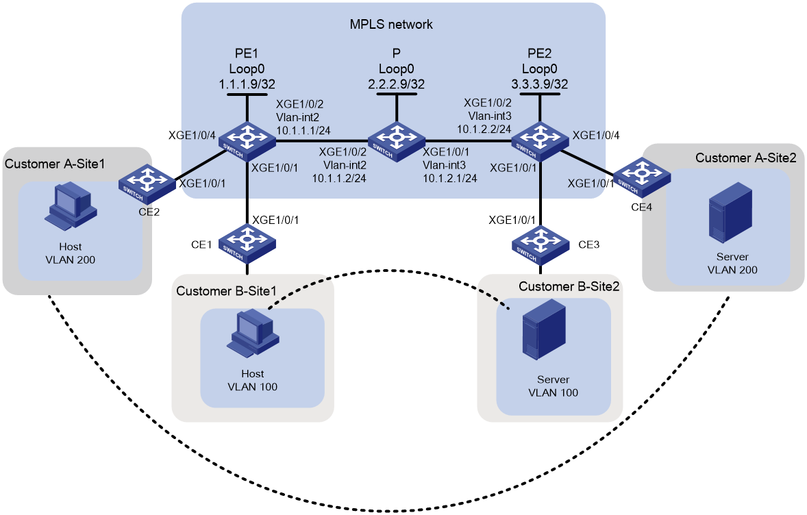
As shown in Figure 3, the MPLS network provides L2VPN services between different sites for User A and User B, with each user having only two fixed sites. Configure static MPLS L2VPN to enable communication between VLAN 200 of Site 1 and Site 2 for User A, and between VLAN 100 of Site 1 and Site 2 for User B.
Analysis
· Static MPLS L2VPN uses a two-layer label structure. In this example, the inner layer label is generated through manual configuration, and the outer layer label is dynamically generated by LDP.
· To ensure normal label exchange, make sure the incoming label configured at the local PE matches the outgoing label configured at the remote PE when you configure static connections for the same user. For User A, the outgoing label at Site 1 and the incoming label at Site 2 are 200, and the incoming label at Site 1 and the outgoing label at Site 2 are 201. For User B, the outgoing label at Site 1 and the incoming label at Site 2 are 100, and the incoming label at Site 1 and the outgoing label at Site 2 are 101.
Applicable hardware and software versions
Table 2 Applicable hardware and software versions
|
Hardware |
Software version |
|
S6812 series S6813 series |
Release 6628Pxx series |
|
S6550XE-HI series |
Release 8106Pxx |
|
S6525XE-HI series |
Release 8106Pxx |
|
S5850 series |
Unsupported |
|
S5570S-EI series |
Unsupported |
|
S5560X-EI series |
Release 6628Pxx |
|
S5560X-HI series |
Release 6628Pxx |
|
S5500V2-EI series |
Release 6628Pxx series |
|
MS4520V2-30F |
Release 6628Pxx series |
|
MS4520V2-30C MS4520V2-54C |
Release 6628Pxx series |
|
MS4520V2-28S MS4520V2-24TP |
Unsupported |
|
S6520X-HI series S6520X-EI series |
Release 6628Pxx series |
|
S6520X-SI series S6520-SI series |
Release 6628Pxx series |
|
S5000-EI series |
Release 6628Pxx series |
|
MS4600 series |
Release 6628Pxx series |
|
ES5500 series |
Release 6628Pxx series |
|
S5560S-EI series S5560S-SI series |
Unsupported |
|
S5500V3-24P-SI S5500V3-48P-SI |
Unsupported |
|
S5500V3-SI series (excluding the S5500V3-24P-SI and S5500V3-48P-SI) |
Unsupported |
|
S5170-EI series |
Unsupported |
|
S5130S-HI series S5130S-EI series S5130S-SI series S5130S-LI series |
Unsupported |
|
S5120V2-SI series S5120V2-LI Series |
Unsupported |
|
S5120V3-EI series |
Unsupported |
|
S5120V3-36F-SI S5120V3-28P-HPWR-SI S5120V3-54P-PWR-SI |
Unsupported |
|
S5120V3-SI series (excluding S5120V3-36F-SI, S5120V3-28P-HPWR-SI, and S5120V3-54P-PWR-SI) |
Unsupported |
|
S5120V3-LI series |
Unsupported |
|
S3600V3-EI series |
Unsupported |
|
S3600V3-SI series |
Unsupported |
|
S3100V3-EI series S3100V3-SI series |
Unsupported |
|
S5110V2 series |
Unsupported |
|
S5110V2-SI series |
Unsupported |
|
S5000V3-EI series S5000V5-EI series |
Unsupported |
|
S5000E-X series S5000X-EI series |
Unsupported |
|
E128C E152C E500C series E500D series |
Unsupported |
|
MS4320V2 series MS4320V3 series MS4300V2 series MS4320 series MS4200 series |
Unsupported |
|
WS5850-WiNet series |
Unsupported |
|
WS5820-WiNet series WS5810-WiNet series |
Unsupported |
|
WAS6000 series |
Unsupported |
|
IE4300-12P-AC & IE4300-12P-PWR IE4300-M series IE4320 series |
Unsupported |
|
S5135S-EI series |
Unsupported |
Procedure
Configuring IGP on the MPLS backbone network to enable communication between PEs and P devices on the backbone network
· Configure PE 1:
# Configure a loopback interface address.
<PE1> system-view
[PE1] interface loopback 0
[PE1-LoopBack0] ip address 1.1.1.9 32
[PE1-LoopBack0] quit
# Create VLAN 2 and add Ten-GigabitEthernet1/0/2 to VLAN 2.
[PE1] vlan 2
[PE1-vlan2] port Ten-GigabitEthernet 1/0/2
[PE1-vlan2] quit
# Configure VLAN-interface 2.
[PE1] interface vlan-interface 2
[PE1-Vlan-interface2] ip address 10.1.1.1 24
[PE1-Vlan-interface2] quit
# Configure OSPF on PE 1 for establishing LSPs.
[PE1] ospf
[PE1-ospf-1] area 0
[PE1-ospf-1-area-0.0.0.0] network 10.1.1.0 0.0.0.255
[PE1-ospf-1-area-0.0.0.0] network 1.1.1.9 0.0.0.0
[PE1-ospf-1-area-0.0.0.0] quit
[PE1-ospf-1] quit
· Configure the P device:
# Configure a loopback interface address.
<P> system-view
[P] interface loopback 0
[P-LoopBack0] ip address 2.2.2.9 32
[P-LoopBack0] quit
# Create VLAN 2 and add Ten-GigabitEthernet 1/0/2 to VLAN 2.
[P] vlan 2
[P-vlan2] port Ten-GigabitEthernet1/0/2
[P-vlan2] quit
# Configure VLAN-interface 2.
[P] interface vlan-interface 2
[P-Vlan-interface2] ip address 10.1.1.2 24
[P-Vlan-interface2] quit
# Create VLAN 3 and add Ten-GigabitEthernet 1/0/1 to VLAN 3.
[P] vlan 3
[P-vlan3] port Ten-GigabitEthernet1/0/1
[P-vlan3] quit
# Configure VLAN-interface 3.
[P] interface vlan-interface 3
[P-Vlan-interface3] ip address 10.1.2.1 24
[P-Vlan-interface3] quit
# Configure OSPF on the P device for establishing LSPs.
[P] ospf
[P-ospf-1] area 0
[P-ospf-1-area-0.0.0.0] network 10.1.1.0 0.0.0.255
[P-ospf-1-area-0.0.0.0] network 10.1.2.0 0.0.0.255
[P-ospf-1-area-0.0.0.0] network 2.2.2.9 0.0.0.0
[P-ospf-1-area-0.0.0.0] quit
[P-ospf-1] quit
· Configure PE 2:
# Configure a loopback interface address.
<PE2> system-view
[PE2] interface loopback 0
[PE2-LoopBack0] ip address 3.3.3.9 32
[PE2-LoopBack0] quit
# Create VLAN 3 and add Ten-GigabitEthernet 1/0/2 to VLAN 3.
[PE2] vlan 3
[PE2-vlan3] port Ten-GigabitEthernet 1/0/2
[PE2-vlan3] quit
# Configure VLAN-interface 3.
[PE2] interface vlan-interface 3
[PE2-Vlan-interface3] ip address 10.1.2.2 24
[PE2-Vlan-interface3] quit
# Configure OSPF on PE 2 for establishing LSPs.
[PE2] ospf
[PE2-ospf-1] area 0
[PE2-ospf-1-area-0.0.0.0] network 10.1.2.0 0.0.0.255
[PE2-ospf-1-area-0.0.0.0] network 3.3.3.9 0.0.0.0
[PE2-ospf-1-area-0.0.0.0] quit
[PE2-ospf-1] quit
Configuring basic MPLS capabilities and MPLS LDP on the MPLS backbone network to establish LDP LSPs
· Configure PE 1:
# Configure an LSR ID.
[PE1] mpls lsr-id 1.1.1.9
# Enable LDP globally.
[PE1] mpls ldp
[PE1-ldp] quit
# Enable MPLS and LDP VLAN-interface 2.
[PE1] interface vlan-interface 2
[PE1-Vlan-interface2] mpls enable
[PE1-Vlan-interface2] mpls ldp enable
[PE1-Vlan-interface2] quit
· Configure the P device:
# Configure an LSR ID.
[P] mpls lsr-id 2.2.2.9
# Enable LDP globally.
[P] mpls ldp
[P-ldp] quit
# Enable MPLS and LDP VLAN-interface 2.
[P] interface vlan-interface 2
[P-Vlan-interface2] mpls enable
[P-Vlan-interface2] mpls ldp enable
[P-Vlan-interface2] quit
# Enable MPLS and LDP on VLAN-interface 3.
[P] interface vlan-interface 3
[P-Vlan-interface3] mpls enable
[P-Vlan-interface3] mpls ldp enable
[P-Vlan-interface3] quit
· Configure PE 2:
# Configure an LSR ID.
[PE2] mpls lsr-id 3.3.3.9
# Enable LDP globally.
[PE2] mpls ldp
[PE2-ldp] quit
# Enable MPLS and LDP on VLAN-interface 3.
[PE2] interface vlan-interface 3
[PE2-Vlan-interface3] mpls enable
[PE2-Vlan-interface3] mpls ldp enable
[PE2-Vlan-interface3] quit
Enabling MPLS L2VPN and configuring inner labels for different users
· Configure PE 1:
# Enable MPLS L2VPN globally.
[PE1] l2vpn enable
# Create service instance 100 on Ten-GigabitEthernet 1/0/1 to match packets with VLAN tag 100.
[PE1] interface ten-gigabitethernet1/0/1
[PE1-Ten-GigabitEthernet1/0/1] service-instance 100
[PE1-Ten-GigabitEthernet1/0/1-srv100] encapsulation s-vid 100
[PE1-Ten-GigabitEthernet1/0/1-srv100] quit
[PE1-Ten-GigabitEthernet1/0/1] quit
# Create a cross-connect group named vpna and create a cross-connect named svc. Bind service instance 100 on Ten-GigabitEthernet 1/0/1 to this cross-connect and create a static PW inside the cross-connect to associate the AC and PW.
[PE1] xconnect-group vpna
[PE1-xcg-vpna] connection svc
[PE1-xcg-vpna-svc] ac interface Ten-GigabitEthernet 1/0/1 service-instance 100
[PE1-xcg-vpna-svc] peer 3.3.3.9 pw-id 100 in-label 101 out-label 100
[PE1-xcg-vpna-svc-3.3.3.9-100] quit
[PE1-xcg-vpna-svc] quit
[PE1-xcg-vpna] quit
# Create service instance 200 on Ten-GigabitEthernet 1/0/4 to match packets with VLAN tag 200.
[PE1] interface ten-gigabitethernet1/0/4
[PE1-Ten-GigabitEthernet1/0/4] service-instance 200
[PE1-Ten-GigabitEthernet1/0/4-srv200] encapsulation s-vid 200
[PE1-Ten-GigabitEthernet1/0/4-srv200] quit
[PE1-Ten-GigabitEthernet1/0/4] quit
# Create a cross-connect group named vpnb and create a cross-connect named svc. Bind service instance 100 on Ten-GigabitEthernet 1/0/4 to this cross-connect and create a static PW inside the cross-connect to associate the AC and PW.
[PE1] xconnect-group vpnb
[PE1-xcg-vpnb] connection svc
[PE1-xcg-vpnb-svc] ac interface Ten-GigabitEthernet 1/0/4 service-instance 200
[PE1-xcg-vpnb-svc] peer 3.3.3.9 pw-id 200 in-label 201 out-label 200
[PE1-xcg-vpnb-svc-3.3.3.9-200] quit
[PE1-xcg-vpnb-svc] quit
[PE1-xcg-vpnb] quit
· Configure PE 2:
# Enable MPLS L2VPN globally.
[PE2] l2vpn enable
# Create service instance 100 on Ten-GigabitEthernet 1/0/1 to match packets with VLAN tag 100.
[PE2] interface ten-gigabitethernet1/0/1
[PE2-Ten-GigabitEthernet1/0/1] service-instance 100
[PE2-Ten-GigabitEthernet1/0/1-srv100] encapsulation s-vid 100
[PE2-Ten-GigabitEthernet1/0/1-srv100] quit
[PE2-Ten-GigabitEthernet1/0/1] quit
# Create service instance 200 on Ten-GigabitEthernet 1/0/4 to match packets with VLAN tag 200.
[PE2] interface ten-gigabitethernet1/0/4
[PE2-Ten-GigabitEthernet1/0/4] service-instance 200
[PE2-Ten-GigabitEthernet1/0/4-srv200] encapsulation s-vid 200
[PE2-Ten-GigabitEthernet1/0/4-srv200] quit
[PE2-Ten-GigabitEthernet1/0/4] quit
# Create a cross-connect group named vpna and create a cross-connect named svc. Bind service instance 100 on Ten-GigabitEthernet 1/0/1 to this cross-connect and create a static PW inside the cross-connect to associate the AC and PW.
[PE2] xconnect-group vpna
[PE2-xcg-vpna] connection svc
[PE2-xcg-vpna-svc] ac interface Ten-GigabitEthernet 1/0/1 service-instance 100
[PE2-xcg-vpna-svc] peer 1.1.1.9 pw-id 100 in-label 100 out-label 101
[PE2-xcg-vpna-svc-1.1.1.9-100] quit
[PE2-xcg-vpna-svc] quit
[PE2-xcg-vpna] quit
# Create a cross-connect group named vpnb and create a cross-connect named svc. Bind service instance 100 on Ten-GigabitEthernet 1/0/4 to this cross-connect and create a static PW inside the cross-connect to associate the AC and PW.
[PE2] xconnect-group vpnb
[PE2-xcg-vpnb] connection svc
[PE2-xcg-vpnb-svc] ac interface Ten-GigabitEthernet 1/0/4 service-instance 200
[PE2-xcg-vpnb-svc] peer 1.1.1.9 pw-id 200 in-label 200 out-label 201
[PE2-xcg-vpnb-svc-1.1.1.9-200] quit
[PE2-xcg-vpnb-svc] quit
[PE2-xcg-vpnb] quit
Connecting CEs to PEs
# Configure the uplink interface to the PE to allow tagged packets from the site to pass through. The following uses CE1 as an example. Configure other CEs in the same way CE1 is configured.
<CE1> system-view
[CE1] vlan 100
[CE1-vlan100] quit
[CE1] interface Ten-GigabitEthernet 1/0/1
[CE1-Ten-GigabitEthernet1/0/1] port link-type trunk
[CE1-Ten-GigabitEthernet1/0/1] port trunk permit vlan 100
Verifying the configuration
# Display PW information on PE1 to verify that two static PWs have been set up.
[PE1] display l2vpn pw
Flags: M - main, B - backup, H - hub link, S - spoke link, N - no split horizon
Total number of PWs: 2, 2 up, 0 blocked, 0 down, 0 defect
Xconnect-group Name: vpna
Peer PW ID In/Out Label Proto Flag Link ID State
3.3.3.9 100 101/100 Static M 1 Up
Xconnect-group Name: vpnb
Peer PW ID In/Out Label Proto Flag Link ID State
3.3.3.9 200 201/200 Static M 1 Up
# Verify that static PW information can also be the displayed on PE 2.
[PE2] display l2vpn pw
Flags: M - main, B - backup, H - hub link, S - spoke link, N - no split horizon
Total number of PWs: 2, 2 up, 0 blocked, 0 down, 0 defect
Xconnect-group Name: vpna
Peer PW ID In/Out Label Proto Flag Link ID State
1.1.1.9 100 100/101 Static M 1 Up
Xconnect-group Name: vpnb
Peer PW ID In/Out Label Proto Flag Link ID State
1.1.1.9 200 200/201 Static M 1 Up
# Identify whether the host and server of the same user can communicate between different sites. If they can, the L2VPN has been successfully established.
Configuration files
· CE 1
#
vlan 100
#
interface Ten-GigabitEthernet1/0/1
port link-type trunk
port trunk permit vlan 100
#
· CE 2
#
vlan 200
#
interface Ten-GigabitEthernet1/0/1
port link-mode bridge
port link-type trunk
port trunk permit vlan 200
#
· CE 3
#
vlan 100
#
interface Ten-GigabitEthernet1/0/1
port link-mode bridge
port link-type trunk
port trunk permit vlan 100
#
· CE 4
#
vlan 200
#
interface Ten-GigabitEthernet1/0/1
port link-mode bridge
port link-type trunk
port trunk permit vlan 200
#
· PE 1
#
ospf 1
area 0.0.0.0
network 1.1.1.9 0.0.0.0
network 10.1.1.0 0.0.0.255
#
mpls lsr-id 1.1.1.9
#
vlan 2
#
vlan 100
#
vlan 200
#
mpls ldp
#
l2vpn enable
#
interface LoopBack0
ip address 1.1.1.9 255.255.255.255
#
interface Vlan-interface2
ip address 10.1.1.1 255.255.255.0
mpls enable
mpls ldp enable
#
interface Ten-GigabitEthernet1/0/1
port link-mode bridge
service-instance 100
encapsulation s-vid 100
#
interface Ten-GigabitEthernet1/0/2
port link-mode bridge
port access vlan 2
#
interface Ten-GigabitEthernet1/0/4
port link-mode bridge
service-instance 200
encapsulation s-vid 200
#
xconnect-group vpna
connection svc
ac interface Ten-GigabitEthernet1/0/1 service-instance 100
peer 3.3.3.9 pw-id 100 in-label 101 out-label 100
#
xconnect-group vpnb
connection svc
ac interface Ten-GigabitEthernet1/0/4 service-instance 200
peer 3.3.3.9 pw-id 200 in-label 201 out-label 200
#
· P
#
ospf 1
area 0.0.0.0
network 2.2.2.9 0.0.0.0
network 10.1.1.0 0.0.0.255
network 10.1.2.0 0.0.0.255
#
mpls lsr-id 2.2.2.9
#
vlan 2 to 3
#
mpls ldp
#
interface LoopBack0
ip address 2.2.2.9 255.255.255.255
#
interface Vlan-interface2
ip address 10.1.1.2 255.255.255.0
mpls enable
mpls ldp enable
#
interface Vlan-interface3
ip address 10.1.2.1 255.255.255.0
mpls enable
mpls ldp enable
#
interface Ten-GigabitEthernet1/0/1
port link-mode bridge
port access vlan 3
#
interface Ten-GigabitEthernet1/0/2
port link-mode bridge
port access vlan 2
#
· PE 2
#
ospf 1
area 0.0.0.0
network 10.1.2.0 0.0.0.255
network 3.3.3.9 0.0.0.0
#
mpls lsr-id 3.3.3.9
#
vlan 3
#
vlan 100
#
vlan 200
#
mpls ldp
#
l2vpn enable
#
interface LoopBack0
ip address 3.3.3.9 255.255.255.255
#
interface Vlan-interface3
ip address 10.1.2.2 255.255.255.0
mpls enable
mpls ldp enable
#
interface Ten-GigabitEthernet1/0/1
port link-mode bridge
service-instance 100
encapsulation s-vid 100
#
interface Ten-GigabitEthernet1/0/2
port link-mode bridge
port access vlan 3
#
interface Ten-GigabitEthernet1/0/4
port link-mode bridge
service-instance 200
encapsulation s-vid 200
#
xconnect-group vpna
connection svc
ac interface Ten-GigabitEthernet1/0/1 service-instance 100
peer 1.1.1.9 pw-id 100 in-label 100 out-label 101
#
xconnect-group vpnb
connection svc
ac interface Ten-GigabitEthernet1/0/4 service-instance 200
peer 1.1.1.9 pw-id 200 in-label 200 out-label 201
#
Example: Configuring LDP-based MPLS L2VPN
Network configuration
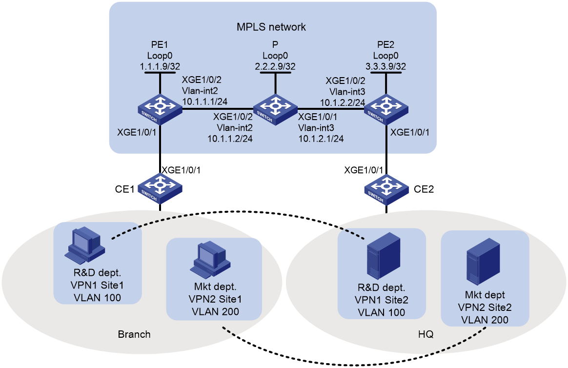
As shown Figure 4, the carrier provides L2VPN service for a user over the MPLS network. The user has R&D and marketing departments in branch offices and headquarters. They require setup of separate VPN connections between these departments by using LDP-based MPLS L2VPN to achieve data isolation.
Analysis
· LDP-based MPLS L2VPN uses a two-layer label structure, where both the inner and outer labels are dynamically generated by LDP.
· Configure a service instance and corresponding match rules on the downstream port of the PE devices to identify packets from the customer network that require transmission through an MPLS L2VPN tunnel.
Applicable hardware and software versions
Table 3 Applicable hardware and software versions
|
Hardware |
Software version |
|
S6812 series S6813 series |
Release 6628Pxx series |
|
S6550XE-HI series |
Release 8106Pxx |
|
S6525XE-HI series |
Release 8106Pxx |
|
S5850 series |
Unsupported |
|
S5570S-EI series |
Unsupported |
|
S5560X-EI series |
Release 6628Pxx |
|
S5560X-HI series |
Release 6628Pxx |
|
S5500V2-EI series |
Release 6628Pxx series |
|
MS4520V2-30F |
Release 6628Pxx series |
|
MS4520V2-30C MS4520V2-54C |
Release 6628Pxx series |
|
MS4520V2-28S MS4520V2-24TP |
Unsupported |
|
S6520X-HI series S6520X-EI series |
Release 6628Pxx series |
|
S6520X-SI series S6520-SI series |
Release 6628Pxx series |
|
S5000-EI series |
Release 6628Pxx series |
|
MS4600 series |
Release 6628Pxx series |
|
ES5500 series |
Release 6628Pxx series |
|
S5560S-EI series S5560S-SI series |
Unsupported |
|
S5500V3-24P-SI S5500V3-48P-SI |
Unsupported |
|
S5500V3-SI series (excluding the S5500V3-24P-SI and S5500V3-48P-SI) |
Unsupported |
|
S5170-EI series |
Unsupported |
|
S5130S-HI series S5130S-EI series S5130S-SI series S5130S-LI series |
Unsupported |
|
S5120V2-SI series S5120V2-LI Series |
Unsupported |
|
S5120V3-EI series |
Unsupported |
|
S5120V3-36F-SI S5120V3-28P-HPWR-SI S5120V3-54P-PWR-SI |
Unsupported |
|
S5120V3-SI series (excluding S5120V3-36F-SI, S5120V3-28P-HPWR-SI, and S5120V3-54P-PWR-SI) |
Unsupported |
|
S5120V3-LI series |
Unsupported |
|
S3600V3-EI series |
Unsupported |
|
S3600V3-SI series |
Unsupported |
|
S3100V3-EI series S3100V3-SI series |
Unsupported |
|
S5110V2 series |
Unsupported |
|
S5110V2-SI series |
Unsupported |
|
S5000V3-EI series S5000V5-EI series |
Unsupported |
|
S5000E-X series S5000X-EI series |
Unsupported |
|
E128C E152C E500C series E500D series |
Unsupported |
|
MS4320V2 series MS4320V3 series MS4300V2 series MS4320 series MS4200 series |
Unsupported |
|
WS5850-WiNet series |
Unsupported |
|
WS5820-WiNet series WS5810-WiNet series |
Unsupported |
|
WAS6000 series |
Unsupported |
|
IE4300-12P-AC & IE4300-12P-PWR IE4300-M series IE4320 series |
Unsupported |
|
S5135S-EI series |
Unsupported |
Procedure
Configuring IGP on the MPLS backbone network to enable communication between PEs and P devices in the backbone network
· Configure PE 1:
# Configure a loopback interface address.
<PE1> system-view
[PE1] interface loopback 0
[PE1-LoopBack0] ip address 1.1.1.9 32
[PE1-LoopBack0] quit
# Create VLAN 2 and add Ten-GigabitEthernet1/0/2 to VLAN 2.
[PE1] vlan 2
[PE1-vlan2] port Ten-GigabitEthernet 1/0/2
[PE1-vlan2] quit
# Create VLAN-interface 2.
[PE1] interface vlan-interface 2
[PE1-Vlan-interface2] ip address 10.1.1.1 24
[PE1-Vlan-interface2] quit
# Configure OSPF on PE 1 for establishing LSPs.
[PE1] ospf
[PE1-ospf-1] area 0
[PE1-ospf-1-area-0.0.0.0] network 10.1.1.0 0.0.0.255
[PE1-ospf-1-area-0.0.0.0] network 1.1.1.9 0.0.0.0
[PE1-ospf-1-area-0.0.0.0] quit
[PE1-ospf-1] quit
· Configure the P device:
# Configure a loopback interface address.
<P> system-view
[P] interface loopback 0
[P-LoopBack0] ip address 2.2.2.9 32
[P-LoopBack0] quit
# Create VLAN 2 and add Ten-GigabitEthernet 1/0/2 to VLAN 2.
[P] vlan 2
[P-vlan2] port Ten-GigabitEthernet1/0/2
[P-vlan2] quit
# Configure VLAN-interface 2.
[P] interface vlan-interface 2
[P-Vlan-interface2] ip address 10.1.1.2 24
[P-Vlan-interface2] quit
# Create VLAN 3 and add Ten-GigabitEthernet 1/0/1 to VLAN 3.
[P] vlan 3
[P-vlan3] port Ten-GigabitEthernet1/0/1
[P-vlan3] quit
# Configure VLAN-interface 3.
[P] interface vlan-interface 3
[P-Vlan-interface3] ip address 10.1.2.1 24
[P-Vlan-interface3] quit
# Configure OSPF on the P device for establishing LSPs.
[P] ospf
[P-ospf-1] area 0
[P-ospf-1-area-0.0.0.0] network 10.1.1.0 0.0.0.255
[P-ospf-1-area-0.0.0.0] network 10.1.2.0 0.0.0.255
[P-ospf-1-area-0.0.0.0] network 2.2.2.9 0.0.0.0
[P-ospf-1-area-0.0.0.0] quit
[P-ospf-1] quit
· Configure PE 2:
# Configure a loopback interface address.
<PE2> system-view
[PE2] interface loopback 0
[PE2-LoopBack0] ip address 3.3.3.9 32
[PE2-LoopBack0] quit
# Create VLAN 3 and add Ten-GigabitEthernet 1/0/2 to VLAN 3.
[PE2] vlan 3
[PE2-vlan3] port Ten-GigabitEthernet 1/0/2
[PE2-vlan3] quit
# Create VLAN-interface 3.
[PE2] interface vlan-interface 3
[PE2-Vlan-interface3] ip address 10.1.2.2 24
[PE2-Vlan-interface3] quit
# Configure OSPF on PE 2 for establishing LSPs.
[PE2] ospf
[PE2-ospf-1] area 0
[PE2-ospf-1-area-0.0.0.0] network 10.1.2.0 0.0.0.255
[PE2-ospf-1-area-0.0.0.0] network 3.3.3.9 0.0.0.0
[PE2-ospf-1-area-0.0.0.0] quit
[PE2-ospf-1] quit
Configuring basic MPLS capabilities and MPLS LDP on the MPLS backbone network to establish LDP LSPs
· Configure PE 1:
# Configure an LSR ID.
[PE1] mpls lsr-id 1.1.1.9
# Enable LDP globally.
[PE1] mpls ldp
[PE1-ldp] quit
# Enable MPLS and LDP VLAN-interface 2.
[PE1] interface vlan-interface 2
[PE1-Vlan-interface2] mpls enable
[PE1-Vlan-interface2] mpls ldp enable
[PE1-Vlan-interface2] quit
· Configure the P device:
# Configure an LSR ID.
[P] mpls lsr-id 2.2.2.9
# Enable LDP globally.
[P] mpls ldp
[P-ldp] quit
# Enable MPLS and LDP VLAN-interface 2.
[P] interface vlan-interface 2
[P-Vlan-interface2] mpls enable
[P-Vlan-interface2] mpls ldp enable
[P-Vlan-interface2] quit
# Enable MPLS and LDP on VLAN-interface 3.
[P] interface vlan-interface 3
[P-Vlan-interface3] mpls enable
[P-Vlan-interface3] mpls ldp enable
[P-Vlan-interface3] quit
· Configure PE 2.
# Configure an LSR ID.
[PE2] mpls lsr-id 3.3.3.9
# Enable LDP globally.
[PE2] mpls ldp
[PE2-ldp] quit
# Enable MPLS and LDP on VLAN-interface 3.
[PE2] interface vlan-interface 3
[PE2-Vlan-interface3] mpls enable
[PE2-Vlan-interface3] mpls ldp enable
[PE2-Vlan-interface3] quit
Configuring service instances for data from different departments and bind them to different MPLS L2VPNs
· Configure PE 1:
# Enable MPLS L2VPN globally.
[PE1] l2vpn enable
# Create service instance 100 on Ten-GigabitEthernet 1/0/1 to match packets from VLAN 100.
[PE1] interface ten-gigabitethernet1/0/1
[PE1-Ten-GigabitEthernet1/0/1] service-instance 100
[PE1-Ten-GigabitEthernet1/0/1-srv100] encapsulation s-vid 100
[PE1-Ten-GigabitEthernet1/0/1-srv100] quit
# Create service instance 200 on Ten-GigabitEthernet 1/0/1 to match packets from VLAN 200.
[PE1-Ten-GigabitEthernet1/0/1] service-instance 200
[PE1-Ten-GigabitEthernet1/0/1-srv200] encapsulation s-vid 200
[PE1-Ten-GigabitEthernet1/0/1-srv200] quit
[PE1-Ten-GigabitEthernet1/0/1] quit
# Create a cross-connect group named vpna and create a cross-connect named ldp. Bind service instance 100 on Ten-GigabitEthernet 1/0/1 to this cross-connect and create an LDP PW in the cross-connect to associate the AC and PW.
[PE1] xconnect-group vpna
[PE1-xcg-vpna] connection ldp
[PE1-xcg-vpna-ldp] ac interface Ten-GigabitEthernet 1/0/1 service-instance 100
[PE1-xcg-vpna-ldp] peer 3.3.3.9 pw-id 100
[PE1-xcg-vpna-ldp-3.3.3.9-100] quit
[PE1-xcg-vpna-ldp] quit
[PE1-xcg-vpna] quit
# Create a cross-connect group named vpnb and create a cross-connect named ldp. Bind service instance 200 on Ten-GigabitEthernet 1/0 1 to this cross-connect and create an LDP PW in the cross-connect to associate the AC and PW.
[PE1] xconnect-group vpnb
[PE1-xcg-vpnb] connection ldp
[PE1-xcg-vpnb-ldp] ac interface Ten-GigabitEthernet 1/0/1 service-instance 200
[PE1-xcg-vpnb-ldp] peer 3.3.3.9 pw-id 200
[PE1-xcg-vpnb-ldp-3.3.3.9-200] quit
[PE1-xcg-vpnb-ldp] quit
[PE1-xcg-vpnb] quit
· Configure PE 2:
# Enable MPLS L2VPN globally.
[PE2] l2vpn enable
# Create service instance 100 on Ten-GigabitEthernet 1/0/1 to match packets from VLAN 100.
[PE2] interface ten-gigabitethernet1/0/1
[PE2-Ten-GigabitEthernet1/0/1] service-instance 100
[PE2-Ten-GigabitEthernet1/0/1-srv100] encapsulation s-vid 100
[PE2-Ten-GigabitEthernet1/0/1-srv100] quit
# Create service instance 200 on Ten-GigabitEthernet 1/0/1 to match packets from VLAN 200.
[PE2-Ten-GigabitEthernet1/0/1] service-instance 200
[PE2-Ten-GigabitEthernet1/0/1-srv200] encapsulation s-vid 200
[PE2-Ten-GigabitEthernet1/0/1-srv200] quit
[PE2-Ten-GigabitEthernet1/0/1] quit
# Create a cross-connect group named vpna and create a cross-connect named ldp. Bind service instance 100 on Ten-GigabitEthernet 1/0/1 to this cross-connect and create an LDP PW in the cross-connect to associate the AC and PW.
[PE2] xconnect-group vpna
[PE2-xcg-vpna] connection ldp
[PE2-xcg-vpna-ldp] ac interface Ten-GigabitEthernet 1/0/1 service-instance 100
[PE2-xcg-vpna-ldp] peer 1.1.1.9 pw-id 100
[PE2-xcg-vpna-ldp-1.1.1.9-100] quit
[PE2-xcg-vpna-ldp] quit
[PE2-xcg-vpna] quit
# Create a cross-connect group named vpnb and create a cross-connect named ldp. Bind service instance 100 on Ten-GigabitEthernet 1/0 1 to this cross-connect and create an LDP PW in the cross-connect to associate the AC and PW.
[PE2] xconnect-group vpnb
[PE2-xcg-vpnb] connection ldp
[PE2-xcg-vpnb-ldp] ac interface Ten-GigabitEthernet 1/0/1 service-instance 200
[PE2-xcg-vpnb-ldp] peer 1.1.1.9 pw-id 200
[PE2-xcg-vpnb-ldp-1.1.1.9-200] quit
[PE2-xcg-vpnb-ldp] quit
[PE2-xcg-vpnb] quit
Connecting CEs to PEs
# Configure the uplink interface to the PE to allow tagged packets from the site to pass through. The following uses CE1 as an example. Configure CE2 in the same way CE1 is configured.
<CE1> system-view
[CE1] vlan 100
[CE1-vlan100] quit
[CE1] vlan 200
[CE1-vlan200] quit
[CE1] interface Ten-GigabitEthernet 1/0/1
[CE1-Ten-GigabitEthernet1/0/1] port link-type trunk
[CE1-Ten-GigabitEthernet1/0/1] port trunk permit vlan 100 200
Verifying the configuration
# Display L2VPN connection information on PE 1 to verify that two LDP PWs have been set up.
[PE1] display l2vpn pw
Flags: M - main, B - backup, H - hub link, S - spoke link, N - no split horizon
Total number of PWs: 2, 2 up, 0 blocked, 0 down, 0 defect
Xconnect-group Name: vpna
Peer PW ID In/Out Label Proto Flag Link ID State
3.3.3.9 100 65663/65663 LDP M 1 Up
Xconnect-group Name: vpnb
Peer PW ID In/Out Label Proto Flag Link ID State
3.3.3.9 200 65662/65662 LDP M 1 Up
# Verify that LDP PW information can also be displayed on PE 2.
[PE2] display l2vpn pw
Flags: M - main, B - backup, H - hub link, S - spoke link, N - no split horizon
Total number of PWs: 2, 2 up, 0 blocked, 0 down, 0 defect
Xconnect-group Name: vpna
Peer PW ID In/Out Label Proto Flag Link ID State
1.1.1.9 100 65663/65663 LDP M 1 Up
Xconnect-group Name: vpnb
Peer PW ID In/Out Label Proto Flag Link ID State
1.1.1.9 200 65662/65662 LDP M 1 Up
# Identify whether the host and server of the same user can communicate between different sites. If they can, the L2VPN has been successfully established.
Configuration files
· CE 1 and CE 2
vlan 100
#
vlan 200
#
interface Ten-GigabitEthernet1/0/1
port link-mode bridge
port link-type trunk
port trunk permit vlan 100 200
#
· PE 1
#
ospf 1
area 0.0.0.0
network 1.1.1.9 0.0.0.0
network 10.1.1.0 0.0.0.255
#
mpls lsr-id 1.1.1.9
#
vlan 2
#
mpls ldp
#
l2vpn enable
#
interface LoopBack0
ip address 1.1.1.9 255.255.255.255
#
interface Vlan-interface2
ip address 10.1.1.1 255.255.255.0
mpls enable
mpls ldp enable
#
interface Ten-GigabitEthernet1/0/1
port link-mode bridge
service-instance 100
encapsulation s-vid 100
service-instance 200
encapsulation s-vid 200
#
interface Ten-GigabitEthernet1/0/2
port link-mode bridge
port access vlan 2
#
xconnect-group vpna
connection ldp
ac interface Ten-GigabitEthernet1/0/1 service-instance 100
peer 3.3.3.9 pw-id 100
#
xconnect-group vpnb
connection ldp
ac interface Ten-GigabitEthernet1/0/1 service-instance 200
peer 3.3.3.9 pw-id 200
#
· P
#
ospf 1
area 0.0.0.0
network 10.1.1.0 0.0.0.255
network 10.1.2.0 0.0.0.255
network 2.2.2.9 0.0.0.0
#
mpls lsr-id 2.2.2.9
#
vlan 2
#
vlan 3
#
mpls ldp
#
interface LoopBack0
ip address 2.2.2.9 255.255.255.255
#
interface Vlan-interface2
ip address 10.1.1.2 255.255.255.0
mpls enable
mpls ldp enable
#
interface Vlan-interface3
ip address 10.1.2.1 255.255.255.0
mpls enable
mpls ldp enable
#
interface Ten-GigabitEthernet1/0/1
port link-mode bridge
port access vlan 3
#
interface Ten-GigabitEthernet1/0/2
port link-mode bridge
port access vlan 2
#
· PE 2
#
ospf 1
area 0.0.0.0
network 10.1.2.0 0.0.0.255
network 3.3.3.9 0.0.0.0
#
mpls lsr-id 3.3.3.9
#
vlan 3
#
mpls ldp
#
l2vpn enable
#
interface LoopBack0
ip address 3.3.3.9 255.255.255.255
#
interface Vlan-interface3
ip address 10.1.2.2 255.255.255.0
mpls enable
mpls ldp enable
#
interface Ten-GigabitEthernet1/0/1
port link-mode bridge
service-instance 100
encapsulation s-vid 100
service-instance 200
encapsulation s-vid 200
#
interface Ten-GigabitEthernet1/0/2
port link-mode bridge
port access vlan 3
#
xconnect-group vpna
connection ldp
ac interface Ten-GigabitEthernet1/0/1 service-instance 100
peer 1.1.1.9 pw-id 100
#
xconnect-group vpnb
connection ldp
ac interface Ten-GigabitEthernet1/0/1 service-instance 200
peer 1.1.1.9 pw-id 200
#
Example: Configuring BGP-based MPLS L2VPN
Network configuration
As shown in Figure 5, the MPLS network provides MPLS L2VPN services to the user. The user has two sites deployed and the number might be expanded to 10. To connect the two sites over VPN and reserve VPN resources for the remaining 8 sites, configure BGP-based MPLS L2VPN.
Analysis
· BGP-based MPLS L2VPN uses a two-layer label structure, where the inner label is generated by BGP and the outer label is dynamically created using LDP.
· To enable PEs to use BGP for exchanging private network labels, create service instances and IBGP connections on each PE and configure them as BGP peers.
· To reduce the configuration workload when you increase the number of sites to 10, set the label block size to 10.
Applicable hardware and software versions
Table 4 Applicable hardware and software versions
|
Hardware |
Software version |
|
S6812 series S6813 series |
Release 6628Pxx series |
|
S6550XE-HI series |
Release 8106Pxx |
|
S6525XE-HI series |
Release 8106Pxx |
|
S5850 series |
Unsupported |
|
S5570S-EI series |
Unsupported |
|
S5560X-EI series |
Release 6628Pxx |
|
S5560X-HI series |
Release 6628Pxx |
|
S5500V2-EI series |
Release 6628Pxx series |
|
MS4520V2-30F |
Release 6628Pxx series |
|
MS4520V2-30C MS4520V2-54C |
Release 6628Pxx series |
|
MS4520V2-28S MS4520V2-24TP |
Unsupported |
|
S6520X-HI series S6520X-EI series |
Release 6628Pxx series |
|
S6520X-SI series S6520-SI series |
Release 6628Pxx series |
|
S5000-EI series |
Release 6628Pxx series |
|
MS4600 series |
Release 6628Pxx series |
|
ES5500 series |
Release 6628Pxx series |
|
S5560S-EI series S5560S-SI series |
Unsupported |
|
S5500V3-24P-SI S5500V3-48P-SI |
Unsupported |
|
S5500V3-SI series (excluding the S5500V3-24P-SI and S5500V3-48P-SI) |
Unsupported |
|
S5170-EI series |
Unsupported |
|
S5130S-HI series S5130S-EI series S5130S-SI series S5130S-LI series |
Unsupported |
|
S5120V2-SI series S5120V2-LI Series |
Unsupported |
|
S5120V3-EI series |
Unsupported |
|
S5120V3-36F-SI S5120V3-28P-HPWR-SI S5120V3-54P-PWR-SI |
Unsupported |
|
S5120V3-SI series (excluding S5120V3-36F-SI, S5120V3-28P-HPWR-SI, and S5120V3-54P-PWR-SI) |
Unsupported |
|
S5120V3-LI series |
Unsupported |
|
S3600V3-EI series |
Unsupported |
|
S3600V3-SI series |
Unsupported |
|
S3100V3-EI series S3100V3-SI series |
Unsupported |
|
S5110V2 series |
Unsupported |
|
S5110V2-SI series |
Unsupported |
|
S5000V3-EI series S5000V5-EI series |
Unsupported |
|
S5000E-X series S5000X-EI series |
Unsupported |
|
E128C E152C E500C series E500D series |
Unsupported |
|
MS4320V2 series MS4320V3 series MS4300V2 series MS4320 series MS4200 series |
Unsupported |
|
WS5850-WiNet series |
Unsupported |
|
WS5820-WiNet series WS5810-WiNet series |
Unsupported |
|
WAS6000 series |
Unsupported |
|
IE4300-12P-AC & IE4300-12P-PWR IE4300-M series IE4320 series |
Unsupported |
|
S5135S-EI series |
Unsupported |
Procedure
Configuring IGP on the MPLS backbone network to enable communication between PEs and P devices on the backbone network
· Configure PE 1:
# Configure a loopback interface address.
<PE1> system-view
[PE1] interface loopback 0
[PE1-LoopBack0] ip address 1.1.1.9 32
[PE1-LoopBack0] quit
# Create VLAN 2 and add Ten-GigabitEthernet 1/0/2 to VLAN 2.
[PE1] vlan 2
[PE1-vlan2] port Ten-GigabitEthernet 1/0/2
[PE1-vlan2] quit
# Create VLAN-interface 2.
[PE1] interface vlan-interface 2
[PE1-Vlan-interface2] ip address 10.1.1.1 24
[PE1-Vlan-interface2] quit
# Configure OSPF on PE 1 for establishing LSPs.
[PE1] ospf
[PE1-ospf-1] area 0
[PE1-ospf-1-area-0.0.0.0] network 10.1.1.0 0.0.0.255
[PE1-ospf-1-area-0.0.0.0] network 1.1.1.9 0.0.0.0
[PE1-ospf-1-area-0.0.0.0] quit
[PE1-ospf-1] quit
· Configure the P device:
# Configure a loopback interface address.
<P> system-view
[P] interface loopback 0
[P-LoopBack0] ip address 2.2.2.9 32
[P-LoopBack0] quit
# Create VLAN 2 and add Ten-GigabitEthernet 1/0/2 to VLAN 2.
[P] vlan2
[P-vlan2] port Ten-GigabitEthernet1/0/2
[P-vlan2] quit
# Configure VLAN-interface 2.
[P] interface vlan-interface 2
[P-Vlan-interface2] ip address 10.1.1.2 24
[P-Vlan-interface2] quit
# Create VLAN 3 and add Ten-GigabitEthernet 1/0/1 to VLAN 3.
[P] vlan3
[P-vlan3] port Ten-GigabitEthernet1/0/1
[P-vlan3] quit
# Configure VLAN-interface 3.
[P] interface vlan-interface 3
[P-Vlan-interface3] ip address 10.1.2.1 24
[P-Vlan-interface3] quit
# Configure OSPF on the P device for establishing LSPs.
[P] ospf
[P-ospf-1] area 0
[P-ospf-1-area-0.0.0.0] network 10.1.1.0 0.0.0.255
[P-ospf-1-area-0.0.0.0] network 10.1.2.0 0.0.0.255
[P-ospf-1-area-0.0.0.0] network 2.2.2.9 0.0.0.0
[P-ospf-1-area-0.0.0.0] quit
[P-ospf-1] quit
· Configure PE 2:
# Configure a loopback interface address.
<PE2> system-view
[PE2] interface loopback 0
[PE2-LoopBack0] ip address 3.3.3.9 32
[PE2-LoopBack0] quit
# Create VLAN 3 and add Ten-GigabitEthernet 1/0/2 to VLAN 3.
[PE2] vlan 3
[PE2-vlan3] port Ten-GigabitEthernet 1/0/2
[PE2-vlan3] quit
# Create VLAN-interface 3.
[PE2] interface vlan-interface 3
[PE2-Vlan-interface3] ip address 10.1.2.2 24
[PE2-Vlan-interface3] quit
# Configure OSPF on PE 2 for establishing LSPs.
[PE2] ospf
[PE2-ospf-1] area 0
[PE2-ospf-1-area-0.0.0.0] network 10.1.2.0 0.0.0.255
[PE2-ospf-1-area-0.0.0.0] network 3.3.3.9 0.0.0.0
[PE2-ospf-1-area-0.0.0.0] quit
[PE2-ospf-1] quit
Configuring basic MPLS capabilities and MPLS LDP on the MPLS backbone network to establish LDP LSPs
· Configure PE 1:
# Configure an LSR ID.
[PE1] mpls lsr-id 1.1.1.9
# Enable MPLS L2VPN and LDP globally.
[PE1] l2vpn enable
[PE1] mpls ldp
[PE1-ldp] quit
# Enable MPLS and LDP VLAN-interface 2.
[PE1] interface vlan-interface 2
[PE1-Vlan-interface2] mpls enable
[PE1-Vlan-interface2] mpls ldp enable
[PE1-Vlan-interface2] quit
· Configure the P device:
[P] mpls lsr-id 2.2.2.9
# Enable LDP globally.
[P] mpls ldp
[P-ldp] quit
# Enable MPLS and LDP VLAN-interface 2.
[P] interface vlan-interface 2
[P-Vlan-interface2] mpls enable
[P-Vlan-interface2] mpls ldp enable
[P-Vlan-interface2] quit
# Enable MPLS and LDP on VLAN-interface 3.
[P] interface vlan-interface 3
[P-Vlan-interface3] mpls enable
[P-Vlan-interface3] mpls ldp enable
[P-Vlan-interface3] quit
· Configure PE 2:
# Configure an LSR ID.
[PE2] mpls lsr-id 3.3.3.9
# Enable MPLS L2VPN and LDP globally.
[PE2] l2vpn enable
[PE2] mpls ldp
[PE2-ldp] quit
# Enable MPLS and LDP on VLAN-interface 3.
[PE2] interface vlan-interface 3
[PE2-Vlan-interface3] mpls enable
[PE2-Vlan-interface3] mpls ldp enable
[PE2-Vlan-interface3] quit
Establishing an IBGP connection between PEs and configuring BGP PWs
· Configure PE 1:
# Create an IBGP connection to PE 2.
[PE1] bgp 100
[PE1-bgp] peer 3.3.3.9 as-number 100
[PE1-bgp] peer 3.3.3.9 connect-interface loopback 0
# Enable BGP to advertise L2VPN information to PE 2.
[PE1-bgp] address-family l2vpn
[PE1-bgp-l2vpn] peer 3.3.3.9 enable
[PE1-bgp-l2vpn] quit
[PE1-bgp] quit
# Create service instance 100 on Ten-GigabitEthernet 1/0/1 to match packets with VLAN tag 100.
[PE1] interface ten-gigabitethernet1/0/1
[PE1-Ten-GigabitEthernet1/0/1] service-instance 100
[PE1-Ten-GigabitEthernet1/0/1-srv100] encapsulation s-vid 100
[PE1-Ten-GigabitEthernet1/0/1-srv100] quit
[PE1-Ten-GigabitEthernet1/0/1] quit
# Create a cross-connect group named vpna, create local site site 1, and create a BGP PW from site 1 to remote site site 2. Bind service instance 100 on Ten-GigabitEthernet 1/0/1 to the PW.
[PE1] xconnect-group vpna
[PE1-xcg-vpna] auto-discovery bgp
[PE1-xcg-vpna-auto] route-distinguisher 2:2
[PE1-xcg-vpna-auto] vpn-target 2:2 export-extcommunity
[PE1-xcg-vpna-auto] vpn-target 2:2 import-extcommunity
[PE1-xcg-vpna-auto] site 1 range 10 default-offset 0
[PE1-xcg-vpna-auto-1] connection remote-site-id 2
[PE1-xcg-vpna-auto-1-2] ac interface Ten-GigabitEthernet 1/0/1 service-instance 100
[PE1-xcg-vpna-auto-1-2] return
· Configure PE 2:
# Create an IBGP connection to PE 1, and enable BGP to advertise L2VPN information to PE 1.
[PE2] bgp 100
[PE2-bgp] peer 1.1.1.9 as-number 100
[PE2-bgp] peer 1.1.1.9 connect-interface loopback 0
[PE2-bgp] address-family l2vpn
[PE2-bgp-l2vpn] peer 1.1.1.9 enable
[PE2-bgp-l2vpn] quit
[PE2-bgp] quit
# Create service instance 100 on Ten-GigabitEthernet 1/0/1 to match packets with VLAN tag 100.
[PE2] interface ten-gigabitethernet1/0/1
[PE2-Ten-GigabitEthernet1/0/1] service-instance 100
[PE2-Ten-GigabitEthernet1/0/1-srv100] encapsulation s-vid 100
[PE2-Ten-GigabitEthernet1/0/1-srv100] quit
[PE2-Ten-GigabitEthernet1/0/1] quit
# Create a cross-connect group named vpna, create local site site 2, and create a BGP PW from site 2 to remote site site 1.Bind service instance 100 on Ten-GigabitEthernet 1/0/1 to the PW.
[PE2] xconnect-group vpna
[PE2-xcg-vpna] auto-discovery bgp
[PE2-xcg-vpna-auto] route-distinguisher 2:2
[PE2-xcg-vpna-auto] vpn-target 2:2 export-extcommunity
[PE2-xcg-vpna-auto] vpn-target 2:2 import-extcommunity
[PE2-xcg-vpna-auto] site 2 range 10 default-offset 0
[PE2-xcg-vpna-auto-2] connection remote-site-id 1
[PE2-xcg-vpna-auto-2-1] ac interface Ten-GigabitEthernet 1/0/1 service-instance 100
[PE2-xcg-vpna-auto-2-1] return
Connecting CEs to PEs
# Configure the uplink interface to the PE to allow tagged packets from the local site to pass through. The following uses CE1 as an example. Configure other CEs in the same way CE1 is configured.
<CE1> system-view
[CE1] vlan 100
[CE1-vlan100] quit
[CE1] interface Ten-GigabitEthernet 1/0/1
[CE1-Ten-GigabitEthernet1/0/1] port link-type trunk
[CE1-Ten-GigabitEthernet1/0/1] port trunk permit vlan 100
Verifying the configuration
# Display PW information on PE1 to verify that a BGP PW has been set up.
<PE1> display l2vpn pw
Flags: M - main, B - backup, H - hub link, S - spoke link, N - no split horizon
Total number of PWs: 1, 1 up, 0 blocked, 0 down, 0 defect
Xconnect-group Name: vpna
Peer PW ID/Rmt Site In/Out Label Proto Flag Link ID State
3.3.3.9 2 65538/65537 BGP M 1 Up
# Verify that PW information can also be displayed on PE 2.
<PE2> display l2vpn pw
Flags: M - main, B - backup, H - hub link, S - spoke link, N - no split horizon
Total number of PWs: 1, 1 up, 0 blocked, 0 down, 0 defect
Xconnect-group Name: vpna
Peer PW ID/Rmt Site In/Out Label Proto Flag Link ID State
1.1.1.9 1 65537/65538 BGP M 1 Up
# Use ping to identify whether hosts within the two sites can reach each other. If the ping operation succeeds, the VPN is created successfully.
Configuration files
· CE 1 and CE 2
#
vlan 100
#
interface Ten-GigabitEthernet1/0/1
port link-type trunk
port trunk permit vlan 1 100
#
· PE 1
#
ospf 1
area 0.0.0.0
network 1.1.1.9 0.0.0.0
network 10.1.1.0 0.0.0.255
#
mpls lsr-id 1.1.1.9
#
vlan 2
#
mpls ldp
#
l2vpn enable
#
interface LoopBack0
ip address 1.1.1.9 255.255.255.255
#
interface Vlan-interface2
ip address 10.1.1.1 255.255.255.0
mpls enable
mpls ldp enable
#
interface Ten-GigabitEthernet1/0/1
port link-mode bridge
service-instance 100
encapsulation s-vid 100
#
interface Ten-GigabitEthernet1/0/2
port link-mode bridge
port access vlan 2
#
bgp 100
peer 3.3.3.9 as-number 100
peer 3.3.3.9 connect-interface LoopBack0
#
address-family l2vpn
peer 3.3.3.9 enable
#
xconnect-group vpna
auto-discovery bgp
route-distinguisher 2:2
vpn-target 2:2 export-extcommunity
vpn-target 2:2 import-extcommunity
site 1 range 10 default-offset 0
connection remote-site-id 2
ac interface Ten-GigabitEthernet1/0/1 service-instance 100
#
· P
#
ospf 1
area 0.0.0.0
network 10.1.1.0 0.0.0.255
network 10.1.2.0 0.0.0.255
network 2.2.2.9 0.0.0.0
#
mpls lsr-id 2.2.2.9
#
vlan 2
#
vlan 3
#
mpls ldp
#
interface LoopBack0
ip address 2.2.2.9 255.255.255.255
#
interface Vlan-interface2
ip address 10.1.1.2 255.255.255.0
mpls enable
mpls ldp enable
#
interface Vlan-interface3
ip address 10.1.2.1 255.255.255.0
mpls enable
mpls ldp enable
#
interface Ten-GigabitEthernet1/0/1
port link-mode bridge
port access vlan 3
#
interface Ten-GigabitEthernet1/0/2
port link-mode bridge
port access vlan 2
#
· PE 2
#
ospf 1
area 0.0.0.0
network 10.1.2.0 0.0.0.255
network 3.3.3.9 0.0.0.0
#
mpls lsr-id 3.3.3.9
#
vlan 3
#
mpls ldp
#
l2vpn enable
#
interface LoopBack0
ip address 3.3.3.9 255.255.255.255
#
interface Vlan-interface3
ip address 10.1.2.2 255.255.255.0
mpls enable
mpls ldp enable
#
interface Ten-GigabitEthernet1/0/1
port link-mode bridge
service-instance 100
encapsulation s-vid 100
#
interface Ten-GigabitEthernet1/0/2
port link-mode bridge
port access vlan 3
#
bgp 100
peer 1.1.1.9 as-number 100
peer 1.1.1.9 connect-interface LoopBack0
#
address-family l2vpn
peer 1.1.1.9 enable
#
xconnect-group vpna
auto-discovery bgp
route-distinguisher 2:2
vpn-target 2:2 export-extcommunity
vpn-target 2:2 import-extcommunity
site 2 range 10 default-offset 0
connection remote-site-id 1
ac interface Ten-GigabitEthernet1/0/1 service-instance 100
#