- Table of Contents
-
- H3C Fixed Port Campus Switches Configuration Examples-6W104
- 00-Applicable hardware and software versions
- 01-Login Management Configuration Examples
- 02-RBAC Configuration Examples
- 03-Software Upgrade Examples
- 04-ISSU Configuration Examples
- 05-Software Patching Examples
- 06-Ethernet Link Aggregation Configuration Examples
- 07-Port Isolation Configuration Examples
- 08-Spanning Tree Configuration Examples
- 09-VLAN Configuration Examples
- 10-VLAN Tagging Configuration Examples
- 11-DHCP Snooping Configuration Examples
- 12-Cross-Subnet Dynamic IP Address Allocation Configuration Examples
- 13-IPv6 over IPv4 Tunneling with OSPFv3 Configuration Examples
- 14-IPv6 over IPv4 GRE Tunnel Configuration Examples
- 15-GRE with OSPF Configuration Examples
- 16-OSPF Configuration Examples
- 17-IS-IS Configuration Examples
- 18-BGP Configuration Examples
- 19-Policy-Based Routing Configuration Examples
- 20-OSPFv3 Configuration Examples
- 21-IPv6 IS-IS Configuration Examples
- 22-Routing Policy Configuration Examples
- 23-IGMP Snooping Configuration Examples
- 24-IGMP Configuration Examples
- 25-MLD Snooping Configuration Examples
- 26-IPv6 Multicast VLAN Configuration Examples
- 27-ACL Configuration Examples
- 28-Traffic Policing Configuration Examples
- 29-GTS and Rate Limiting Configuration Examples
- 30-Traffic Filtering Configuration Examples
- 31-AAA Configuration Examples
- 32-Port Security Configuration Examples
- 33-Portal Configuration Examples
- 34-SSH Configuration Examples
- 35-IP Source Guard Configuration Examples
- 36-Ethernet OAM Configuration Examples
- 37-CFD Configuration Examples
- 38-DLDP Configuration Examples
- 39-VRRP Configuration Examples
- 40-BFD Configuration Examples
- 41-NTP Configuration Examples
- 42-SNMP Configuration Examples
- 43-NQA Configuration Examples
- 44-Mirroring Configuration Examples
- 45-sFlow Configuration Examples
- 46-OpenFlow Configuration Examples
- 47-MAC Address Table Configuration Examples
- 48-Static Multicast MAC Address Entry Configuration Examples
- 49-IP Unnumbered Configuration Examples
- 50-MVRP Configuration Examples
- 51-MCE Configuration Examples
- 52-Attack Protection Configuration Examples
- 53-Smart Link Configuration Examples
- 54-RRPP Configuration Examples
- 55-BGP Route Selection Configuration Examples
- 56-IS-IS Route Summarization Configuration Examples
- 57-VXLAN Configuration Examples
- 58-DRNI Configuration Examples
- 59-IRF 3.1 Configuration Examples
- 60-PTP Configuration Examples
- 61-S-MLAG Configuration Examples
- 62-Puppet Configuration Examples
- 63-802.1X Configuration Examples
- 64-MAC Authentication Configuration Examples
- 65-ISATAP Tunnel and 6to4 Tunnel Configuration Examples
- 66-BIDIR-PIM Configuration Examples
- 67-Congestion Avoidance and Queue Scheduling Configuration Examples
- 68-Basic MPLS Configuration Examples
- 69-MPLS L3VPN Configuration Examples
- 70-MPLS OAM Configuration Examples
- 71-EVPN-DCI over an MPLS L3VPN Network Configuration Examples
- 72-DRNI and EVPN Configuration Examples
- 73-Multicast VPN Configuration Examples
- 74-MPLS TE Configuration Examples
- 75-Control Plane-Based QoS Policy Configuration Examples
- 76-Priority Mapping and Queue Scheduling Configuration Examples
- 77-ARP Attack Protection Configuration Examples
- 78-IRF Software Upgrade Configuration Examples
- 79-IRF Member Replacement Configuration Examples
- 80-Layer 3 Multicast on Multicast Source-Side DR System Configuration Examples
- 81-EVPN Multicast Configuration Examples
- Related Documents
-
| Title | Size | Download |
|---|---|---|
| 80-Layer 3 Multicast on Multicast Source-Side DR System Configuration Examples | 157.30 KB |
Example: Configuring Layer 3 IPv4 multicast on a DR system attached to multicast sources
Applicable hardware and software versions
Assigning IP addresses and configuring unicast routing
Example: Configuring Layer 3 IPv6 multicast on a DR system attached to multicast sources
Applicable hardware and software versions
Assigning IPv6 addresses and configuring unicast routing
Introduction
This document provides examples for configuring Layer 3 multicast on a DR system attached to multicast sources.
Distributed Resilient Network Interconnect (DRNI) virtualizes two physical devices into one system through multichassis link aggregation. You can configure PIM on a DR system attached to multicast receivers or multicast sources to prevent single points of failure from interrupting multicast forwarding.
Prerequisites
The configuration examples in this document were created and verified in a lab environment, and all the devices were started with the factory default configuration. When you are working on a live network, make sure you understand the potential impact of every command on your network.
This document assumes that you have basic knowledge of DRNI and Layer 3 multicast.
Example: Configuring Layer 3 IPv4 multicast on a DR system attached to multicast sources
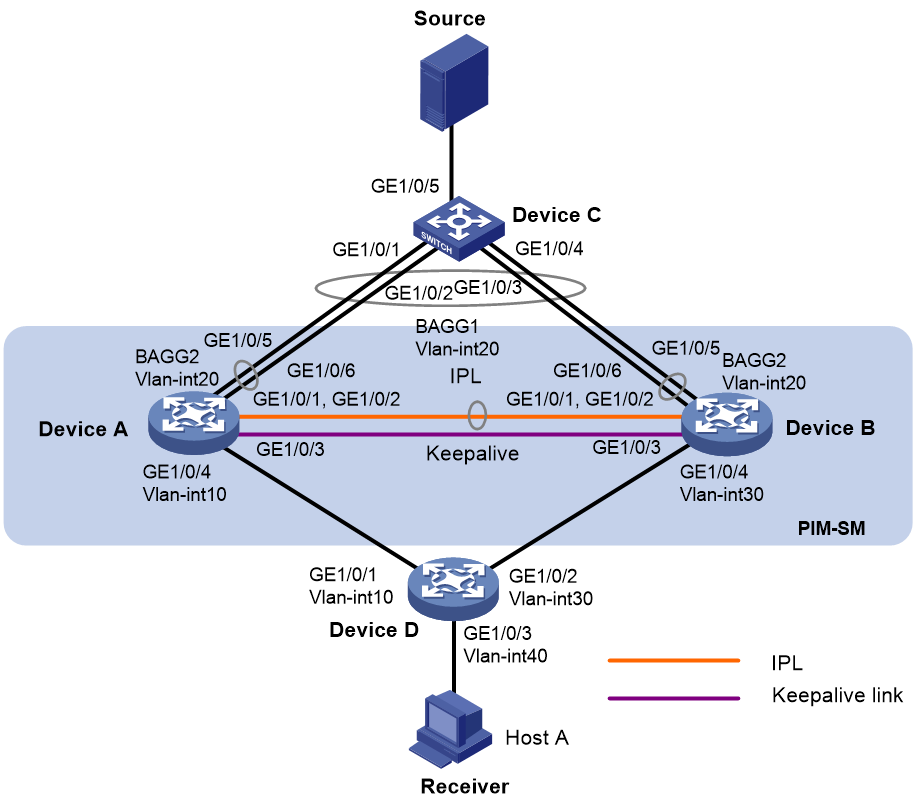
Network configuration
As shown in Figure 1:
· OSPF runs on the network.
· VOD streams are sent to receiver hosts in multicast. The receivers of different subnets form stub networks, and a minimum of one receiver host exist on each stub network.
· The entire PIM-SM domain contains only one BSR.
· Device C is a Layer 2 device attached to the multicast source. Switch A and Switch B are virtualized into a DR system, which is connected to Switch C through a multichassis aggregate link. VLAN-interface 20 interfaces on the DR system are the gateway for the multicast source.
· Host A is a multicast data receiver attached to Device D.
· The GigabitEthernet 1/0/3 interfaces on Device A and Device B are excluded from the shutdown action by DRNI MAD to set up the keepalive link.
· A VRRP group is configured on VLAN-interface 20 interfaces. In the VRRP group, Device A is the master.
· DR interfaces on Switch A and Switch B permit packets from VLAN 20 to pass through. PIM is enabled on VLAN-interface 20 of Switch A and Switch B.
· IP multicast routing is enabled on Switch A and Switch B.
|
Device |
Interface |
IP address |
Device |
Interface |
IP address |
|
Device A |
Vlan-int20 |
20.0.0.1/24 |
Device D |
Vlan-int10 |
100.0.0.2/24 |
|
|
GE1/0/3 |
200.0.0.1/24 |
|
Vlan-int30 |
30.0.0.2/24 |
|
|
Vlan-int10 |
100.0.0.1/24 |
|
Vlan-int40 |
40.0.0.2/24 |
|
|
Loop0 |
1.1.1.1 |
|
|
|
|
Device B |
Vlan-int20 |
20.0.0.2/24 |
|
|
|
|
|
GE1/0/3 |
200.0.0.2/24 |
|
|
|
|
|
Vlan-int30 |
30.0.0.1/24 |
|
|
|
|
|
Loop0 |
2.2.2.2 |
|
|
|
Applicable hardware and software versions
The following matrix shows the hardware and software versions to which this configuration example is applicable:
|
Hardware |
Software version |
|
S6812 switch series S6813 switch series |
Release 6615Pxx, Release 6628Pxx |
|
S6550XE-HI switch series |
Release 6008 or later |
|
S6525XE-HI switch series |
Release 6008 or later |
|
S5850 switch series |
Not supported |
|
S5570S-EI switch series |
Not supported |
|
S5560X-EI switch series |
Release 6615Pxx, Release 6628Pxx |
|
S5560X-HI switch series |
Release 6615Pxx, Release 6628Pxx |
|
S5500V2-EI switch series |
Release 6615Pxx, Release 6628Pxx |
|
MS4520V2-30F switch |
Release 6615Pxx, Release 6628Pxx |
|
MS4520V2-30C switch MS4520V2-54C switch |
Release 6615Pxx, Release 6628Pxx |
|
MS4520V2-28S switch MS4520V2-24TP switch |
Not supported |
|
S6520X-HI switch series S6520X-EI switch series |
Release 6615Pxx, Release 6628Pxx |
|
S6520X-SI switch series S6520-SI switch series |
Release 6615Pxx, Release 6628Pxx |
|
S5000-EI switch series |
Release 6615Pxx, Release 6628Pxx |
|
MS4600 switch series |
Release 6615Pxx, Release 6628Pxx |
|
ES5500 switch series |
Release 6615Pxx, Release 6628Pxx |
|
S5560S-EI switch series S5560S-SI switch series |
Not supported |
|
S5500V3-24P-SI switch S5500V3-48P-SI switch |
Not supported |
|
S5500V3-SI switch series (except S5500V3-24P-SI and S5500V3-48P-SI) |
Not supported |
|
S5170-EI switch series |
Not supported |
|
S5130S-HI switch series S5130S-EI switch series S5130S-SI switch series S5130S-LI switch series |
Not supported |
|
S5120V2-SI switch series S5120V2-LI switch series |
Not supported |
|
S5120V3-EI switch series |
Not supported |
|
S5120V3-36F-SI switch S5120V3-28P-HPWR-SI switch S5120V3-54P-PWR-SI switch |
Not supported |
|
S5120V3-SI switch series (except S5120V3-36F-SI, S5120V3-28P-HPWR-SI, and S5120V3-54P-PWR-SI) |
Not supported |
|
S5120V3-LI switch series |
Not supported |
|
S3600V3-EI switch series |
Not supported |
|
S3600V3-SI switch series |
Not supported |
|
S3100V3-EI switch series S3100V3-SI switch series |
Not supported |
|
S5110V2 switch series |
Not supported |
|
S5110V2-SI switch series |
Not supported |
|
S5000V3-EI switch series S5000V5-EI switch series |
Not supported |
|
S5000E-X switch series S5000X-EI switch series |
Not supported |
|
E128C switch E152C switch E500C switch series E500D switch series |
Not supported |
|
MS4320V2 switch series MS4320V3 switch series MS4300V2 switch series MS4320 switch series MS4200 switch series |
Not supported |
|
WS5850-WiNet switch series |
Not supported |
|
WS5820-WiNet switch series WS5810-WiNet switch series |
Not supported |
|
WAS6000 switch series |
Not supported |
|
IE4300-12P-AC switch IE4300-12P-PWR switch IE4300-M switch series IE4320 switch series |
Not supported |
Procedures
Assigning IP addresses and configuring unicast routing
Assign an IP address and subnet mask to each interface as shown in Figure 1, and configure OSPF on the switches in the PIM-SM domain. (Details not shown.)
Configuring Device A
# Configure the DR system settings.
<DeviceA> system-view
[DeviceA] drni system-mac 1-1-1
[DeviceA] drni system-number 1
[DeviceA] drni system-priority 123
# Configure DR keepalive packet parameters.
[DeviceA] drni keepalive ip destination 200.0.0.2 source 200.0.0.1
# Exclude the interface used for DR keepalive detection (GigabitEthernet 1/0/3) from the shutdown action by DRNI MAD.
[DeviceA] drni mad exclude interface gigabitethernet 1/0/3
# Create Layer 2 dynamic aggregate interface Bridge-Aggregation 1.
[DeviceA] interface bridge-aggregation 1
[DeviceA-Bridge-Aggregation1] link-aggregation mode dynamic
[DeviceA-Bridge-Aggregation1] quit
# Assign GigabitEthernet 1/0/1 and GigabitEthernet 1/0/2 to aggregation group 1.
[DeviceA] interface gigabitethernet 1/0/1
[DeviceA-GigabitEthernet1/0/1] port link-aggregation group 1
[DeviceA-GigabitEthernet1/0/1] quit
[DeviceA] interface gigabitethernet 1/0/2
[DeviceA-GigabitEthernet1/0/2] port link-aggregation group 1
[DeviceA-GigabitEthernet1/0/2] quit
# Create Layer 2 dynamic aggregate interface Bridge-Aggregation 2.
[DeviceA] interface bridge-aggregation 2
[DeviceA-Bridge-Aggregation2] link-aggregation mode dynamic
[DeviceA-Bridge-Aggregation2] quit
# Assign GigabitEthernet 1/0/5 and GigabitEthernet 1/0/6 to aggregation group 1.
[DeviceA] interface gigabitethernet 1/0/5
[DeviceA-GigabitEthernet1/0/5] port link-aggregation group 2
[DeviceA-GigabitEthernet1/0/5] quit
[DeviceA] interface gigabitethernet 1/0/6
[DeviceA-GigabitEthernet1/0/6] port link-aggregation group 2
[DeviceA-GigabitEthernet1/0/6] quit
# Configure Bridge-Aggregation 1 as a trunk port, assign it to all VLANs, and specify it as the IPP.
[DeviceA] interface bridge-aggregation 1
[DeviceA-Bridge-Aggregation1] port link-type trunk
[DeviceA-Bridge-Aggregation1] port trunk permit vlan all
[DeviceA-Bridge-Aggregation1] port drni intra-portal-port 1
[DeviceA-Bridge-Aggregation1] quit
# Configure Bridge-Aggregation 2 as a trunk port, and assign it to VLAN 20 and a DR group.
[DeviceA] interface bridge-aggregation 2
[DeviceA-Bridge-Aggregation2] port link-type trunk
[DeviceA-Bridge-Aggregation2] port trunk permit vlan 20
[DeviceA-Bridge-Aggregation2] port drni group 1
[DeviceA-Bridge-Aggregation2] quit
# Configure VRRP group 1 on VLAN-interface 20, and set the priority of Device A to 200 for it to be the master in the VRRP group.
[DeviceA] vlan 20
[DeviceA-vlan20] quit
[DeviceA] interface vlan-interface 20
[DeviceA-Vlan-interface20] vrrp vrid 1 virtual-ip 20.0.0.10
[DeviceA-Vlan-interface20] vrrp vrid 1 priority 200
[DeviceA-Vlan-interface20] quit
# Enable IP multicast routing, enable IGMP and PIM on VLAN-interface 10, and enable PIM-SM on other interfaces as required.
[DeviceA] multicast routing
[DeviceA-mrib] quit
[DeviceA] interface vlan-interface 10
[DeviceA-Vlan-interface10] igmp enable
[DeviceA-Vlan-interface10] pim sm
[DeviceA-Vlan-interface10] quit
[DeviceA] interface vlan-interface 20
[DeviceA-Vlan-interface20] pim sm
[DeviceA-Vlan-interface20] quit
[DeviceA] interface loopback 0
[DeviceA-LoopBack0] pim sm
[DeviceA-LoopBack0] quit
# Specify the IP address of Loopback 0 as a C-RP and a C-BSR.
[DeviceA] pim
[DeviceA-pim] c-rp 1.1.1.1
[DeviceA-pim] c-bsr 1.1.1.1
[DeviceA-pim] quit
Configuring Device B
Configure Device B in the same way you configure Device A. (Details not shown.)
Configuring Device C
# Create Layer 2 dynamic aggregate interface Bridge-Aggregation 1.
<DeviceC> system-view
[DeviceC] interface bridge-aggregation 1
[DeviceC-Bridge-Aggregation1] link-aggregation mode dynamic
[DeviceC-Bridge-Aggregation1] quit
# Assign GigabitEthernet 1/0/1 through GigabitEthernet 1/0/4 to aggregation group 1.
[DeviceC] interface range gigabitethernet 1/0/1 to gigabitethernet 1/0/4
[DeviceC-if-range] port link-aggregation group 1
[DeviceC-if-range] quit
# Configure Bridge-Aggregation 2 as a trunk port, and assign it to VLAN 20.
[DeviceC] interface bridge-aggregation 1
[DeviceC-Bridge-Aggregation1] port link-type trunk
[DeviceC-Bridge-Aggregation1] port trunk permit vlan 20
[DeviceC-Bridge-Aggregation1] quit
# Assign GigabitEthernet 1/0/5 to VLAN 20.
[DeviceC] interface gigabitethernet 1/0/5
[DeviceC-GigabitEthernet1/0/5] port access vlan 20
[DeviceC-GigabitEthernet1/0/5] quit
Configuring Device D
# Assign GigabitEthernet 1/0/1, GigabitEthernet 1/0/2, and GigabitEthernet 1/0/3 to VLAN 10, VLAN 30, and VLAN 40, respectively.
<DeviceD> system-view
[DeviceD] vlan 10
[DeviceD-vlan10] quit
[DeviceD] interface gigabitethernet1/0/1
[DeviceD-GigabitEthernet1/0/1] port access vlan 10
[DeviceD-GigabitEthernet1/0/1] quit
[DeviceD] vlan 40
[DeviceD-vlan40] quit
[DeviceD] interface gigabitethernet1/0/3
[DeviceD-GigabitEthernet1/0/3] port access vlan 40
[DeviceD] vlan 30
[DeviceD-vlan30] quit
[DeviceD] interface gigabitethernet1/0/2
[DeviceD-GigabitEthernet1/0/2] port access vlan 30
# Enable IP multicast routing, and enable PIM-SM on VLAN-interface 10 and VLAN-interface 30.
[DeviceD] multicast routing
[DeviceD-mrib] quit
[DeviceD] interface vlan-interface 10
[DeviceD-Vlan-interface10] pim sm
[DeviceD-Vlan-interface10] quit
[DeviceD] vlan 30
[DeviceD-vlan30] quit
[DeviceD] interface vlan-interface 30
[DeviceD-Vlan-interface10] pim sm
[DeviceD-Vlan-interface10] quit
# Enable IGMPv2 on VLAN-interface 40.
[DeviceD] interface vlan-interface 40
[DeviceD-Vlan-interface40] igmp enable
[DeviceD-Vlan-interface40] igmp version 2
[DeviceD-Vlan-interface40] quit
Verifying the configuration
# Verify that Device B sends and receives keepalive packets correctly.
<DeviceB> display drni keepalive
Neighbor keepalive link status (cause): Up
Neighbor is alive for: 176 s 237 ms
Keepalive packet transmission status:
Sent: Successful
Received: Successful
Last received keepalive packet information:
Source IP address: 200.0.0.1
Time: 2021/12/21 15:12:43
Action: Accept
Distributed relay keepalive parameters:
Destination IP address: 200.0.0.1
Source IP address: 200.0.0.2
Keepalive UDP port : 6400
Keepalive VPN name : N/A
Keepalive interval : 1000 ms
Keepalive timeout : 5 sec
Keepalive hold time: 3 sec
# Verify that interfaces used by DRNI operate correctly on Device B.
<DeviceB> display drni summary
Flags: A -- Aggregate interface down, B -- No peer DR interface configured
C -- Configuration consistency check failed
IPP: BAGG1
IPP state (cause): UP
Keepalive link state (cause): UP
DR interface information
DR interface DR group Local state (cause) Peer state Remaining down time(s)
BAGG2 1 UP UP -
# Verify that the DR interface on Device B operates correctly.
<DeviceB> display link-aggregation verbose bridge-aggregation 2
Loadsharing Type: Shar -- Loadsharing, NonS -- Non-Loadsharing
Port Status: S -- Selected, U -- Unselected, I -- Individual
Port: A -- Auto port, M -- Management port, R -- Reference port
Flags: A -- LACP_Activity, B -- LACP_Timeout, C -- Aggregation,
D -- Synchronization, E -- Collecting, F -- Distributing,
G -- Defaulted, H -- Expired
Aggregate Interface: Bridge-Aggregation2
Creation Mode: Manual
Aggregation Mode: Dynamic
Loadsharing Type: Shar
Management VLANs: None
System ID: 0x7b, 0001-0001-0001
Local:
Port Status Priority Index Oper-Key Flag
GE1/0/5(R) S 32768 32770 40001 {ACDEF}
GE1/0/6 S 32768 32770 40001 {ACDEF}
Remote:
Actor Priority Index Oper-Key SystemID Flag
GE1/0/5 32768 2 1 0x8000, 84c4-42e5-0300 {ACDEF}
GE1/0/6 32768 2 1 0x8000, 84c4-42e5-0300 {ACDEF}
# Verify that the IGMP group information on Device D is correct.
<DeviceD> display igmp group
IGMP groups in total: 1
Vlan-interface40(40.0.0.2):
IGMP groups reported in total: 1
Group address Last reporter Uptime Expires
225.0.0.1 40.0.0.10 00:02:04 00:01:15
# Verify that PIM routing entries have been created on Device B.
<DeviceB> display pim routing-table
Total 1 (*, G) entries; 1 (S, G) entries
(*, 225.0.0.1)
RP: 2.2.2.2 (local)
Protocol: pim-sm, Flag: WC
UpTime: 00:00:20
Upstream interface: Register-Tunnel0
Upstream neighbor: NULL
RPF prime neighbor: NULL
Downstream interface information:
Total number of downstream interfaces: 1
1: Vlan-interface30
Protocol: pim-sm, UpTime: 00:00:20, Expires: -
(20.0.0.100, 225.0.0.1)
RP: 2.2.2.2 (local)
Protocol: pim-sm, Flag: SPT ACT 2MVPN
UpTime: 00:00:19
Upstream interface: Vlan-interface20
Upstream neighbor: NULL
RPF prime neighbor: NULL
Downstream interface information:
Total number of downstream interfaces: 1
1: Vlan-interface30
Protocol: pim-sm, UpTime: 00:00:19, Expires: -
# Verify that multicast forwarding entries have been created on Device B.
<DeviceB> display multicast forwarding-table
Total 1 entries, 1 matched
00001. (20.0.0.100, 225.0.0.1)
Flags: 0x0
Uptime: 00:00:55, Timeout in: 00:03:18
Incoming interface: Vlan-interface20
List of 1 outgoing interfaces:
1: Vlan-interface30
Matched 1293 packets(36204 bytes), Wrong If 0 packets
Forwarded 1291 packets(36148 bytes)
# Verify that Device A does not create PIM routing entries or multicast forwarding entries, which indicates that Device B forwards all multicast traffic to the receiver. (Details not shown.)
Configuration files
· Device A:
#
sysname DeviceA
#
ospf 1
router-id 2.2.2.2
area 0.0.0.0
#
vlan 1
#
vlan 10
#
vlan 20
#
interface Bridge-Aggregation1
port link-type trunk
port trunk permit vlan all
link-aggregation mode dynamic
port drni intra-portal-port 1
#
interface Bridge-Aggregation2
port link-type trunk
port trunk permit vlan 1 20
link-aggregation mode dynamic
port drni group 1
#
interface LoopBack0
ospf 1 area 0.0.0.0
pim sm
ip address 1.1.1.1 255.255.255.255
#
interface Vlan-interface10
ospf 1 area 0.0.0.0
pim sm
ip address 100.0.0.1 255.255.255.0
#
interface Vlan-interface20
ospf 1 area 0.0.0.0
pim sm
ip address 20.0.0.1 255.255.255.0
vrrp vrid 1 virtual-ip 20.0.0.10
vrrp vrid 1 priority 200
#
interface GigabitEthernet1/0/3
ip address 200.0.0.1 255.255.255.0
#
interface GigabitEthernet1/0/5
port link-type trunk
port trunk permit vlan 1 20
port link-aggregation group 2
#
interface GigabitEthernet1/0/6
port link-type trunk
port trunk permit vlan 1 20
port link-aggregation group 2
#
interface GigabitEthernet1/0/4
port access vlan 10
#
interface GigabitEthernet1/0/1
port link-type trunk
port trunk permit vlan 1 20
port link-aggregation group 1
#
interface GigabitEthernet1/0/2
port link-type trunk
port trunk permit vlan 1 20
port link-aggregation group 1
#
multicast routing
#
pim
c-bsr 1.1.1.1
c-rp 1.1.1.1
#
drni system-mac 0001-0001-0001
drni system-number 1
drni system-priority 123
drni keepalive ip destination 200.0.0.2 source 200.0.0.1
drni mad exclude interface GigabitEthernet1/0/3
#
· Device B:
#
sysname DeviceB
#
ospf 1
router-id 3.3.3.3
area 0.0.0.0
area 0.0.0.9
#
vlan 20
#
vlan 30
#
interface Bridge-Aggregation1
port link-type trunk
port trunk permit vlan all
link-aggregation mode dynamic
port drni intra-portal-port 1
#
interface Bridge-Aggregation2
port link-type trunk
port trunk permit vlan 1 20
link-aggregation mode dynamic
port drni group 1
#
interface LoopBack0
ospf 1 area 0.0.0.0
pim sm
ip address 2.2.2.2/32
#
interface Vlan-interface20
ospf 1 area 0.0.0.0
pim sm
ip address 20.0.0.2 255.255.255.0
vrrp vrid 1 virtual-ip 20.0.0.10
vrrp vrid 1 priority 100
#
interface Vlan-interface30
ospf 1 area 0.0.0.0
pim sm
ip address 30.0.0.1 255.255.255.0
#
interface GigabitEthernet1/0/3
ospf 1 area 0.0.0.0
ip address 200.0.0.2 255.255.255.0
#
interface GigabitEthernet1/0/5
port link-type trunk
port trunk permit vlan 1 20
port link-aggregation group 2
#
interface GigabitEthernet1/0/6
port link-type trunk
port trunk permit vlan 1 20
port link-aggregation group 2
#
interface GigabitEthernet1/0/4
port access vlan 30
#
interface GigabitEthernet1/0/1
port link-type trunk
port trunk permit vlan 1 20
port link-aggregation group 1
#
interface GigabitEthernet1/0/2
port link-type trunk
port trunk permit vlan 1 20
port link-aggregation group 1
#
multicast routing
#
pim
c-bsr 1.1.1.1
c-rp 1.1.1.1
#
drni system-mac 0001-0001-0001
drni system-number 2
drni system-priority 123
drni keepalive ipv6 destination 200.0.0.1 source 200.0.0.2
drni mad exclude interface GigabitEthernet1/0/3
#
· Device C:
#
sysname DeviceC
#
vlan 1
#
vlan 20
#
interface LoopBack1
ip address 3.3.3.3 255.255.255.255
#
interface Bridge-Aggregation1
port link-type trunk
port trunk permit vlan 1 20
link-aggregation mode dynamic
#
interface GigabitEthernet1/0/5
port access vlan 20
#
interface GigabitEthernet1/0/1
port link-type trunk
port trunk permit vlan 1 20
port link-aggregation group 1
#
interface GigabitEthernet1/0/2
port link-type trunk
port trunk permit vlan 1 20
port link-aggregation group 1
#
interface GigabitEthernet1/0/3
port link-type trunk
port trunk permit vlan 1 20
port link-aggregation group 1
#
interface GigabitEthernet1/0/4
port link-type trunk
port trunk permit vlan 1 20
port link-aggregation group 1
· Device D:
#
sysname DeviceD
#
ospf 1
router-id 4.4.4.4
area 0.0.0.0
#
vlan 10
#
vlan 40
#
vlan 30
#
interface Vlan-interface10
ospf 1 area 0.0.0.0
pim sm
ip address 100.0.0.2 255.255.255.0
#
interface Vlan-interface40
ospf 1 area 0.0.0.0
ip address 40.0.0.2 255.255.255.0
igmp enable
igmp version 2
#
interface Vlan-interface30
ospf 1 area 0.0.0.0
pim sm
ip address 30.0.0.2 255.255.255.0
#
interface GigabitEthernet1/0/3
port access vlan 40
#
interface GigabitEthernet1/0/1
port access vlan 10
#
interface GigabitEthernet1/0/2
port access vlan 30
#
multicast routing
#
Example: Configuring Layer 3 IPv6 multicast on a DR system attached to multicast sources
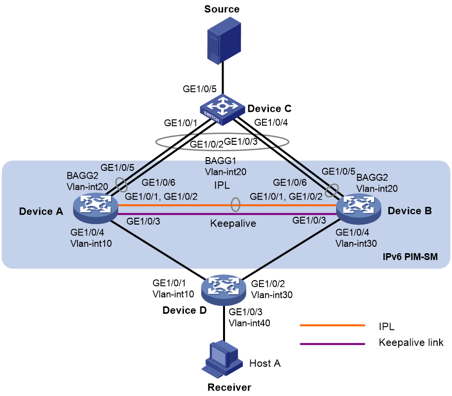
Network configuration
As shown in Figure 2:
· OSPFv3 runs on the network.
· VOD streams are sent to receiver hosts in multicast. The receivers of different subnets form stub networks, and a minimum of one receiver host exist on each stub network.
· The entire IPv6 PIM-SM domain contains only one BSR.
· Device C is a Layer 2 device attached to the multicast source. Switch A and Switch B are virtualized into a DR system, which is connected to Switch C through a multichassis aggregate link. VLAN-interface 20 interfaces on the DR system are the gateway for the multicast source.
· Host A is a multicast data receiver attached to Device D.
· The GigabitEthernet 1/0/3 interfaces on Device A and Device B are excluded from the shutdown action by DRNI MAD to set up the keepalive link.
· A VRRP group is configured on VLAN-interface 20 interfaces. In the VRRP group, Device A is the master.
· DR interfaces on Switch A and Switch B permit packets from VLAN 20 to pass through. PIM is enabled on VLAN-interface 20 of Switch A and Switch B.
· IPv6 multicast routing is enabled on Switch A and Switch B.
|
Device |
Interface |
IP address |
Device |
Interface |
IP address |
|
Device A |
Vlan-int20 |
2000::1/80 |
Device D |
Vlan-int10 |
2003::2/80 |
|
|
GE1/0/3 |
2002::1/80 |
|
Vlan-int30 |
2004::2/80 |
|
|
Vlan-int10 |
2003::1/80 |
|
Vlan-int40 |
20::1/80 |
|
|
Loop0 |
1111::1111/128 |
|
|
|
|
Device B |
Vlan-int20 |
2000::2/80 |
|
|
|
|
|
GE1/0/3 |
2002::2/80 |
|
|
|
|
|
Vlan-int30 |
2004::1/80 |
|
|
|
|
|
Loop0 |
2222::2222/128 |
|
|
|
Applicable hardware and software versions
The following matrix shows the hardware and software versions to which this configuration example is applicable:
|
Hardware |
Software version |
|
S6812 switch series S6813 switch series |
Release 6615Pxx, Release 6628Pxx |
|
S6550XE-HI switch series |
Release 6008 or later |
|
S6525XE-HI switch series |
Release 6008 or later |
|
S5850 switch series |
Not supported |
|
S5570S-EI switch series |
Not supported |
|
S5560X-EI switch series |
Release 6615Pxx, Release 6628Pxx |
|
S5560X-HI switch series |
Release 6615Pxx, Release 6628Pxx |
|
S5500V2-EI switch series |
Release 6615Pxx, Release 6628Pxx |
|
MS4520V2-30F switch |
Release 6615Pxx, Release 6628Pxx |
|
MS4520V2-30C switch MS4520V2-54C switch |
Release 6615Pxx, Release 6628Pxx |
|
MS4520V2-28S switch MS4520V2-24TP switch |
Not supported |
|
S6520X-HI switch series S6520X-EI switch series |
Release 6615Pxx, Release 6628Pxx |
|
S6520X-SI switch series S6520-SI switch series |
Release 6615Pxx, Release 6628Pxx |
|
S5000-EI switch series |
Release 6615Pxx, Release 6628Pxx |
|
MS4600 switch series |
Release 6615Pxx, Release 6628Pxx |
|
ES5500 switch series |
Release 6615Pxx, Release 6628Pxx |
|
S5560S-EI switch series S5560S-SI switch series |
Not supported |
|
S5500V3-24P-SI switch S5500V3-48P-SI switch |
Not supported |
|
S5500V3-SI switch series (except S5500V3-24P-SI and S5500V3-48P-SI) |
Not supported |
|
S5170-EI switch series |
Not supported |
|
S5130S-HI switch series S5130S-EI switch series S5130S-SI switch series S5130S-LI switch series |
Not supported |
|
S5120V2-SI switch series S5120V2-LI switch series |
Not supported |
|
S5120V3-EI switch series |
Not supported |
|
S5120V3-36F-SI switch S5120V3-28P-HPWR-SI switch S5120V3-54P-PWR-SI switch |
Not supported |
|
S5120V3-SI switch series (except S5120V3-36F-SI, S5120V3-28P-HPWR-SI, and S5120V3-54P-PWR-SI) |
Not supported |
|
S5120V3-LI switch series |
Not supported |
|
S3600V3-EI switch series |
Not supported |
|
S3600V3-SI switch series |
Not supported |
|
S3100V3-EI switch series S3100V3-SI switch series |
Not supported |
|
S5110V2 switch series |
Not supported |
|
S5110V2-SI switch series |
Not supported |
|
S5000V3-EI switch series S5000V5-EI switch series |
Not supported |
|
S5000E-X switch series S5000X-EI switch series |
Not supported |
|
E128C switch E152C switch E500C switch series E500D switch series |
Not supported |
|
MS4320V2 switch series MS4320V3 switch series MS4300V2 switch series MS4320 switch series MS4200 switch series |
Not supported |
|
WS5850-WiNet switch series |
Not supported |
|
WS5820-WiNet switch series WS5810-WiNet switch series |
Not supported |
|
WAS6000 switch series |
Not supported |
|
IE4300-12P-AC switch IE4300-12P-PWR switch IE4300-M switch series IE4320 switch series |
Not supported |
Procedures
Assigning IPv6 addresses and configuring unicast routing
Assign an IPv6 address and prefix to each interface as shown in Figure 2, and configure OSPFv3 on the switches in the IPv6 PIM-SM domain. (Details not shown.)
Configuring Device A
# Configure the DR system settings.
<DeviceA> system-view
[DeviceA] drni system-mac 1-1-1
[DeviceA] drni system-number 1
[DeviceA] drni system-priority 123
# Configure DR keepalive packet parameters.
[DeviceA] drni keepalive ipv6 destination 2002::2 source 2002::1
# Exclude the interface used for DR keepalive detection (GigabitEthernet 1/0/3) from the shutdown action by DRNI MAD.
[DeviceA] drni mad exclude interface gigabitethernet 1/0/3
# Create Layer 2 dynamic aggregate interface Bridge-Aggregation 1.
[DeviceA] interface bridge-aggregation 1
[DeviceA-Bridge-Aggregation1] link-aggregation mode dynamic
[DeviceA-Bridge-Aggregation1] quit
# Assign GigabitEthernet 1/0/1 and GigabitEthernet 1/0/2 to aggregation group 1.
[DeviceA] interface gigabitethernet 1/0/1
[DeviceA-GigabitEthernet1/0/1] port link-aggregation group 1
[DeviceA-GigabitEthernet1/0/1] quit
[DeviceA] interface gigabitethernet 1/0/2
[DeviceA-GigabitEthernet1/0/2] port link-aggregation group 1
[DeviceA-GigabitEthernet1/0/2] quit
# Create Layer 2 dynamic aggregate interface Bridge-Aggregation 2.
[DeviceA] interface bridge-aggregation 2
[DeviceA-Bridge-Aggregation2] link-aggregation mode dynamic
[DeviceA-Bridge-Aggregation2] quit
# Assign GigabitEthernet 1/0/5 and GigabitEthernet 1/0/6 to aggregation group 1.
[DeviceA] interface gigabitethernet 1/0/5
[DeviceA-GigabitEthernet1/0/5] port link-aggregation group 2
[DeviceA-GigabitEthernet1/0/5] quit
[DeviceA] interface gigabitethernet 1/0/6
[DeviceA-GigabitEthernet1/0/6] port link-aggregation group 2
[DeviceA-GigabitEthernet1/0/6] quit
# Configure Bridge-Aggregation 1 as a trunk port, assign it to all VLANs, and specify it as the IPP.
[DeviceA] interface bridge-aggregation 1
[DeviceA-Bridge-Aggregation1] port link-type trunk
[DeviceA-Bridge-Aggregation1] port trunk permit vlan all
[DeviceA-Bridge-Aggregation1] port drni intra-portal-port 1
[DeviceA-Bridge-Aggregation1] quit
# Configure Bridge-Aggregation 2 as a trunk port, assign it to VLAN 20, and assign it to a DR group.
[DeviceA] interface bridge-aggregation 2
[DeviceA-Bridge-Aggregation2] port link-type trunk
[DeviceA-Bridge-Aggregation2] port trunk permit vlan 20
[DeviceA-Bridge-Aggregation2] port drni group 1
[DeviceA-Bridge-Aggregation2] quit
# Configure VRRP group 1 on VLAN-interface 20, and set the priority of Device A to 200 for it to become the master in the VRRP group.
[DeviceA] interface vlan-interface 20
[DeviceA-Vlan-interface20] vrrp ipv6 vrid 1 virtual-ip FE80::10 link-local
[DeviceA-Vlan-interface20] vrrp ipv6 vrid 1 virtual-ip 2000::10
[DeviceA-Vlan-interface20] vrrp ipv6 vrid 1 priority 200
[DeviceA-Vlan-interface20] quit
# Enable IPv6 multicast routing, enable MLD and IPv6 PIM on VLAN-interface 10, and enable IPv6 PIM-SM on other interfaces as required.
[DeviceA] ipv6 multicast routing
[DeviceA-mrib6] quit
[DeviceA] interface vlan-interface 10
[DeviceA-Vlan-interface10] mld enable
[DeviceA-Vlan-interface10] ipv6 pim sm
[DeviceA-Vlan-interface10] quit
[DeviceA] interface vlan-interface 20
[DeviceA-Vlan-interface20] ipv6 pim sm
[DeviceA-Vlan-interface20] quit
[DeviceA] interface loopback 0
[DeviceA-LoopBack0] ipv6 pim sm
[DeviceA-LoopBack0] quit
# Specify the IPv6 address of Loopback 0 as a C-RP and a C-BSR.
[DeviceA] ipv6 pim
[DeviceA-pim6] c-rp 1111::1111
[DeviceA-pim6] c-bsr 1111::1111
[DeviceA-pim6] quit
Configuring Device B
Configure Device B in the same way you configure Device A. (Details not shown.)
Configuring Device C
# Create Layer 2 dynamic aggregate interface Bridge-Aggregation 1.
<DeviceC> system-view
[DeviceC] interface bridge-aggregation 1
[DeviceC-Bridge-Aggregation1] link-aggregation mode dynamic
[DeviceC-Bridge-Aggregation1] quit
# Assign GigabitEthernet 1/0/1 through GigabitEthernet 1/0/4 to aggregation group 1.
[DeviceC] interface range gigabitethernet 1/0/1 to gigabitethernet 1/0/4
[DeviceC-if-range] port link-aggregation group 1
[DeviceC-if-range] quit
# Configure Bridge-Aggregation 2 as a trunk port, and assign it to VLAN 20.
[DeviceC] interface bridge-aggregation 1
[DeviceC-Bridge-Aggregation1] port link-type trunk
[DeviceC-Bridge-Aggregation1] port trunk permit vlan 20
[DeviceC-Bridge-Aggregation1] quit
# Assign GigabitEthernet 1/0/5 to VLAN 20.
[DeviceC] interface gigabitethernet 1/0/5
[DeviceC-GigabitEthernet1/0/5] port access vlan 20
[DeviceC-GigabitEthernet1/0/5] quit
Configuring Device D
# Assign GigabitEthernet 1/0/1, GigabitEthernet 1/0/2, and GigabitEthernet 1/0/3 to VLAN 10, VLAN 30, and VLAN 40, respectively.
<DeviceD> system-view
[DeviceD] vlan 10
[DeviceD-vlan10] quit
[DeviceD] interface gigabitethernet1/0/1
[DeviceD-GigabitEthernet1/0/1] port access vlan 10
[DeviceD-GigabitEthernet1/0/1] quit
[DeviceD] vlan 40
[DeviceD-vlan40] quit
[DeviceD] interface gigabitethernet1/0/3
[DeviceD-GigabitEthernet1/0/3] port access vlan 40
[DeviceD] vlan 30
[DeviceD-vlan30] quit
[DeviceD] interface gigabitethernet1/0/2
[DeviceD-GigabitEthernet1/0/2] port access vlan 30
# Enable IPv6 multicast routing, and enable IPv6 PIM-SM on VLAN-interface 10 and VLAN-interface 30.
[DeviceD] ipv6 multicast routing
[DeviceD-mrib6] quit
[DeviceD] interface vlan-interface 10
[DeviceD-Vlan-interface10] ipv6 pim sm
[DeviceD-Vlan-interface10] quit
[DeviceD] vlan 30
[DeviceD-vlan30] quit
[DeviceD] interface vlan-interface 30
[DeviceD-Vlan-interface30] ipv6 pim sm
[DeviceD-Vlan-interface30] quit
# Enable MLDv2 on VLAN-interface 40.
[DeviceD] interface vlan-interface 40
[DeviceD-Vlan-interface40] mld enable
[DeviceD-Vlan-interface40] mld version 2
[DeviceD-Vlan-interface40] quit
Verifying the configuration
# Verify that Device B sends and receives keepalive packets correctly.
<DeviceB> display drni keepalive
Neighbor keepalive link status (cause): Up
Neighbor is alive for: 2128 s 421 ms
Keepalive packet transmission status:
Sent: Successful
Received: Successful
Last received keepalive packet information:
Source IP address: 2002::1
Time: 2021/12/21 15:45:15
Action: Accept
Distributed relay keepalive parameters:
Destination IP address: 2002::1
Source IP address: 2002::2
Keepalive UDP port : 6400
Keepalive VPN name : N/A
Keepalive interval : 1000 ms
Keepalive timeout : 5 sec
Keepalive hold time: 3 sec
# Verify that interfaces used by DRNI operate correctly on Device B.
<DeviceB> display drni summary
Flags: A -- Aggregate interface down, B -- No peer DR interface configured
C -- Configuration consistency check failed
IPP: BAGG1
IPP state (cause): UP
Keepalive link state (cause): UP
DR interface information
DR interface DR group Local state (cause) Peer state Remaining down time(s)
BAGG2 1 UP UP -
# Verify that the DR interface on Device B operates correctly.
<DeviceB> display link-aggregation verbose bridge-aggregation 2
Loadsharing Type: Shar -- Loadsharing, NonS -- Non-Loadsharing
Port Status: S -- Selected, U -- Unselected, I -- Individual
Port: A -- Auto port, M -- Management port, R -- Reference port
Flags: A -- LACP_Activity, B -- LACP_Timeout, C -- Aggregation,
D -- Synchronization, E -- Collecting, F -- Distributing,
G -- Defaulted, H -- Expired
Aggregate Interface: Bridge-Aggregation2
Creation Mode: Manual
Aggregation Mode: Dynamic
Loadsharing Type: Shar
Management VLANs: None
System ID: 0x7b, 0001-0001-0001
Local:
Port Status Priority Index Oper-Key Flag
GE1/0/5(R) S 32768 32770 40001 {ACDEF}
GE1/0/6 S 32768 32770 40001 {ACDEF}
Remote:
Actor Priority Index Oper-Key SystemID Flag
GE1/0/5 32768 2 1 0x8000, 84c4-42e5-0300 {ACDEF}
GE1/0/6 32768 2 1 0x8000, 84c4-42e5-0300 {ACDEF}
# Verify that the MLD group information on Device D is correct.
<DeviceD> display mld group
MLD groups in total: 1
Vlan-interface40(FE80::200:FCFF:FE00:3472):
MLD groups reported in total: 1
Group address: FF08::2
Last reporter: FE80::1
Uptime: 01:56:46
Expires: 00:02:43
# Verify that IPv6 PIM routing entries have been created on Device B.
<DeviceB> display ipv6 pim routing-table
Total 1 (*, G) entries; 1 (S, G) entries
(*, FF08::2)
RP: 2222::2222(local)
Protocol: pim-sm, Flag: WC
UpTime: 00:17:51
Upstream interface: Register-Tunnel0
Upstream neighbor: NULL
RPF prime neighbor: NULL
Downstream interface information:
Total number of downstream interfaces: 1
1: Vlan-interface30
Protocol: pim-sm, UpTime: 00:17:51, Expires: 00:02:39
(2000::111, FF08::2)
RP: 2222::2222(local)
Protocol: pim-sm, Flag: SPT LOC ACT 2MVPN
UpTime: 00:17:54
Upstream interface: Vlan-interface20
Upstream neighbor: NULL
RPF prime neighbor: NULL
Downstream interface information:
Total number of downstream interfaces: 1
1: Vlan-interface30
Protocol: pim-sm, UpTime: 00:17:54, Expires: 00:02:36
# Verify that IPv6 multicast forwarding entries have been created on Device B.
<DeviceB> display ipv6 multicast forwarding-table
Total 1 entries, 1 matched
00001. (2000::111, FF08::2)
Flags: 0x0
Uptime: 00:08:27, Timeout in: 00:03:27
Incoming interface: Vlan-interface20
List of 1 outgoing interfaces:
1: Vlan-interface30
Matched 5 packets(71681 bytes), Wrong If 0 packets
Forwarded 5 packets(71681 bytes)
# Verify that Device A does not create IPv6 PIM routing entries or multicast forwarding entries, which indicates that Device B forwards all multicast traffic to the receiver. (Details not shown.)
Configuration files
· Device A:
#
sysname DeviceA
#
ospfv3 1
router-id 2.2.2.2
area 0.0.0.0
#
vlan 10
#
vlan 20
#
interface Bridge-Aggregation1
port link-type trunk
port trunk permit vlan all
link-aggregation mode dynamic
port drni intra-portal-port 1
#
interface Bridge-Aggregation2
port link-type trunk
port trunk permit vlan 1 20
link-aggregation mode dynamic
port drni group 1
#
interface LoopBack0
ospfv3 1 area 0.0.0.0
ipv6 pim sm
ipv6 address 1111::1111/128
#
interface Vlan-interface10
ospfv3 1 area 0.0.0.0
ipv6 pim sm
ipv6 address 2003::1/80
#
interface Vlan-interface20
ospfv3 1 area 0.0.0.0
ipv6 pim sm
ipv6 address 2000::1/80
vrrp ipv6 vrid 1 virtual-ip FE80::10 link-local
vrrp ipv6 vrid 1 virtual-ip 2000::10
vrrp ipv6 vrid 1 priority 200
#
interface GigabitEthernet1/0/3
ipv6 address 2002::1/80
#
interface GigabitEthernet1/0/5
port link-type trunk
port trunk permit vlan 1 20
port link-aggregation group 2
#
interface GigabitEthernet1/0/6
port link-type trunk
port trunk permit vlan 1 20
port link-aggregation group 2
#
interface GigabitEthernet1/0/4
port access vlan 10
#
interface GigabitEthernet1/0/1
port link-type trunk
port trunk permit vlan 1 20
port link-aggregation group 1
#
interface GigabitEthernet1/0/2
port link-type trunk
port trunk permit vlan 1 20
port link-aggregation group 1
#
ipv6 multicast routing
#
ipv6 pim
c-bsr 1111::1111
c-rp 1111::1111
#
drni system-mac 0001-0001-0001
drni system-number 1
drni system-priority 123
drni keepalive ipv6 destination 2002::2 source 2002::1
drni mad exclude interface GigabitEthernet1/0/3
#
· Device B:
#
sysname DeviceB
#
ospfv3 1
router-id 3.3.3.3
area 0.0.0.0
#
vlan 20
#
vlan 30
#
interface Bridge-Aggregation1
port link-type trunk
port trunk permit vlan all
link-aggregation mode dynamic
port drni intra-portal-port 1
#
interface Bridge-Aggregation2
port link-type trunk
port trunk permit vlan 1 20
link-aggregation mode dynamic
port drni group 1
#
interface LoopBack0
ospfv3 1 area 0.0.0.0
ipv6 pim sm
ipv6 address 2222::2222/128
#
interface Vlan-interface20
ospfv3 1 area 0.0.0.0
ipv6 pim sm
ipv6 address 2000::2/80
vrrp ipv6 vrid 1 virtual-ip FE80::10 link-local
vrrp ipv6 vrid 1 virtual-ip 2000::10
vrrp ipv6 vrid 1 priority 100
#
interface Vlan-interface30
ospfv3 1 area 0.0.0.0
ipv6 pim sm
ipv6 address 2004::1/80
#
interface GigabitEthernet1/0/3
ospfv3 1 area 0.0.0.0
ipv6 address 2002::2/80
#
interface GigabitEthernet1/0/5
port link-type trunk
port trunk permit vlan 1 20
port link-aggregation group 2
#
interface GigabitEthernet1/0/6
port link-type trunk
port trunk permit vlan 1 20
port link-aggregation group 2
#
interface GigabitEthernet1/0/4
port access vlan 30
#
interface GigabitEthernet1/0/1
port link-type trunk
port trunk permit vlan 1 20
port link-aggregation group 1
#
interface GigabitEthernet1/0/2
port link-type trunk
port trunk permit vlan 1 20
port link-aggregation group 1
#
ipv6 multicast routing
#
ipv6 pim
c-bsr 2222::2222
c-rp 2222::2222
#
drni system-mac 0001-0001-0001
drni system-number 2
drni system-priority 123
drni keepalive ipv6 destination 2002::1 source 2002::2
drni mad exclude interface GigabitEthernet1/0/3
#
· Device C:
#
sysname DeviceC
#
vlan 20
#
interface Bridge-Aggregation1
port link-type trunk
port trunk permit vlan 1 20
link-aggregation mode dynamic
#
interface LoopBack1
ipv6 address FE80::2 link-local
#
interface GigabitEthernet1/0/5
port access vlan 20
#
interface GigabitEthernet1/0/1
port link-type trunk
port trunk permit vlan 1 20
port link-aggregation group 1
#
interface GigabitEthernet1/0/2
port link-type trunk
port trunk permit vlan 1 20
port link-aggregation group 1
#
interface GigabitEthernet1/0/3
port link-type trunk
port trunk permit vlan 1 20
port link-aggregation group 1
#
interface GigabitEthernet1/0/4
port link-type trunk
port trunk permit vlan 1 20
port link-aggregation group 1
#
· Device D:
#
sysname DeviceD
#
ospfv3 1
router-id 4.4.4.4
area 0.0.0.0
#
vlan 10
#
vlan 40
#
vlan 30
#
interface Vlan-interface10
ospfv3 1 area 0.0.0.0
ipv6 pim sm
ipv6 address 2003::2/80
#
interface Vlan-interface40
ospfv3 1 area 0.0.0.0
ipv6 address 20::1/80
mld enable
mld version 2
#
interface Vlan-interface30
ospfv3 1 area 0.0.0.0
ipv6 pim sm
ipv6 address 2004::2/80
#
interface GigabitEthernet1/0/3
port access vlan 40
#
interface GigabitEthernet1/0/1
port access vlan 10
#
interface GigabitEthernet1/0/2
port access vlan 30
#
ipv6 multicast routing
#
pim
#
