- Table of Contents
-
- H3C Fixed Port Campus Switches Configuration Examples-6W104
- 00-Applicable hardware and software versions
- 01-Login Management Configuration Examples
- 02-RBAC Configuration Examples
- 03-Software Upgrade Examples
- 04-ISSU Configuration Examples
- 05-Software Patching Examples
- 06-Ethernet Link Aggregation Configuration Examples
- 07-Port Isolation Configuration Examples
- 08-Spanning Tree Configuration Examples
- 09-VLAN Configuration Examples
- 10-VLAN Tagging Configuration Examples
- 11-DHCP Snooping Configuration Examples
- 12-Cross-Subnet Dynamic IP Address Allocation Configuration Examples
- 13-IPv6 over IPv4 Tunneling with OSPFv3 Configuration Examples
- 14-IPv6 over IPv4 GRE Tunnel Configuration Examples
- 15-GRE with OSPF Configuration Examples
- 16-OSPF Configuration Examples
- 17-IS-IS Configuration Examples
- 18-BGP Configuration Examples
- 19-Policy-Based Routing Configuration Examples
- 20-OSPFv3 Configuration Examples
- 21-IPv6 IS-IS Configuration Examples
- 22-Routing Policy Configuration Examples
- 23-IGMP Snooping Configuration Examples
- 24-IGMP Configuration Examples
- 25-MLD Snooping Configuration Examples
- 26-IPv6 Multicast VLAN Configuration Examples
- 27-ACL Configuration Examples
- 28-Traffic Policing Configuration Examples
- 29-GTS and Rate Limiting Configuration Examples
- 30-Traffic Filtering Configuration Examples
- 31-AAA Configuration Examples
- 32-Port Security Configuration Examples
- 33-Portal Configuration Examples
- 34-SSH Configuration Examples
- 35-IP Source Guard Configuration Examples
- 36-Ethernet OAM Configuration Examples
- 37-CFD Configuration Examples
- 38-DLDP Configuration Examples
- 39-VRRP Configuration Examples
- 40-BFD Configuration Examples
- 41-NTP Configuration Examples
- 42-SNMP Configuration Examples
- 43-NQA Configuration Examples
- 44-Mirroring Configuration Examples
- 45-sFlow Configuration Examples
- 46-OpenFlow Configuration Examples
- 47-MAC Address Table Configuration Examples
- 48-Static Multicast MAC Address Entry Configuration Examples
- 49-IP Unnumbered Configuration Examples
- 50-MVRP Configuration Examples
- 51-MCE Configuration Examples
- 52-Attack Protection Configuration Examples
- 53-Smart Link Configuration Examples
- 54-RRPP Configuration Examples
- 55-BGP Route Selection Configuration Examples
- 56-IS-IS Route Summarization Configuration Examples
- 57-VXLAN Configuration Examples
- 58-DRNI Configuration Examples
- 59-IRF 3.1 Configuration Examples
- 60-PTP Configuration Examples
- 61-S-MLAG Configuration Examples
- 62-Puppet Configuration Examples
- 63-802.1X Configuration Examples
- 64-MAC Authentication Configuration Examples
- 65-ISATAP Tunnel and 6to4 Tunnel Configuration Examples
- 66-BIDIR-PIM Configuration Examples
- 67-Congestion Avoidance and Queue Scheduling Configuration Examples
- 68-Basic MPLS Configuration Examples
- 69-MPLS L3VPN Configuration Examples
- 70-MPLS OAM Configuration Examples
- 71-EVPN-DCI over an MPLS L3VPN Network Configuration Examples
- 72-DRNI and EVPN Configuration Examples
- 73-Multicast VPN Configuration Examples
- 74-MPLS TE Configuration Examples
- 75-Control Plane-Based QoS Policy Configuration Examples
- 76-Priority Mapping and Queue Scheduling Configuration Examples
- 77-ARP Attack Protection Configuration Examples
- 78-IRF Software Upgrade Configuration Examples
- 79-IRF Member Replacement Configuration Examples
- 80-Layer 3 Multicast on Multicast Source-Side DR System Configuration Examples
- 81-EVPN Multicast Configuration Examples
- Related Documents
-
| Title | Size | Download |
|---|---|---|
| 59-IRF 3.1 Configuration Examples | 133.15 KB |
Contents
Example: Setting up an IRF 3.1 system
Applicable hardware and software versions
Parent IRF fabric and PEX hardware compatibility
Configuring cascade ports for PEXs on the parent fabric
Configuring the gateway settings on the IRF 3.1 system
Configuring access layer devices
Introduction
This document provides examples for setting up an IRF 3.1 system.
IRF 3.1 integrates multiple lower-layer devices with a higher-layer IRF fabric to provide high-density, low-cost connectivity at the access layer. IRF 3.1 is implemented based on IEEE 802.1BR.
In an IRF 3.1 system, the higher-layer IRF fabric is called the parent fabric and the lower-layer devices are called bridge port extenders (PEXs). You manage and configure the PEXs from the parent fabric as if they were interface modules on the parent fabric.
Prerequisites
The configuration examples in this document were created and verified in a lab environment, and all the devices were started with the factory default configuration. When you are working on a live network, make sure you understand the potential impact of every command on your network.
This document assumes that you have basic knowledge of IRF 3.1.
Example: Setting up an IRF 3.1 system
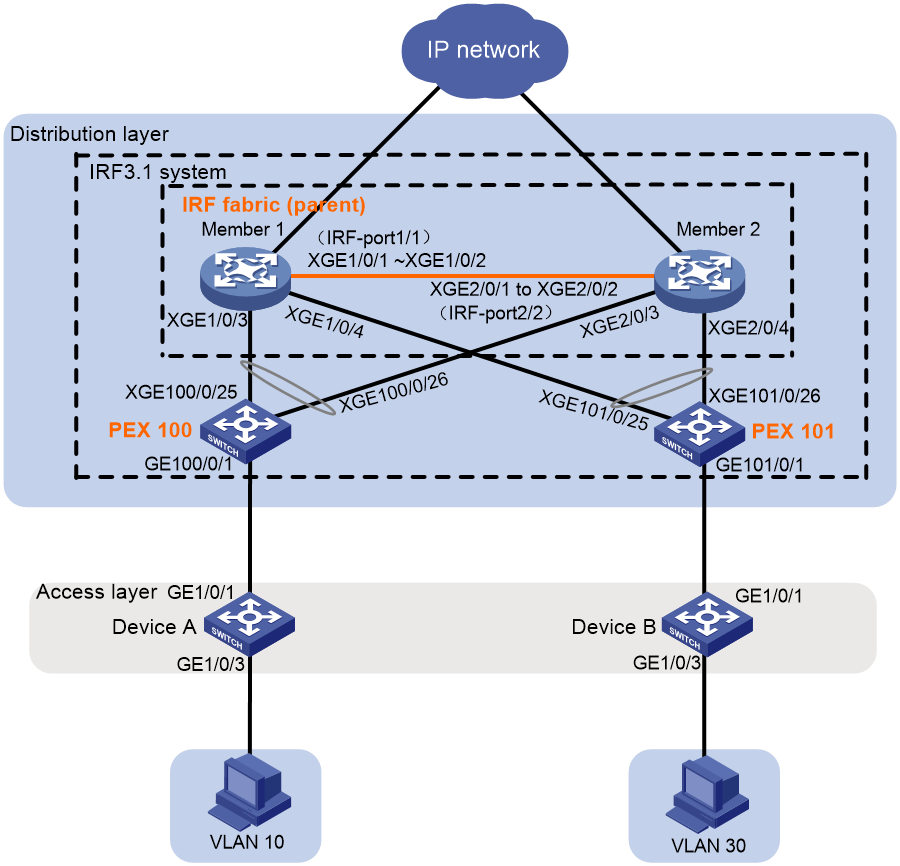
Network configuration
As shown in Figure 1:
· Use Member 1 and Member 2 to set up an IRF fabric at the distribution layer.
· Use the IRF fabric as the parent fabric and attach PEXs to the parent fabric to set up an IRF 3.1 system.
· The IRF 3.1 system acts as the gateway for users in VLANs 10 and 30.
Applicable hardware and software versions
The following matrix shows the hardware and software versions to which this configuration example is applicable:
|
Hardware |
Software version |
|
S6812 switch series S6813 switch series |
Not supported |
|
S6550XE-HI switch series |
Not supported |
|
S6525XE-HI switch series |
Not supported |
|
S5850 switch series |
Not supported |
|
S5570S-EI switch series |
Not supported |
|
S5560X-EI switch series |
Supported: Release 63xx, Release 65xx Not supported: Release 6615Pxx, Release 6628Pxx |
|
S5560X-HI switch series |
Supported: Release 63xx, Release 65xx Not supported: Release 6615Pxx, Release 6628Pxx |
|
S5500V2-EI switch series |
Not supported |
|
MS4520V2-30F switch |
Not supported |
|
MS4520V2-30C switch MS4520V2-54C switch |
Not supported |
|
MS4520V2-28S switch MS4520V2-24TP switch |
Not supported |
|
S6520X-HI switch series S6520X-EI switch series |
Supported: Release 63xx, Release 65xx Not supported: Release 6615Pxx, Release 6628Pxx |
|
S6520X-SI switch series S6520-SI switch series |
Supported: Release 63xx, Release 65xx Not supported: Release 6615Pxx, Release 6628Pxx |
|
S5000-EI switch series |
Supported: Release 63xx, Release 65xx Not supported: Release 6615Pxx, Release 6628Pxx |
|
MS4600 switch series |
Supported: Release 63xx, Release 65xx Not supported: Release 6615Pxx, Release 6628Pxx |
|
ES5500 switch series |
Supported: Release 63xx, Release 65xx Not supported: Release 6615Pxx, Release 6628Pxx |
|
S5560S-EI switch series S5560S-SI switch series |
Not supported |
|
S5500V3-24P-SI switch S5500V3-48P-SI switch |
Not supported |
|
S5500V3-SI switch series (except the S5500V3-24P-SI and S5500V3-48P-SI switches) |
Not supported |
|
S5170-EI switch series |
Not supported |
|
S5130S-HI switch series S5130S-EI switch series S5130S-SI switch series S5130S-LI switch series |
Not supported |
|
S5120V2-SI switch series S5120V2-LI switch series |
Not supported |
|
S5120V3-EI switch series |
Not supported |
|
S5120V3-36F-SI switch S5120V3-28P-HPWR-SI switch S5120V3-54P-PWR-SI switch |
Not supported |
|
S5120V3-SI switch series (except the S5120V3-36F-SI, S5120V3-28P-HPWR-SI, and S5120V3-54P-PWR-SI switches) |
Not supported |
|
S5120V3-LI switch series |
Not supported |
|
S3600V3-EI switch series |
Not supported |
|
S3600V3-SI switch series |
Not supported |
|
S3100V3-EI switch series S3100V3-SI switch series |
Not supported |
|
S5110V2 switch series |
Not supported |
|
S5110V2-SI switch series |
Not supported |
|
S5000V3-EI switch series S5000V5-EI switch series |
Not supported |
|
S5000E-X switch series S5000X-EI switch series |
Not supported |
|
E128C switch E152C switch E500C switch series E500D switch series |
Not supported |
|
MS4320V2 switch series MS4320V3 switch series MS4300V2 switch series MS4320 switch series MS4200 switch series |
Not supported |
|
WS5850-WiNet switch series |
Not supported |
|
WS5820-WiNet switch series WS5810-WiNet switch series |
Not supported |
|
WAS6000 switch series |
Not supported |
|
IE4300-12P-AC switch IE4300-12P-PWR switch IE4300-M switch series IE4320 switch series |
Not supported |
Parent IRF fabric and PEX hardware compatibility
|
Parent IRF fabric |
PEX |
|
S5560X-EI switch series |
· S5560X-EI switch series · FS4100 Switch Series |
|
S5560X-HI switch series |
FS4100 switch series |
|
S6520X-HI switch series S6520X-EI switch series |
FS4100 switch series |
|
S6520X-SI switch series S6520-SI switch series |
FS4100 switch series |
|
S5000-EI switch series |
FS4100 switch series |
|
MS4600 switch series |
FS4100 switch series |
|
ES5500 switch series |
ES4100 switch series |
Restrictions and guidelines
To assign extended ports on multiple PEXs to the same Layer 2 extended-link aggregation group, make sure the PEXs meet the following requirements:
· The PEXs belong to the same switch series.
· The PEXs are in the same PEX group.
· The PEXs are at the same tier.
The FS4100 switch series and ES4100 switch series do not support Layer 2 extended-link aggregate interfaces. You can connect a downstream access device to an FS4100 or ES4100 PEX only through a single link.
Prerequisites
On PEXs, only some high-speed ports can act as member interfaces of upstream ports. Before you set up an IRF 3.1 system, use either of the following methods to identify these ports and select upstream member interfaces from among them as needed:
· If you have not placed the switch in PEX mode, use the virtual technologies configuration guide (or IRF configuration guide) for the switch to identify candidate upstream member interfaces.
· If the switch has been placed in PEX mode, identify the candidate upstream member interfaces from the CLI:
a. Execute the probe command to enter probe view.
b. Execute the display system internal pex upstreamport command.
Table 1 lists the candidate upstream member interfaces on the PEXs to which this example is applicable:
Table 1 Candidate upstream member interfaces on the PEXs
|
PEX |
Candidate upstream member interfaces |
|
S5560X-EI switch series |
The two highest numbered ports on the front panel |
|
FS4100 switch series |
The two highest numbered ports on the front panel |
|
ES4100 switch series |
The two highest numbered 10/100/1000BASE-T autosensing Ethernet ports and the two highest numbered SFP ports. Make sure the upstream member interfaces belong to the same type. |
Procedures
Setting up the parent fabric
1. Configure Member 1:
# Place the device in 802.1BR mode.
<Sysname> system-view
[Sysname] switch-mode 2
# Set the device operating mode to switch mode. This step is required only for setting up an S5560X-EI parent IRF fabric.
[Sysname] pex system-working-mode switch
# Shut down Ten-GigabitEthernet 1/0/1 and Ten-GigabitEthernet 1/0/2.
[Sysname] interface range ten-gigabitethernet 1/0/1 to ten-gigabitethernet 1/0/2
[Sysname-if-range] shutdown
[Sysname-if-range] quit
# Bind Ten-GigabitEthernet 1/0/1 and Ten-GigabitEthernet 1/0/2 to IRF-port 1/1.
[Sysname] irf-port 1/1
[Sysname-irf-port1/1] port group interface ten-gigabitethernet 1/0/1
[Sysname-irf-port1/1] port group interface ten-gigabitethernet 1/0/2
[Sysname-irf-port1/1] quit
# Bring up Ten-GigabitEthernet 1/0/1 and Ten-GigabitEthernet 1/0/2 and save the configuration.
[Sysname] interface range ten-gigabitethernet 1/0/1 to ten-gigabitethernet 1/0/2
[Sysname-if-range] undo shutdown
[Sysname-if-range] quit
[Sysname] save
# Activate the IRF port configuration.
[Sysname] irf-port-configuration active
2. Configure Member 2:
# Place the device in 802.1BR mode.
<Sysname> system-view
[Sysname] switch-mode 2
# Set the device operating mode to switch mode. This step is required only for setting up an S5560X-EI parent IRF fabric.
[Sysname] pex system-working-mode switch
# Change the IRF member ID to 2 and reboot the device for the new member ID to take effect.
[Sysname] irf member 1 renumber 2
Renumbering the member ID may result in configuration change or loss. Continue? [Y/N]:y
[Sysname] quit
<Sysname> reboot
# Log in to the device and shut down Ten-GigabitEthernet 2/0/1 and Ten-GigabitEthernet 2/0/2.
<Sysname> system-view
[Sysname] interface range ten-gigabitethernet 2/0/1 to ten-gigabitethernet 2/0/2
[Sysname-if-range] shutdown
[Sysname-if-range] quit
# Bind Ten-GigabitEthernet 2/0/1 and Ten-GigabitEthernet 2/0/2 to IRF-port 2/2.
[Sysname] irf-port 2/2
[Sysname-irf-port2/2] port group interface ten-gigabitethernet 2/0/1
[Sysname-irf-port2/2] port group interface ten-gigabitethernet 2/0/2
[Sysname-irf-port2/2] quit
# Bring up Ten-GigabitEthernet 2/0/1 and Ten-GigabitEthernet 2/0/2 and save the configuration.
[Sysname] interface range ten-gigabitethernet 2/0/1 to ten-gigabitethernet 2/0/2
[Sysname-if-range] undo shutdown
[Sysname-if-range] quit
[Sysname] save
# Connect the IRF physical interfaces on Member 2 to the IRF physical interfaces on Member 1. (Details not shown.)
# Activate the IRF port configuration on Member 2.
[Sysname] irf-port-configuration active
Member 1 and Member 2 perform master election. The device that fails the election will reboot automatically to form an IRF fabric with the other device.
Configuring cascade ports for PEXs on the parent fabric
# Enter system view.
<Sysname> system-view
# Enable LLDP globally.
[Sysname] lldp global enable
# Create PEX group 1.
[Sysname] pex group 1
[Sysname-pex-group-1] quit
# Create Layer 2 aggregate interface Bridge-Aggregation 100. The aggregate interface will act as the cascade port connecting to the PEX in slot 100. For easy maintenance, this example assigns the aggregate interface the same number as the PEX virtual slot.
[Sysname] interface bridge-aggregation 100
# Enable PEX connection capability on Bridge-Aggregation 100 and assign Bridge-Aggregation 100 to PEX group 1.
[Sysname-Bridge-Aggregation100] pex-capability enable group 1
The aggregate interface was automatically set to dynamic aggregation mode and configured as an STP edge port.
# Assign virtual slot number 100 to the PEX.
[Sysname-Bridge-Aggregation100] pex associate slot 100
[Sysname-Bridge-Aggregation100] quit
# Enable LLDP on Ten-GigabitEthernet 1/0/3 and Ten-GigabitEthernet 2/0/3 in interface range view. By default, LLDP is enabled on a port.
[Sysname] interface range ten-gigabitethernet 1/0/3 ten-gigabitethernet 2/0/3
[Sysname-if-range] lldp enable
# Assign Ten-GigabitEthernet 1/0/3 and Ten-GigabitEthernet 2/0/3 to aggregation group 100. The ports will act as the cascade member interfaces.
[Sysname-if-range] port link-aggregation group 100
[Sysname-if-range] quit
# Create Layer 2 aggregate interface Bridge-Aggregation 101. The aggregate interface will act as the cascade port connecting to the PEX in slot 101.
[Sysname] interface bridge-aggregation 101
# Enable PEX connection capability on Bridge-Aggregation 101 and assign the interface to PEX group 1.
[Sysname-Bridge-Aggregation101] pex-capability enable group 1
The aggregate interface was automatically set to dynamic aggregation mode and configured as an STP edge port.
# Assign virtual slot number 101 to the PEX.
[Sysname-Bridge-Aggregation101] pex associate slot 101
[Sysname-Bridge-Aggregation101] quit
# Enable LLDP on Ten-GigabitEthernet 1/0/4 and Ten-GigabitEthernet 2/0/4 in interface range view. By default, LLDP is enabled on a port.
[Sysname] interface range ten-gigabitethernet 1/0/4 ten-gigabitethernet 2/0/4
[Sysname-if-range] lldp enable
# Assign Ten-GigabitEthernet 1/0/4 and Ten-GigabitEthernet 2/0/4 to aggregation group 101. The ports will act as the cascade member interfaces.
[Sysname-if-range] port link-aggregation group 101
[Sysname-if-range] quit
Configuring PEXs
Configure the devices to be used as PEXs to operate in auto or PEX mode. This example uses PEX 100 to describe the configuration procedure. You configure PEX 101 in the same way PEX 100 is configured.
1. Configure PEX 100 to operate in auto mode:
|
|
IMPORTANT: Skip this step if the PEXs are FS4100 switches or ES4100 switches. |
# Change the operating mode to auto mode. By default, the operating mode is auto.
<Sysname> system-view
[Sysname] pex system-working-mode auto
# Save the running configuration.
[Sysname] save
2. Select upstream member interfaces.
In this example, Ten-GigabitEthernet 1/0/25 and Ten-GigabitEthernet 1/0/26 are used. For information about candidate upstream member interfaces, see the configuration and installation guides for the PEX. (Details not shown.)
3. Connect the upstream member interfaces on PEX 100 to the cascade member interfaces on the parent fabric as shown in Figure 1. (Details not shown.)
Configuring the gateway settings on the IRF 3.1 system
# Enter system view.
<Sysname> system-view
# Create VLANs 10 and 30.
[Sysname] vlan 10 30
# Create VLAN-interface 10 and assign IP address 192.168.1.1/24 to the VLAN interface.
[Sysname] interface vlan-interface 10
[Sysname-Vlan-interface10] ip address 192.168.1.1 24
[Sysname-Vlan-interface10] quit
# Create VLAN-interface 30 and assign IP address 192.168.3.1/24 to the VLAN interface.
[Sysname] interface vlan-interface 30
[Sysname-Vlan-interface30] ip address 192.168.3.1 24
[Sysname-Vlan-interface30] quit
# Assign GigabitEthernet 100/0/1 to VLAN 10.
[Sysname] interface gigabitethernet 100/0/1
[Sysname-GigabitEthernet100/0/1] port access vlan 10
[Sysname-GigabitEthernet100/0/1] quit
# Assign GigabitEthernet 101/0/1 to VLAN 30.
[Sysname] interface gigabitethernet 101/0/1
[Sysname-GigabitEthernet101/0/1] port access vlan 30
[Sysname-GigabitEthernet101/0/1] quit
Configuring access layer devices
1. Configure Device A:
# Enter system view.
<Sysname> system-view
# Create VLAN 10.
[Sysname] vlan 10
[Sysname-vlan10] quit
# Assign GigabitEthernet 1/0/1 and GigabitEthernet 1/0/3 to VLAN 10.
[Sysname] interface range gigabitethernet 1/0/1 gigabitethernet 1/0/3
[Sysname-if-range] port access vlan 10
[Sysname-if-range] quit
# Enter system view.
<Sysname> system-view
# Create VLAN 30.
[Sysname] vlan 30
[Sysname-vlan30] quit
# Assign GigabitEthernet 1/0/1 and GigabitEthernet 1/0/3 to VLAN 30.
[Sysname] interface range gigabitethernet 1/0/1 gigabitethernet 1/0/3
[Sysname-if-range] port access vlan 30
[Sysname-if-range] quit
Verifying the configuration
# Use the display device command to display device information on the parent fabric. If the IRF 3.1 system has been set up, the system displays information about both parent IRF member devices and PEXs. (Details not shown.)
# Test the gateway service of the IRF 3.1 system. Verify that hosts in VLANs 10 and 30 can ping each other. (Details not shown.)
Configuration files
· IRF 3.1 system:
#
pex group 1
#
lldp global enable
#
pex system-working-mode switch
#
vlan 10
#
vlan 30
#
irf-port 1/1
port group interface Ten-GigabitEthernet1/0/1
port group interface Ten-GigabitEthernet1/0/2
#
irf-port 2/2
port group interface Ten-GigabitEthernet2/0/1
port group interface Ten-GigabitEthernet2/0/2
#
interface Bridge-Aggregation100
pex-capability enable group 1
pex associate slot 100
link-aggregation mode dynamic
stp edged-port
#
interface Bridge-Aggregation101
pex-capability enable group 1
pex associate slot 101
link-aggregation mode dynamic
stp edged-port
#
interface Vlan-interface10
ip address 192.168.1.1 255.255.255.0
#
interface Vlan-interface30
ip address 192.168.3.1 255.255.255.0
#
interface GigabitEthernet100/0/1
port link-mode bridge
port access vlan 10
#
interface GigabitEthernet101/0/1
port link-mode bridge
port access vlan 30
#
interface Ten-GigabitEthernet1/0/3
port link-mode bridge
port link-aggregation group 100
#
interface Ten-GigabitEthernet1/0/4
port link-mode bridge
port link-aggregation group 101
#
interface Ten-GigabitEthernet2/0/3
port link-mode bridge
port link-aggregation group 100
#
interface Ten-GigabitEthernet2/0/4
port link-mode bridge
port link-aggregation group 101
· Device A:
#
vlan 10
#
interface GigabitEthernet1/0/1
port link-mode bridge
port access vlan 10
#
interface GigabitEthernet1/0/3
port link-mode bridge
port access vlan 10
· Device B:
#
vlan 30
#
interface GigabitEthernet1/0/1
port link-mode bridge
port access vlan 30
#
interface GigabitEthernet1/0/3
port link-mode bridge
port access vlan 30
