- Table of Contents
-
- H3C Fixed Port Campus Switches Configuration Examples-6W104
- 00-Applicable hardware and software versions
- 01-Login Management Configuration Examples
- 02-RBAC Configuration Examples
- 03-Software Upgrade Examples
- 04-ISSU Configuration Examples
- 05-Software Patching Examples
- 06-Ethernet Link Aggregation Configuration Examples
- 07-Port Isolation Configuration Examples
- 08-Spanning Tree Configuration Examples
- 09-VLAN Configuration Examples
- 10-VLAN Tagging Configuration Examples
- 11-DHCP Snooping Configuration Examples
- 12-Cross-Subnet Dynamic IP Address Allocation Configuration Examples
- 13-IPv6 over IPv4 Tunneling with OSPFv3 Configuration Examples
- 14-IPv6 over IPv4 GRE Tunnel Configuration Examples
- 15-GRE with OSPF Configuration Examples
- 16-OSPF Configuration Examples
- 17-IS-IS Configuration Examples
- 18-BGP Configuration Examples
- 19-Policy-Based Routing Configuration Examples
- 20-OSPFv3 Configuration Examples
- 21-IPv6 IS-IS Configuration Examples
- 22-Routing Policy Configuration Examples
- 23-IGMP Snooping Configuration Examples
- 24-IGMP Configuration Examples
- 25-MLD Snooping Configuration Examples
- 26-IPv6 Multicast VLAN Configuration Examples
- 27-ACL Configuration Examples
- 28-Traffic Policing Configuration Examples
- 29-GTS and Rate Limiting Configuration Examples
- 30-Traffic Filtering Configuration Examples
- 31-AAA Configuration Examples
- 32-Port Security Configuration Examples
- 33-Portal Configuration Examples
- 34-SSH Configuration Examples
- 35-IP Source Guard Configuration Examples
- 36-Ethernet OAM Configuration Examples
- 37-CFD Configuration Examples
- 38-DLDP Configuration Examples
- 39-VRRP Configuration Examples
- 40-BFD Configuration Examples
- 41-NTP Configuration Examples
- 42-SNMP Configuration Examples
- 43-NQA Configuration Examples
- 44-Mirroring Configuration Examples
- 45-sFlow Configuration Examples
- 46-OpenFlow Configuration Examples
- 47-MAC Address Table Configuration Examples
- 48-Static Multicast MAC Address Entry Configuration Examples
- 49-IP Unnumbered Configuration Examples
- 50-MVRP Configuration Examples
- 51-MCE Configuration Examples
- 52-Attack Protection Configuration Examples
- 53-Smart Link Configuration Examples
- 54-RRPP Configuration Examples
- 55-BGP Route Selection Configuration Examples
- 56-IS-IS Route Summarization Configuration Examples
- 57-VXLAN Configuration Examples
- 58-DRNI Configuration Examples
- 59-IRF 3.1 Configuration Examples
- 60-PTP Configuration Examples
- 61-S-MLAG Configuration Examples
- 62-Puppet Configuration Examples
- 63-802.1X Configuration Examples
- 64-MAC Authentication Configuration Examples
- 65-ISATAP Tunnel and 6to4 Tunnel Configuration Examples
- 66-BIDIR-PIM Configuration Examples
- 67-Congestion Avoidance and Queue Scheduling Configuration Examples
- 68-Basic MPLS Configuration Examples
- 69-MPLS L3VPN Configuration Examples
- 70-MPLS OAM Configuration Examples
- 71-EVPN-DCI over an MPLS L3VPN Network Configuration Examples
- 72-DRNI and EVPN Configuration Examples
- 73-Multicast VPN Configuration Examples
- 74-MPLS TE Configuration Examples
- 75-Control Plane-Based QoS Policy Configuration Examples
- 76-Priority Mapping and Queue Scheduling Configuration Examples
- 77-ARP Attack Protection Configuration Examples
- 78-IRF Software Upgrade Configuration Examples
- 79-IRF Member Replacement Configuration Examples
- 80-Layer 3 Multicast on Multicast Source-Side DR System Configuration Examples
- 81-EVPN Multicast Configuration Examples
- Related Documents
-
| Title | Size | Download |
|---|---|---|
| 60-PTP Configuration Examples | 265.49 KB |
Example: Configuring Layer 2 IEEE 1588v2 PTP
Applicable hardware and software versions
Example: Configuring Layer 3 IEEE 1588v2 PTP in multicast mode
Applicable hardware and software versions
Example: Configuring Layer 3 IEEE 1588v2 PTP in unicast mode
Applicable hardware and software versions
Example: Configuring IEEE 802.1AS PTP
Applicable hardware and software versions
Example: Configuring SMPTE ST 2059-2 PTP in multicast mode
Applicable hardware and software versions
Example: Configuring PTP (SMPTE ST 2059-2, IPv4 UDP transport, unicast transmission)
Applicable hardware and software versions
Introduction
This document provides PTP configuration examples.
Prerequisites
This document is not restricted to specific software or hardware versions.
The configuration examples in this document were created and verified in a lab environment, and all the devices were started with the factory default configuration. When you are working on a live network, make sure you understand the potential impact of every command on your network.
This document assumes that you have basic knowledge of PTP.
Example: Configuring Layer 2 IEEE 1588v2 PTP
Network configuration
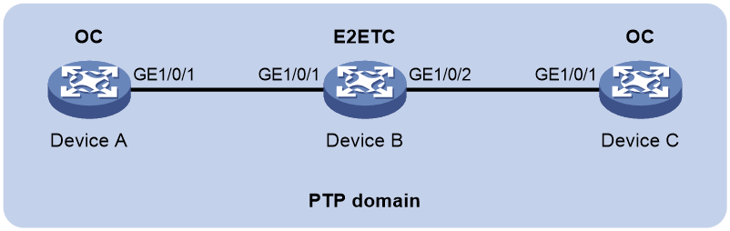
As shown in Figure 1, a PTP domain contains Device A, Device B, and Device C. Configure Layer 2 IEEE 1588v2 PTP as follows for time synchronization:
· Specify the IEEE 1588v2 PTP profile for the devices.
· Specify the OC clock node type for Device A and Device C, and E2ETC clock node type for Device B. These clock nodes elect a GM through BMC based on their respective default GM attributes.
· Use the default Request-Response delay measurement mechanism for Device A and Device C.
Applicable hardware and software versions
The following matrix shows the hardware and software versions to which this configuration example is applicable:
|
Hardware |
Software version |
|
S6812 switch series S6813 switch series |
Release 6615Pxx, Release 6628Pxx |
|
S6550XE-HI switch series |
Release 6008 and later, Release 8106Pxx |
|
S6525XE-HI switch series |
Release 6008 and later, Release 8106Pxx |
|
S5850 switch series |
Not supported |
|
S5570S-EI switch series |
Not supported |
|
S5560X-EI switch series |
Not supported |
|
S5560X-HI switch series |
Release 6615Pxx, Release 6628Pxx |
|
S5500V2-EI switch series |
Not supported |
|
MS4520V2-30F switch |
Not supported |
|
MS4520V2-30C switch MS4520V2-54C switch |
Not supported |
|
MS4520V2-28S switch MS4520V2-24TP switch |
Not supported |
|
ES5500 switch series |
Not supported |
|
S6520X-HI switch series S6520X-EI switch series |
Release 6615Pxx, Release 6628Pxx |
|
S6520X-SI switch series S6520-SI switch series |
Release 6615Pxx, Release 6628Pxx |
|
S5000-EI switch series |
Release 6615Pxx, Release 6628Pxx |
|
MS4600 switch series |
Release 6615Pxx, Release 6628Pxx |
|
S5560S-EI switch series S5560S-SI switch series |
Not supported |
|
S5500V3-24P-SI S5500V3-48P-SI |
Not supported |
|
S5500V3-SI switch series (except the S5500V3-24P-SI and S5500V3-48P-SI) |
Not supported |
|
S5170-EI switch series |
Not supported |
|
S5130S-HI switch series S5130S-EI switch series S5130S-SI switch series S5130S-LI switch series |
Not supported |
|
S5120V2-SI switch series S5120V2-LI switch series |
Not supported |
|
S5120V3-EI switch series |
Not supported |
|
S5120V3-36F-SI S5120V3-28P-HPWR-SI S5120V3-54P-PWR-SI |
Not supported |
|
S5120V3-SI switch series (except the S5120V3-36F-SI, S5120V3-28P-HPWR-SI, and S5120V3-54P-PWR-SI) |
Not supported |
|
S5120V3-LI switch series |
Not supported |
|
S3600V3-EI switch series |
Not supported |
|
S3600V3-SI switch series |
Not supported |
|
S3100V3-EI switch series S3100V3-SI switch series |
Not supported |
|
S5110V2 switch series |
Not supported |
|
S5110V2-SI switch series |
Not supported |
|
S5000V3-EI switch series S5000V5-EI switch series |
Not supported |
|
S5000E-X switch series S5000X-EI switch series |
Not supported |
|
E128C switch E152C switch E500C switch series E500D switch series |
Not supported |
|
MS4320V2 switch series MS4320V3 switch series MS4300V2 switch series MS4320 switch series MS4200 switch series |
Not supported |
|
WS5850-WiNet switch series |
Not supported |
|
WS5820-WiNet switch series WS5810-WiNet switch series |
Not supported |
|
WAS6000 switch series |
Not supported |
|
IE4300-12P-AC switch IE4300-12P-PWR switch IE4300-M switch series (except the IE4300-28P-M) IE4320 switch series (except the IE4320-28P) |
Not supported |
|
IE4300-28P-M switch IE4320-28P switch |
Release 63xx |
Procedures
Configuring Device A
# Specify the IEEE 1588v2 PTP profile.
<DeviceA> system-view
[DeviceA] ptp profile 1588v2
# Specify the OC clock node type.
[DeviceA] ptp mode oc
# Enable PTP globally.
[DeviceA] ptp global enable
# Specify a PTP domain.
[DeviceA] ptp domain 0
# Specify PTP for obtaining the time.
[DeviceA] clock protocol ptp
# Enable PTP on GigabitEthernet 1/0/1.
[DeviceA] interface gigabitethernet 1/0/1
[DeviceA-GigabitEthernet1/0/1] ptp enable
[DeviceA-GigabitEthernet1/0/1] quit
Configuring Device B
# Specify the IEEE 1588v2 PTP profile.
<DeviceB> system-view
[DeviceB] ptp profile 1588v2
# Specify the E2ETC clock node type.
[DeviceB] ptp mode e2etc
# Specify a PTP domain.
[DeviceB] ptp domain 0
# Enable PTP globally.
[DeviceB] ptp global enable
# Specify PTP for obtaining the time.
[DeviceB] clock protocol ptp
# Enable PTP on GigabitEthernet 1/0/1.
[DeviceB] interface gigabitethernet 1/0/1
[DeviceB-GigabitEthernet1/0/1] ptp enable
[DeviceB-GigabitEthernet1/0/1] quit
# Enable PTP on GigabitEthernet 1/0/2.
[DeviceB] interface gigabitethernet 1/0/2
[DeviceB-GigabitEthernet1/0/2] ptp enable
[DeviceB-GigabitEthernet1/0/2] quit
Configuring Device C
# Specify the IEEE 1588v2 PTP profile.
<DeviceC> system-view
[DeviceC] ptp profile 1588v2
# Specify the OC clock node type.
[DeviceC] ptp mode oc
# Specify a PTP domain.
[DeviceC] ptp domain 0
# Enable PTP globally.
[DeviceC] ptp global enable
# Specify PTP for obtaining the time.
[DeviceC] clock protocol ptp
# Enable PTP on GigabitEthernet 1/0/1.
[DeviceC] interface gigabitethernet 1/0/1
[DeviceC-GigabitEthernet1/0/1] ptp enable
[DeviceC-GigabitEthernet1/0/1] quit
Verifying the configuration
|
|
IMPORTANT: · The Lock status field in the output from the display ptp clock command is available only for the S6550XE-HI switch series and S6525XE-HI switch series. · The InstID field in the output from the display ptp interface brief command is available only for the S6550XE-HI switch series and S6525XE-HI switch series. |
When the network topology is stable, perform the following tasks to verify the PTP configuration:
· Use the display ptp clock command to display PTP clock information.
· Use the display ptp interface brief command to display brief information about PTP interfaces.
# Display PTP clock information on Device A.
[DeviceA] display ptp clock
PTP global state : Enabled
PTP profile : IEEE 1588 Version 2
PTP mode : OC
Slave only : No
Lock status : Unlocked
Clock ID : 000FE2-FFFE-FF0000
Clock type : Local
Clock domain : 0
Number of PTP ports : 1
Priority1 : 128
Priority2 : 128
Clock quality :
Class : 248
Accuracy : 254
Offset (log variance) : 65535
Offset from master : 0 (ns)
Mean path delay : 0 (ns)
Steps removed : 0
Local clock time : Sun Jan 15 20:57:29 2019
# Display brief information about PTP interfaces on Device A.
[DeviceA] display ptp interface brief
Name InstID State Delay mechanism Clock step Asymmetry correction
GE1/0/1 0 Master E2E Two 0
# Display PTP clock information on Device B.
[DeviceB] display ptp clock
PTP global state : Enabled
PTP profile : IEEE 1588 Version 2
PTP mode : E2ETC
Slave only : No
Lock status : Unlocked
Clock ID : 000FE2-FFFE-FF0001
Clock type : Local
Clock domain : 0
Number of PTP ports : 2
Priority1 : 128
Priority2 : 128
Clock quality :
Class : 248
Accuracy : 254
Offset (log variance) : 65535
Offset from master : N/A
Mean path delay : N/A
Steps removed : N/A
Local clock time : Sun Jan 15 20:57:29 2019
# Display brief information about PTP interfaces on Device B.
[DeviceB] display ptp interface brief
Name InstID State Delay mechanism Clock step Asymmetry correction
GE1/0/1 0 N/A E2E Two 0
GE1/0/2 0 N/A E2E Two 0
# Display PTP clock information on Device C.
[DeviceC] display ptp clock
PTP global state : Enabled
PTP profile : IEEE 1588 Version 2
PTP mode : OC
Slave only : No
Lock status : Locked
Clock ID : 000FE2-FFFE-FF0002
Clock type : Local
Clock domain : 0
Number of PTP ports : 2
Priority1 : 128
Priority2 : 128
Clock quality :
Class : 248
Accuracy : 254
Offset (log variance) : 65535
Offset from master : 25
Mean path delay : 323
Steps removed : 2
Local clock time : Sun Jan 15 20:57:29 2019
# Display brief information about PTP interfaces on Device C.
[DeviceC] display ptp interface brief
Name InstID State Delay mechanism Clock step Asymmetry correction
GE1/0/1 0 Slave E2E Two 0
The command outputs show that Device A is elected as the GM and GigabitEthernet1/0/1 on Device A is the master port.
Configuration files
· Device A and Device C:
#
clock protocol ptp
#
ptp profile 1588v2
ptp mode oc
#
interface GigabitEthernet 1/0/1
ptp enable
#
· Device B:
#
clock protocol ptp
#
ptp profile 1588v2
ptp mode e2etc
#
interface GigabitEthernet 1/0/1
ptp enable
#
interface GigabitEthernet 1/0/2
ptp enable
#
Example: Configuring Layer 3 IEEE 1588v2 PTP in multicast mode
Network configuration
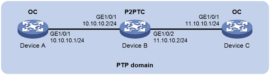
As shown in Figure 2, a PTP domain contains Device A, Device B, and Device C. Configure Layer 3 IEEE 1588v2 PTP in multicast mode as follows for time synchronization:
· Specify the IEEE 1588v2 PTP profile for the devices.
· Specify the OC clock node type for Device A and Device C, and the P2PTC clock node type for Device B. These clock nodes elect a GM through BMC based on their respective default GM attributes.
· Configure the multicast PTP transport mode and UDP (IPv4) transport protocol for the devices.
· Configure the peer delay measurement mechanism (p2p) for Device A and Device C.
Applicable hardware and software versions
The following matrix shows the hardware and software versions to which this configuration example is applicable:
|
Hardware |
Software version |
|
S6812 switch series S6813 switch series |
Release 6615Pxx, Release 6628Pxx |
|
S6550XE-HI switch series |
Release 6008 and later, Release 8106Pxx |
|
S6525XE-HI switch series |
Release 6008 and later, Release 8106Pxx |
|
S5850 switch series |
Not supported |
|
S5560X-EI switch series |
Not supported |
|
S5560X-HI switch series |
Release 6615Pxx, Release 6628Pxx |
|
S5570S-EI switch series |
Not supported |
|
S5500V2-EI switch series |
Not supported |
|
MS4520V2-30F switch |
Not supported |
|
MS4520V2-30C switch MS4520V2-54C switch |
Not supported |
|
MS4520V2-28S switch MS4520V2-24TP switch |
Not supported |
|
ES5500 switch series |
Not supported |
|
S6520X-HI switch series S6520X-EI switch series |
Release 6615Pxx, Release 6628Pxx |
|
S6520X-SI switch series S6520-SI switch series |
Release 6615Pxx, Release 6628Pxx |
|
S5000-EI switch series |
Release 6615Pxx, Release 6628Pxx |
|
MS4600 switch series |
Release 6615Pxx, Release 6628Pxx |
|
S5560S-EI switch series S5560S-SI switch series |
Not supported |
|
S5500V3-24P-SI S5500V3-48P-SI |
Not supported |
|
S5500V3-SI switch series (except the S5500V3-24P-SI and S5500V3-48P-SI) |
Not supported |
|
S5170-EI switch series |
Not supported |
|
S5130S-HI switch series S5130S-EI switch series S5130S-SI switch series S5130S-LI switch series |
Not supported |
|
S5120V2-SI switch series S5120V2-LI switch series |
Not supported |
|
S5120V3-EI switch series |
Not supported |
|
S5120V3-36F-SI S5120V3-28P-HPWR-SI S5120V3-54P-PWR-SI |
Not supported |
|
S5120V3-SI switch series (except the S5120V3-36F-SI, S5120V3-28P-HPWR-SI, and S5120V3-54P-PWR-SI) |
Not supported |
|
S5120V3-LI switch series |
Not supported |
|
S3600V3-EI switch series |
Not supported |
|
S3600V3-SI switch series |
Not supported |
|
S3100V3-EI switch series S3100V3-SI switch series |
Not supported |
|
S5110V2 switch series |
Not supported |
|
S5110V2-SI switch series |
Not supported |
|
S5000V3-EI switch series S5000V5-EI switch series |
Not supported |
|
S5000E-X switch series S5000X-EI switch series |
Not supported |
|
E128C switch E152C switch E500C switch series E500D switch series |
Not supported |
|
MS4320V2 switch series MS4320V3 switch series MS4300V2 switch series MS4320 switch series MS4200 switch series |
Not supported |
|
WS5850-WiNet switch series |
Not supported |
|
WS5820-WiNet switch series WS5810-WiNet switch series |
Not supported |
|
WAS6000 switch series |
Not supported |
|
IE4300-12P-AC switch IE4300-12P-PWR switch IE4300-M switch series (except the IE4300-28P-M) IE4320 switch series (except the IE4320-28P) |
Not supported |
|
IE4300-28P-M switch IE4320-28P switch |
Release 63xx |
Procedures
Configuring Device A
# Specify the IEEE 1588v2 PTP profile.
<DeviceA> system-view
[DeviceA] ptp profile 1588v2
# Specify the OC clock node type.
[DeviceA] ptp mode oc
# Specify a PTP domain.
[DeviceA] ptp domain 0
# Enable PTP globally.
[DeviceA] ptp global enable
# Configure the source IP address for multicast PTP transport.
[DeviceA] ptp source 10.10.10.1
# Specify PTP for obtaining the time.
[DeviceA] clock protocol ptp
# On GigabitEthernet 1/0/1, specify the UDP (IPv4) transport protocol and the peer delay measurement mechanism (p2p) and enable PTP.
[DeviceA] interface gigabitethernet 1/0/1
[DeviceA-GigabitEthernet1/0/1] ptp transport-protocol udp [DeviceA-GigabitEthernet1/0/1] ptp delay-mechanism p2p
[DeviceA-GigabitEthernet1/0/1] ptp enable
[DeviceA-GigabitEthernet1/0/1] quit
Configuring Device B
# Specify the IEEE 1588v2 PTP profile.
<DeviceB> system-view
[DeviceB] ptp profile 1588v2
# Specify the P2PTC clock node type.
[DeviceB] ptp mode p2ptc
# Specify a PTP domain.
[DeviceB] ptp domain 0
# Enable PTP globally.
[DeviceB] ptp global enable
# Configure the source IP address for multicast PTP transport.
[DeviceB] ptp source 10.10.10.2
# Specify PTP for obtaining the time.
[DeviceB] clock protocol ptp
# On GigabitEthernet 1/0/1, specify the UDP (IPv4) transport protocol and enable PTP.
[DeviceB] interface gigabitethernet 1/0/1
DeviceB-GigabitEthernet1/0/1] ptp transport-protocol udp
[DeviceB-GigabitEthernet1/0/1] ptp enable
[DeviceB-GigabitEthernet1/0/1] quit
# On GigabitEthernet 1/0/2, specify the UDP transport protocol and enable PTP.
[DeviceB] interface gigabitethernet 1/0/2
[DeviceB-GigabitEthernet1/0/2] ptp transport-protocol udp
[DeviceB-GigabitEthernet1/0/2] ptp enable
[DeviceB-GigabitEthernet1/0/2] quit
Configuring Device C
# Specify the IEEE 1588v2 PTP profile.
<DeviceC> system-view
[DeviceC] ptp profile 1588v2
# Specify the OC clock node type.
[DeviceC] ptp mode oc
# Specify a PTP domain.
[DeviceC] ptp domain 0
# Enable PTP globally.
[DeviceC] ptp global enable
# Configure the source IP address for multicast PTP transport.
[DeviceC] ptp source 11.10.10.1
# Specify PTP for obtaining the time.
[DeviceC] clock protocol ptp
# On GigabitEthernet 1/0/1, specify the UDP (IPv4) transport protocol and the peer delay measurement mechanism (p2p) and enable PTP.
[DeviceC] interface gigabitethernet 1/0/1
[DeviceC-GigabitEthernet1/0/1] ptp transport-protocol udp [DeviceC-GigabitEthernet1/0/1] ptp delay-mechanism p2p
[DeviceC-GigabitEthernet1/0/1] ptp enable
[DeviceC-GigabitEthernet1/0/1] quit
Verifying the configuration
|
|
IMPORTANT: · The Lock status field in the output from the display ptp clock command is available only for the S6550XE-HI switch series and S6525XE-HI switch series. · The InstID field in the output from the display ptp interface brief command is available only for the S6550XE-HI switch series and S6525XE-HI switch series. |
When the network topology is stable, perform the following tasks to verify the PTP configuration:
· Use the display ptp clock command to display PTP clock information.
· Use the display ptp interface brief command to display brief information about PTP interfaces.
# Display PTP clock information on Device A.
[DeviceA] display ptp clock
PTP global state : Enabled
PTP profile : IEEE 1588 Version 2
PTP mode : OC
Slave only : No
Lock status : Unlocked
Clock ID : 000FE2-FFFE-FF0000
Clock type : Local
Clock domain : 0
Number of PTP ports : 1
Priority1 : 128
Priority2 : 128
Clock quality :
Class : 248
Accuracy : 254
Offset (log variance) : 65535
Offset from master : 0 (ns)
Mean path delay : 0 (ns)
Steps removed : 0
Local clock time : Sun Jan 15 20:57:29 2019
# Display brief information about PTP interfaces on Device A.
[DeviceA] display ptp interface brief
Name InstID State Delay mechanism Clock step Asymmetry correction
GE1/0/1 0 Master P2P Two 0
# Display PTP clock information on Device B.
[DeviceB] display ptp clock
PTP global state : Enabled
PTP profile : IEEE 1588 Version 2
PTP mode : P2PTC
Slave only : No
Lock status : Unlocked
Clock ID : 000FE2-FFFE-FF0001
Clock type : Local
Clock domain : 0
Number of PTP ports : 2
Priority1 : 128
Priority2 : 128
Clock quality :
Class : 248
Accuracy : 254
Offset (log variance) : 65535
Offset from master : N/A
Mean path delay : N/A
Steps removed : N/A
Local clock time : Sun Jan 15 20:57:29 2019
# Display brief information about PTP interfaces on Device B.
[DeviceB] display ptp interface brief
Name InstID State Delay mechanism Clock step Asymmetry correction
GE1/0/1 0 N/A P2P Two 0
GE1/0/2 0 N/A P2P Two 0
# Display PTP clock information on Device C.
[DeviceC] display ptp clock
PTP global state : Enabled
PTP profile : IEEE 1588 Version 2
PTP mode : OC
Slave only : No
Lock status : Unlocked
Clock ID : 000FE2-FFFE-FF0002
Clock type : Local
Clock domain : 0
Number of PTP ports : 1
Priority1 : 128
Priority2 : 128
Clock quality :
Class : 248
Accuracy : 254
Offset (log variance) : 65535
Offset from master : 0 (ns)
Mean path delay : 0 (ns)
Steps removed : 0
Local clock time : Sun Jan 15 20:57:29 2019
# Display brief information about PTP interfaces on Device C.
[DeviceC] display ptp interface brief
Name InstID State Delay mechanism Clock step Asymmetry correction
GE1/0/1 0 Slave P2P Two 0
The command outputs show that Device A is elected as the GM and GigabitEthernet1/0/1 on Device A is the master port.
Configuration files
· Device A:
#
clock protocol ptp
#
ptp profile 1588v2
ptp mode oc
ptp source 10.10.10.1
#
interface GigabitEthernet 1/0/1
ptp delay-mechanism p2p
ptp transport-protocol udp
ptp enable
#
· Device B:
#
clock protocol ptp
#
ptp profile 1588v2
ptp mode p2ptc
ptp source 10.10.10.2
#
interface GigabitEthernet 1/0/1
ptp transport-protocol udp
ptp enable
#
interface GigabitEthernet 1/0/2
ptp transport-protocol udp
ptp enable
#
· Device C:
#
clock protocol ptp
#
ptp profile 1588v2
ptp mode oc
ptp source 11.10.10.1
#
interface GigabitEthernet 1/0/1
ptp delay-mechanism p2p
ptp transport-protocol udp
ptp enable
#
Example: Configuring Layer 3 IEEE 1588v2 PTP in unicast mode
Network configuration
As shown in Figure 3, configure PTP (IEEE 1588 version 2, IPv4 UDP transport, unicast transmission) to enable Device A, Device B, Device C, and the base station to synchronize the time with the ToD clock source.
· Specify the IEEE 1588 version 2 PTP profile and unicast IPv4 UDP transport of PTP messages for Device A, Device B, and Device C.
· Assign Device A, Device B, Device C, and the base station to PTP domain 0. Specify the BC clock node type for Device A, Device B, and Device C.
· Connect Device A to the ToD clock source and Device C to the base station.
· Use the default Request_Response delay measurement mechanism on all clock nodes in the PTP domain.

Applicable hardware and software versions
The following matrix shows the hardware and software versions to which this configuration example is applicable:
|
Hardware |
Software version |
|
S6812 switch series S6813 switch series |
Release 6615Pxx, Release 6628Pxx |
|
S6550XE-HI switch series |
Release 6008 and later, Release 8106Pxx |
|
S6525XE-HI switch series |
Release 6008 and later, Release 8106Pxx |
|
S5850 switch series |
Not supported |
|
S5570S-EI switch series |
Not supported |
|
S5560X-EI switch series |
Not supported |
|
S5560X-HI switch series |
Release 6615Pxx, Release 6628Pxx |
|
S5500V2-EI switch series |
Not supported |
|
MS4520V2-30F |
Not supported |
|
MS4520V2-30C MS4520V2-54C |
Not supported |
|
MS4520V2-28S MS4520V2-24TP |
Not supported |
|
ES5500 switch series |
Not supported |
|
S6520X-HI switch series S6520X-EI switch series |
Release 6615Pxx, Release 6628Pxx |
|
S6520X-SI switch series S6520-SI switch series |
Release 6615Pxx, Release 6628Pxx |
|
S5000-EI switch series |
Release 6615Pxx, Release 6628Pxx |
|
MS4600 switch series |
Release 6615Pxx, Release 6628Pxx |
|
S5560S-EI switch series S5560S-SI switch series |
Not supported |
|
S5500V3-24P-SI S5500V3-48P-SI |
Not supported |
|
S5500V3-SI switch series (except the S5500V3-24P-SI and S5500V3-48P-SI) |
Not supported |
|
S5170-EI switch series |
Not supported |
|
S5130S-HI switch series S5130S-EI switch series S5130S-SI switch series S5130S-LI switch series |
Not supported |
|
S5120V2-SI switch series S5120V2-LI switch series |
Not supported |
|
S5120V3-EI switch series |
Not supported |
|
S5120V3-36F-SI S5120V3-28P-HPWR-SI S5120V3-54P-PWR-SI |
Not supported |
|
S5120V3-SI switch series (except the S5120V3-36F-SI, S5120V3-28P-HPWR-SI, and S5120V3-54P-PWR-SI) |
Not supported |
|
S5120V3-LI switch series |
Not supported |
|
S3600V3-EI switch series |
Not supported |
|
S3600V3-SI switch series |
Not supported |
|
S3100V3-EI switch series S3100V3-SI switch series |
Not supported |
|
S5110V2 switch series |
Not supported |
|
S5110V2-SI switch series |
Not supported |
|
S5000V3-EI switch series S5000V5-EI switch series |
Not supported |
|
S5000E-X switch series S5000X-EI switch series |
Not supported |
|
E128C E152C E500C switch series E500D switch series |
Not supported |
|
MS4320V2 switch series MS4320V3 switch series MS4300V2 switch series MS4320 switch series MS4200 switch series |
Not supported |
|
WS5850-WiNet switch series |
Not supported |
|
WS5820-WiNet switch series WS5810-WiNet switch series |
Not supported |
|
WAS6000 switch series |
Not supported |
|
IE4300-12P-AC & IE4300-12P-PWR IE4300-M switch series (except the IE4300-28P-M) IE4320 switch series (except the IE4320-28P) |
Not supported |
|
IE4300-28P-M IE4320-28P |
Not supported |
Procedures
|
|
IMPORTANT: The device does not provide ToD interfaces. It can be deployed as Device B or Device C but not Device A. |
Before configuration, assign IP addresses to the interfaces, and make sure the devices can reach each other. (Details not shown.)
Configuring Device A
# Specify the IEEE 1588 version 2 PTP profile.
<DeviceA> system-view
[DeviceA] ptp profile 1588v2
# Specify the BC clock node type.
[DeviceA] ptp mode bc
# Create a PTP domain.
[DeviceA] ptp domain 0
# Enable PTP globally.
[DeviceA] ptp global enable
# Configure the device to use ToD 0 to receive clock signals and set the receive delay correction to 1000 nanoseconds.
[DeviceA] ptp tod0 input delay 1000
# Set priority 1 to 0 for the ToD 0 clock.
[DeviceA] ptp priority clock-source tod0 priority1 0
# On GigabitEthernet 1/0/1, specify IPv4 UDP transport of PTP messages, configure the destination IP address for unicast PTP messages, and enable PTP.
[DeviceA] interface gigabitethernet 1/0/1
[DeviceA-GigabitEthernet1/0/1] ptp transport-protocol udp
[DeviceA-GigabitEthernet1/0/1] ptp unicast-destination 10.10.10.2
[DeviceA-GigabitEthernet1/0/1] ptp enable
[DeviceA-GigabitEthernet1/0/1] quit
Configuring Device B
# Specify the IEEE 1588 version 2 PTP profile.
<DeviceB> system-view
[DeviceB] ptp profile 1588v2
# Specify the BC clock node type.
[DeviceB] ptp mode bc
# Create a PTP domain.
[DeviceB] ptp domain 0
# Enable PTP globally.
[DeviceB] ptp global enable
# Specify PTP for obtaining the time.
[DeviceA] clock protocol ptp
# On GigabitEthernet 1/0/1, specify IPv4 UDP transport of PTP messages, configure the destination IP address for unicast PTP messages, and enable PTP.
[DeviceB] interface gigabitethernet 1/0/1
[DeviceB-GigabitEthernet1/0/1] ptp transport-protocol udp
[DeviceB-GigabitEthernet1/0/1] ptp unicast-destination 10.10.10.1
[DeviceB-GigabitEthernet1/0/1] ptp enable
[DeviceB-GigabitEthernet1/0/1] quit
# On GigabitEthernet 1/0/2, specify IPv4 UDP transport of PTP messages, configure the destination IP address for unicast PTP messages, and enable PTP.
[DeviceB] interface gigabitethernet 1/0/2
[DeviceB-GigabitEthernet1/0/2] ptp transport-protocol udp
[DeviceB-GigabitEthernet1/0/2] ptp unicast-destination 11.10.10.1
[DeviceB-GigabitEthernet1/0/2] ptp enable
[DeviceB-GigabitEthernet1/0/2] quit
Configuring Device C
# Specify the IEEE 1588 version 2 PTP profile.
<DeviceC> system-view
[DeviceC] ptp profile 1588v2
# Specify the BC clock node type.
[DeviceC] ptp mode bc
# Create a PTP domain.
[DeviceC] ptp domain 0
# Enable PTP globally.
[DeviceC] ptp global enable
# Specify PTP for obtaining the time
[DeviceA] clock protocol ptp
# On GigabitEthernet 1/0/1, specify IPv4 UDP transport of PTP messages, configure the destination IP address for unicast PTP messages, and enable PTP.
[DeviceC] interface gigabitethernet 1/0/1
[DeviceC-GigabitEthernet1/0/1] ptp transport-protocol udp
[DeviceC-GigabitEthernet1/0/1] ptp unicast-destination 11.10.10.2
[DeviceC-GigabitEthernet1/0/1] ptp enable
[DeviceC-GigabitEthernet1/0/1] quit
# On GigabitEthernet1/0/2, specify IPv4 UDP transport of PTP messages, configure the destination IP address for unicast PTP messages, and enable PTP.
[DeviceC] interface gigabitethernet 1/0/2
[DeviceC-GigabitEthernet1/0/2] ptp transport-protocol udp
[DeviceC-GigabitEthernet1/0/2] ptp unicast-destination 12.10.10.1
[DeviceC-GigabitEthernet1/0/2] ptp enable
[DeviceC-GigabitEthernet1/0/2] quit
Configuring the base station
# Specify PTP domain 0.
# Specify IPv4 UDP transport of PTP messages.
# Set the destination IP address of unicast PTP messages to 12.10.10.2.
# Specify the Request_Response delay measurement mechanism.
For more information, see the configuration guide for the base station.
Verifying the configuration
|
|
IMPORTANT: · The Lock status field in the output from the display ptp clock command is available only for the S6550XE-HI switch series and S6525XE-HI switch series. · The InstID field in the output from the display ptp interface brief command is available only for the S6550XE-HI switch series and S6525XE-HI switch series. |
When the network is stable, perform the following tasks:
· Use the display ptp clock command to display PTP clock information.
· Use the display ptp interface brief command to display brief PTP running information for all PTP interfaces.
# Display PTP clock information on Device A.
[DeviceA] display ptp clock
PTP global state : Enabled
PTP profile : IEEE 1588 Version 2
PTP mode : BC
Slave only : No
Lock status : Unlocked
Clock ID : 000FE2-FFFE-FF0000
Clock type : ToD0
ToD direction : In
ToD delay time : 1000 (ns)
Clock domain : 0
Number of PTP ports : 1
Priority1 : 0
Priority2 : 128
Clock quality :
Class : 6
Accuracy : 32
Offset (log variance) : 65535
Offset from master : 0 (ns)
Mean path delay : 0 (ns)
Steps removed : 0
Local clock time : Sun Jan 15 20:57:29 2019
# Display brief PTP running information for all PTP interfaces on Device A.
[DeviceA] display ptp interface brief
Name InstID State Delay mechanism Clock step Asymmetry correction
GE1/0/1 0 Master E2E Two 0
# Display PTP clock information on Device B.
[DeviceA] display ptp clock
PTP global state : Enabled
PTP profile : IEEE 1588 Version 2
PTP mode : BC
Slave only : No
Lock status : Locked
Clock ID : 000FE2-FFFE-FF0001
Clock type : ToD0
ToD direction : In
ToD delay time : 1000 (ns)
Clock domain : 0
Number of PTP ports : 1
Priority1 : 0
Priority2 : 128
Clock quality :
Class : 6
Accuracy : 32
Offset (log variance) : 65535
Offset from master : 12 (ns)
Mean path delay : 323 (ns)
Steps removed : 1
Local clock time : Sun Jan 15 20:57:29 2019
# Display brief PTP running information for all PTP interfaces on Device B.
[DeviceB] display ptp interface brief
Name InstID State Delay mechanism Clock step Asymmetry correction
GE1/0/1 0 Slave E2E Two 0
GE1/0/2 0 Master E2E Two 0
# Display PTP clock information on Device C.
[DeviceC] display ptp clock
PTP global state : Enabled
PTP profile : IEEE 1588 Version 2
PTP mode : BC
Slave only : No
Lock status : Locked
Clock ID : 000FE2-FFFE-FF0001
Clock type : Local
Clock domain : 0
Number of PTP ports : 2
Priority1 : 128
Priority2 : 128
Clock quality :
Class : 248
Accuracy : 254
Offset (log variance) : 65535
Offset from master : 25 (ns)
Mean path delay : 2791000 (ns)
Steps removed : 2
Local clock time : Sun Jan 15 20:57:29 2019
# Display brief PTP running information for all PTP interfaces on Device C.
[DeviceC] display ptp interface brief
Name InstID State Delay mechanism Clock step Asymmetry correction
GE1/0/1 0 Slave E2E Two 0
GE1/0/2 0 Master E2E Two 0
Configuration files
· Device A
#
clock protocol ptp
#
ptp profile IEEE 1588 Version 2
ptp mode bc
ptp domain 0
ptp global enable
ptp tod0 input delay 1000
ptp priority clock-source tod0 priority1 0
#
interface GigabitEthernet 1/0/1
ptp transport-protocol
ptp unicast-destination 10.10.10.2
ptp enable
#
· Device B
#
clock protocol ptp
#
ptp profile IEEE 1588 Version 2
ptp mode bc
ptp domain 0
ptp global enable
#
interface GigabitEthernet 1/0/1
ptp transport-protocol
ptp unicast-destination 10.10.10.1
ptp enable
#
interface GigabitEthernet 1/0/2
ptp enable
#
· Device C
#
clock protocol ptp
#
ptp profile IEEE 1588 Version 2
ptp mode bc
ptp domain 0
ptp global enable
#
interface GigabitEthernet 1/0/1
ptp transport-protocol
ptp unicast-destination 11.10.10.2
ptp enable
#
interface GigabitEthernet 1/0/2
ptp transport-protocol
ptp unicast-destination 12.10.10.1
ptp enable
#
Example: Configuring IEEE 802.1AS PTP
Network configuration
As shown in Figure 1, a PTP domain contains Device A, Device B, and Device C. Configure IEEE 802.1AS PTP as follows for time synchronization:
· Specify the IEEE 802.1AS PTP profile for Device A, Device B, and Device C.
· Specify the OC clock node type for Device A and Device C, and P2PTC clock node type for Device B. These clock nodes elect a GM through BMC based on their respective default GM attributes.
· Use the default peer delay measurement mechanism on all clock nodes in the PTP domain.
Figure 4 Network diagram
Applicable hardware and software versions
The following matrix shows the hardware and software versions to which this configuration example is applicable:
|
Hardware |
Software version |
|
S6812 switch series S6813 switch series |
Not supported |
|
S6550XE-HI switch series |
Release 6008 and later, Release 8106Pxx |
|
S6525XE-HI switch series |
Release 6008 and later, Release 8106Pxx |
|
S5850 switch series |
Not supported |
|
S5560X-EI switch series |
Not supported |
|
S5560X-HI switch series |
Not supported |
|
S5570S-EI switch series |
Not supported |
|
S5500V2-EI switch series |
Not supported |
|
MS4520V2-30F switch |
Not supported |
|
MS4520V2-30C switch MS4520V2-54C switch |
Not supported |
|
MS4520V2-28S switch MS4520V2-24TP switch |
Not supported |
|
ES5500 switch series |
Not supported |
|
S6520X-HI switch series S6520X-EI switch series |
Not supported |
|
S6520X-SI switch series S6520-SI switch series |
Not supported |
|
S5000-EI switch series |
Not supported |
|
MS4600 switch series |
Not supported |
|
S5560S-EI switch series S5560S-SI switch series |
Not supported |
|
S5500V3-24P-SI S5500V3-48P-SI |
Not supported |
|
S5500V3-SI switch series (except the S5500V3-24P-SI and S5500V3-48P-SI) |
Not supported |
|
S5170-EI switch series |
Not supported |
|
S5130S-HI switch series S5130S-EI switch series S5130S-SI switch series S5130S-LI switch series |
Not supported |
|
S5120V2-SI switch series S5120V2-LI switch series |
Not supported |
|
S5120V3-EI switch series |
Not supported |
|
S5120V3-36F-SI S5120V3-28P-HPWR-SI S5120V3-54P-PWR-SI |
Not supported |
|
S5120V3-SI switch series (except the S5120V3-36F-SI, S5120V3-28P-HPWR-SI, and S5120V3-54P-PWR-SI) |
Not supported |
|
S5120V3-LI switch series |
Not supported |
|
S3600V3-EI switch series |
Not supported |
|
S3600V3-SI switch series |
Not supported |
|
S3100V3-EI switch series S3100V3-SI switch series |
Not supported |
|
S5110V2 switch series |
Not supported |
|
S5110V2-SI switch series |
Not supported |
|
S5000V3-EI switch series S5000V5-EI switch series |
Not supported |
|
S5000E-X switch series S5000X-EI switch series |
Not supported |
|
E128C switch E152C switch E500C switch series E500D switch series |
Not supported |
|
MS4320V2 switch series MS4320V3 switch series MS4300V2 switch series MS4320 switch series MS4200 switch series |
Not supported |
|
WS5850-WiNet switch series |
Not supported |
|
WS5820-WiNet switch series WS5810-WiNet switch series |
Not supported |
|
WAS6000 switch series |
Not supported |
|
IE4300-12P-AC & IE4300-12P-PWR switches IE4300-M switch series (except the IE4300-28P-M) IE4320 switch series (except the IE4320-28P) |
Not supported |
|
IE4300-28P-M switch IE4320-28P switch |
Not supported |
Procedures
Configuring Device A
# Specify the IEEE 802.1AS PTP profile.
<DeviceA> system-view
[DeviceA] ptp profile 8021as
# Specify the OC clock node type.
[DeviceA] ptp mode oc
# Specify a PTP domain.
[DeviceA] ptp domain 0
# Enable PTP globally.
[DeviceA] ptp global enable
# Specify PTP for obtaining the time.
[DeviceA] clock protocol ptp
# Enable PTP on Twenty-FiveGigE 1/0/1.
[DeviceA] interface twenty-fivegige 1/0/1
[DeviceA-Twenty-FiveGigE1/0/1] ptp enable
[DeviceA-Twenty-FiveGigE1/0/1] quit
Configuring Device B
# Specify the IEEE 802.1AS PTP profile.
<DeviceB> system-view
[DeviceB] ptp profile 8021as
# Specify the P2PTC clock node type.
[DeviceB] ptp mode p2ptc
# Specify a PTP domain.
[DeviceA] ptp domain 0
# Enable PTP globally.
[DeviceB] ptp global enable
# Specify PTP for obtaining the time.
[DeviceB] clock protocol ptp
# Enable PTP on Twenty-FiveGigE 1/0/1.
[DeviceB] interface twenty-fivegige 1/0/1
[DeviceB-Twenty-FiveGigE1/0/1] ptp enable
[DeviceB-Twenty-FiveGigE1/0/1] quit
# Enable PTP on Twenty-FiveGigE 1/0/2.
[DeviceB] interface twenty-fivegige 1/0/2
[DeviceB-Twenty-FiveGigE1/0/2] ptp enable
[DeviceB-Twenty-FiveGigE1/0/2] quit
Configuring Device C
# Specify the IEEE 802.1AS PTP profile.
<DeviceC> system-view
[DeviceC] ptp profile 8021as
# Specify the OC clock node type.
[DeviceC] ptp mode oc
# Specify a PTP domain.
[DeviceC] ptp domain 0
# Enable PTP globally.
[DeviceC] ptp global enable
# Specify PTP for obtaining the time.
[DeviceC] clock protocol ptp
# Enable PTP on Twenty-FiveGigE 1/0/1.
[DeviceC] interface twenty-fivegige 1/0/1
[DeviceC-Twenty-FiveGigE1/0/1] ptp enable
[DeviceC-Twenty-FiveGigE1/0/1] quit
Verifying the configuration
|
|
IMPORTANT: · The Lock status field in the output from the display ptp clock command is available only for the S6550XE-HI switch series and S6525XE-HI switch series. · The InstID field in the output from the display ptp interface brief command is available only for the S6550XE-HI switch series and S6525XE-HI switch series. |
When the network topology is stable, perform the following tasks to verify the PTP configuration:
· Use the display ptp clock command to display PTP clock information.
· Use the display ptp interface brief command to display brief information about PTP interfaces.
# Display PTP clock information on Device A.
[DeviceA] display ptp clock
PTP global state : Enabled
PTP profile : IEEE 802.1AS
PTP mode : OC
Slave only : No
Lock status : Unlocked
Clock ID : 000FE2-FFFE-FF0000
Clock type : Local
Clock domain : 0
Number of PTP ports : 1
Priority1 : 246
Priority2 : 248
Clock quality :
Class : 248
Accuracy : 254
Offset (log variance) : 16640
Offset from master : 0 (ns)
Mean path delay : 0 (ns)
Steps removed : 0
Local clock time : Sun Jan 15 20:57:29 2011
# Display brief information about PTP interfaces on Device A.
[DeviceA] display ptp interface brief
Name InstID State Delay mechanism Clock step Asymmetry correction
WGE1/0/1 0 Master P2P Two 0
# Display PTP clock information on Device B.
[DeviceB] display ptp clock
PTP global state : Enabled
PTP profile : IEEE 802.1AS
PTP mode : P2PTC
Slave only : No
Lock status : Unlocked
Clock ID : 000FE2-FFFE-FF0001
Clock type : Local
Clock domain : 0
Number of PTP ports : 2
Priority1 : 246
Priority2 : 248
Clock quality :
Class : 248
Accuracy : 254
Offset (log variance) : 16640
Offset from master : N/A
Mean path delay : N/A
Steps removed : N/A
Local clock time : Sun Jan 15 20:57:29 2011
# Display brief information about PTP interfaces on Device B.
[DeviceB] display ptp interface brief
Name InstID State Delay mechanism Clock step Asymmetry correction
WGE1/0/1 0 N/A P2P Two 0
WGE1/0/2 0 N/A P2P Two 0
# Display PTP clock information on Device C.
[DeviceC] display ptp clock
PTP global state : Enabled
PTP profile : IEEE 802.1AS
PTP mode : OC
Slave only : No
Lock status : Locked
Clock ID : 000FE2-FFFE-FF0002
Clock type : Local
Clock domain : 0
Number of PTP ports : 1
Priority1 : 128
Priority2 : 128
Clock quality :
Class : 248
Accuracy : 254
Offset (log variance) : 65535
Offset from master : 25 (ns)
Mean path delay : 0 (ns)
Steps removed : 2
Local clock time : Sun Jan 15 20:57:29 2019
# Display brief information about PTP interfaces on Device C.
[DeviceC] display ptp interface brief
Name InstID State Delay mechanism Clock step Asymmetry correction
WGE1/0/1 0 Slave P2P Two 0
The command outputs show that Device A is elected as the GM and Twenty-FiveGigE 1/0/1 on Device A is the master port.
Configuration files
· Device A and Device C:
#
ptp profile 8021as
ptp mode oc
ptp domain 0
ptp global enable
#
interface Twenty-FiveGigE 1/0/1
ptp enable
#
· Device B
#
ptp profile 8021as
ptp mode p2ptc
ptp domain 0
ptp global enable
#
interface Twenty-FiveGigE 1/0/1
ptp enable
#
interface Twenty-FiveGigE 1/0/2
ptp enable
#
Example: Configuring SMPTE ST 2059-2 PTP in multicast mode
Network configuration
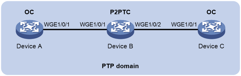
As shown in Figure 5, Device A, Device B, and Device C are in a PTP domain. Configure SMPTE ST 2059-2 PTP in multicast mode as follows for time synchronization:
· Specify the SMPTE ST 2059-2 PTP profile for the devices.
· Configure the multicast PTP transport mode for the devices.
· Specify the OC clock node type for Device A and Device C, and the P2PTC clock node type for Device B. All clock nodes elect a GM through BMC based on their respective default GM attributes.
· Configure the peer delay measurement mechanism (p2p) for Device A and Device C.

Applicable hardware and software versions
The following matrix shows the hardware and software versions to which this configuration example is applicable:
|
Hardware |
Software version |
|
S6812 switch series S6813 switch series |
Release 6615Pxx, Release 6628Pxx |
|
S6550XE-HI switch series |
Release 6008 and later, Release 8106Pxx |
|
S6525XE-HI switch series |
Release 6008 and later, Release 8106Pxx |
|
S5850 switch series |
Not supported |
|
S5560X-EI switch series |
Not supported |
|
S5560X-HI switch series |
Release 6615Pxx, Release 6628Pxx |
|
S5570S-EI switch series |
Not supported |
|
S5500V2-EI switch series |
Not supported |
|
MS4520V2-30F switch |
Not supported |
|
MS4520V2-30C switch MS4520V2-54C switch |
Not supported |
|
MS4520V2-28S switch MS4520V2-24TP switch |
Not supported |
|
ES5500 switch series |
Not supported |
|
S6520X-HI switch series S6520X-EI switch series |
Release 6615Pxx, Release 6628Pxx |
|
S6520X-SI switch series S6520-SI switch series |
Release 6615Pxx, Release 6628Pxx |
|
S5000-EI switch series |
Release 6615Pxx, Release 6628Pxx |
|
MS4600 switch series |
Release 6615Pxx, Release 6628Pxx |
|
S5560S-EI switch series S5560S-SI switch series |
Not supported |
|
S5500V3-24P-SI S5500V3-48P-SI |
Not supported |
|
S5500V3-SI switch series (except the S5500V3-24P-SI and S5500V3-48P-SI) |
Not supported |
|
S5170-EI switch series |
Not supported |
|
S5130S-HI switch series S5130S-EI switch series S5130S-SI switch series S5130S-LI switch series |
Not supported |
|
S5120V2-SI switch series S5120V2-LI switch series |
Not supported |
|
S5120V3-EI switch series |
Not supported |
|
S5120V3-36F-SI S5120V3-28P-HPWR-SI S5120V3-54P-PWR-SI |
Not supported |
|
S5120V3-SI switch series (except the S5120V3-36F-SI, S5120V3-28P-HPWR-SI, and S5120V3-54P-PWR-SI) |
Not supported |
|
S5120V3-LI switch series |
Not supported |
|
S3600V3-EI switch series |
Not supported |
|
S3600V3-SI switch series |
Not supported |
|
S3100V3-EI switch series S3100V3-SI switch series |
Not supported |
|
S5110V2 switch series |
Not supported |
|
S5110V2-SI switch series |
Not supported |
|
S5000V3-EI switch series S5000V5-EI switch series |
Not supported |
|
S5000E-X switch series S5000X-EI switch series |
Not supported |
|
E128C switch E152C switch E500C switch series E500D switch series |
Not supported |
|
MS4320V2 switch series MS4320V3 switch series MS4300V2 switch series MS4320 switch series MS4200 switch series |
Not supported |
|
WS5850-WiNet switch series |
Not supported |
|
WS5820-WiNet switch series WS5810-WiNet switch series |
Not supported |
|
WAS6000 switch series |
Not supported |
|
IE4300-12P-AC switch IE4300-12P-PWR switch IE4300-M switch series (except the IE4300-28P-M) IE4320 switch series (except the IE4320-28P) |
Not supported |
|
IE4300-28P-M switch IE4320-28P switch |
Release 63xx |
Procedures
Configuring Device A
# Specify the SMPTE ST 2059-2 PTP profile.
<DeviceA> system-view
[DeviceA] ptp profile st2059-2
# Specify the OC clock node type.
[DeviceA] ptp mode oc
# Specify a PTP domain.
[DeviceA] ptp domain 0
# Enable PTP globally.
[DeviceA] ptp global enable
# Configure the source IP address for multicast PTP transport.
[DeviceA] ptp source 10.10.10.1
# Specify PTP for obtaining the time.
[DeviceA] clock protocol ptp
# On GigabitEthernet 1/0/1, specify the peer delay measurement mechanism (p2p) and enable PTP.
[DeviceA] interface gigabitethernet 1/0/1
[DeviceA-GigabitEthernet1/0/1] ptp delay-mechanism p2p
[DeviceA-GigabitEthernet1/0/1] ptp enable
[DeviceA-GigabitEthernet1/0/1] quit
Configuring Device B
# Specify the SMPTE ST 2059-2 PTP profile.
<DeviceB> system-view
[DeviceB] ptp profile st2059-2
# Specify the P2PTC clock node type.
[DeviceB] ptp mode p2ptc
# Specify a PTP domain.
[DeviceB] ptp domain 0
# Enable PTP globally.
[DeviceB] ptp global enable
# Configure the source IP address for multicast PTP transport.
[DeviceB] ptp source 10.10.10.2
# Specify PTP for obtaining the time.
[DeviceB] clock protocol ptp
# Enable PTP on GigabitEthernet 1/0/1.
[DeviceB] interface gigabitethernet 1/0/1
[DeviceB-GigabitEthernet1/0/1] ptp enable
[DeviceB-GigabitEthernet1/0/1] quit
# Enable PTP on GigabitEthernet 1/0/2.
[DeviceB] interface gigabitethernet 1/0/2
[DeviceB-GigabitEthernet1/0/2] ptp enable
[DeviceB-GigabitEthernet1/0/2] quit
Configuring Device C
# Specify the SMPTE ST 2059-2 PTP profile.
<DeviceC> system-view
[DeviceC] ptp profile st2059-2
# Specify the OC clock node type.
[DeviceC] ptp mode oc
# Specify a PTP domain.
[DeviceC] ptp domain 0
# Enable PTP globally.
[DeviceC] ptp global enable
# Configure the source IP address for multicast PTP transport.
[DeviceC] ptp source 11.10.10.1
# Specify PTP for obtaining the time.
[DeviceC] clock protocol ptp
# On GigabitEthernet 1/0/1, specify the peer delay measurement mechanism (p2p) and enable PTP.
[DeviceC] interface gigabitethernet 1/0/1
[DeviceC-GigabitEthernet1/0/1] ptp delay-mechanism p2p
[DeviceC-GigabitEthernet1/0/1] ptp enable
[DeviceC-GigabitEthernet1/0/1] quit
Verifying the configuration
|
|
IMPORTANT: · The Lock status field in the output from the display ptp clock command is available only for the S6550XE-HI switch series and S6525XE-HI switch series. · The InstID field in the output from the display ptp interface brief command is available only for the S6550XE-HI switch series and S6525XE-HI switch series. |
When the network topology is stable, perform the following tasks to verify the PTP configuration:
· Use the display ptp clock command to display PTP clock information.
· Use the display ptp interface brief command to display brief information about PTP interfaces.
# Display PTP clock information on Device A.
[DeviceA] display ptp clock
PTP global state : Enabled
PTP profile : SMPTE ST 2059-2
PTP mode : OC
Slave only : No
Lock status : Unlocked
Clock ID : 000FE2-FFFE-FF0000
Clock type : Local
Clock domain : 0
Number of PTP ports : 1
Priority1 : 128
Priority2 : 128
Clock quality :
Class : 248
Accuracy : 254
Offset (log variance) : 65535
Offset from master : 0 (ns)
Mean path delay : 0 (ns)
Steps removed : 0
Local clock time : Sun Jan 15 20:57:29 2019
# Display brief information about PTP interfaces on Device A.
[DeviceA] display ptp interface brief
Name InstID State Delay mechanism Clock step Asymmetry correction
GE1/0/1 0 Master P2P Two 0
# Display PTP clock information on Device B.
[DeviceB] display ptp clock
PTP global state : Enabled
PTP profile : SMPTE ST 2059-2
PTP mode : P2PTC
Slave only : No
Lock status : Unlocked
Clock ID : 000FE2-FFFE-FF0001
Clock type : Local
Clock domain : 0
Number of PTP ports : 2
Priority1 : 128
Priority2 : 128
Clock quality :
Class : 248
Accuracy : 254
Offset (log variance) : 65535
Offset from master : N/A
Mean path delay : N/A
Steps removed : N/A
Local clock time : Sun Jan 15 20:57:29 2019
# Display brief information about PTP interfaces on Device B.
[DeviceB] display ptp interface brief
Name InstID State Delay mechanism Clock step Asymmetry correction
GE1/0/1 0 N/A P2P Two 0
GE1/0/2 0 N/A P2P Two 0
# Display PTP clock information on Device C.
[DeviceC] display ptp clock
PTP global state : Enabled
PTP profile : SMPTE ST 2059-2
PTP mode : OC
Slave only : No
Lock status : Locked
Clock ID : 000FE2-FFFE-FF0002
Clock type : Local
Clock domain : 0
Number of PTP ports : 1
Priority1 : 128
Priority2 : 128
Clock quality :
Class : 248
Accuracy : 254
Offset (log variance) : 65535
Offset from master : 25 (ns)
Mean path delay : 0 (ns)
Steps removed : 2
Local clock time : Sun Jan 15 20:57:29 2019
# Display brief information about PTP interfaces on Device C.
[DeviceC] display ptp interface brief
Name InstID State Delay mechanism Clock step Asymmetry correction
GE1/0/1 0 Slave P2P Two 0
The output shows that Device A is elected as the GM and GigabitEthernet1/0/1 on Device A is the master port.
Configuration files
· Device A:
#
clock protocol ptp
#
ptp profile st2059-2
ptp mode oc
ptp domain 0
ptp global enable
ptp source 10.10.10.1
#
interface GigabitEthernet 1/0/1
ptp delay-mechanism p2p
ptp enable
#
· Device B:
#
clock protocol ptp
#
ptp profile st2059-2
ptp mode p2ptc
ptp domain 0
ptp global enable
ptp source 10.10.10.2
#
interface GigabitEthernet 1/0/1
ptp enable
#
interface GigabitEthernet 1/0/2
ptp enable
#
· Device C:
#
clock protocol ptp
#
ptp profile st2059-2
ptp mode oc
ptp domain 0
ptp global enable
ptp source 11.10.10.1
#
interface GigabitEthernet 1/0/1
ptp delay-mechanism p2p
ptp enable
#
Example: Configuring PTP (SMPTE ST 2059-2, IPv4 UDP transport, unicast transmission)
Network configuration
As shown in Figure 6, configure PTP (SMPTE ST 2059-2, IPv4 UDP transport, unicast transmission) to enable Device A, Device B, Device C, and the base station to synchronize time with the ToD clock source.
· Specify the SMPTE ST 2059-2 PTP profile and unicast IPv4 UDP transport of PTP messages for Device A, Device B, and Device C.
· Assign Device A, Device B, Device C, and the base station to PTP domain 0. Specify the BC clock node type for Device A, Device B, and Device C.
· Connect Device A to the ToD clock source and Device C to the base station.
· Use the default Request_Response delay measurement mechanism on all clock nodes in the PTP domain.

Applicable hardware and software versions
The following matrix shows the hardware and software versions to which this configuration example is applicable:
|
Hardware |
Software version |
|
S6812 switch series S6813 switch series |
Release 6615Pxx, Release 6628Pxx |
|
S6550XE-HI switch series |
Release 6008 and later, Release 8106Pxx |
|
S6525XE-HI switch series |
Release 6008 and later, Release 8106Pxx |
|
S5850 switch series |
Not supported |
|
S5570S-EI switch series |
Not supported |
|
S5560X-EI switch series |
Not supported |
|
S5560X-HI switch series |
Release 6615Pxx, Release 6628Pxx |
|
S5500V2-EI switch series |
Not supported |
|
MS4520V2-30F |
Not supported |
|
MS4520V2-30C MS4520V2-54C |
Not supported |
|
MS4520V2-28S MS4520V2-24TP |
Not supported |
|
ES5500 switch series |
Not supported |
|
S6520X-HI switch series S6520X-EI switch series |
Release 6615Pxx, Release 6628Pxx |
|
S6520X-SI switch series S6520-SI switch series |
Release 6615Pxx, Release 6628Pxx |
|
S5000-EI switch series |
Release 6615Pxx, Release 6628Pxx |
|
MS4600 switch series |
Release 6615Pxx, Release 6628Pxx |
|
S5560S-EI switch series S5560S-SI switch series |
Not supported |
|
S5500V3-24P-SI S5500V3-48P-SI |
Not supported |
|
S5500V3-SI switch series (except the S5500V3-24P-SI and S5500V3-48P-SI) |
Not supported |
|
S5170-EI switch series |
Not supported |
|
S5130S-HI switch series S5130S-EI switch series S5130S-SI switch series S5130S-LI switch series |
Not supported |
|
S5120V2-SI switch series S5120V2-LI switch series |
Not supported |
|
S5120V3-EI switch series |
Not supported |
|
S5120V3-36F-SI S5120V3-28P-HPWR-SI S5120V3-54P-PWR-SI |
Not supported |
|
S5120V3-SI switch series (except the S5120V3-36F-SI, S5120V3-28P-HPWR-SI, and S5120V3-54P-PWR-SI) |
Not supported |
|
S5120V3-LI switch series |
Not supported |
|
S3600V3-EI switch series |
Not supported |
|
S3600V3-SI switch series |
Not supported |
|
S3100V3-EI switch series S3100V3-SI switch series |
Not supported |
|
S5110V2 switch series |
Not supported |
|
S5110V2-SI switch series |
Not supported |
|
S5000V3-EI switch series S5000V5-EI switch series |
Not supported |
|
S5000E-X switch series S5000X-EI switch series |
Not supported |
|
E128C E152C E500C switch series E500D switch series |
Not supported |
|
MS4320V2 switch series MS4320V3 switch series MS4300V2 switch series MS4320 switch series MS4200 switch series |
Not supported |
|
WS5850-WiNet switch series |
Not supported |
|
WS5820-WiNet switch series WS5810-WiNet switch series |
Not supported |
|
WAS6000 switch series |
Not supported |
|
IE4300-12P-AC & IE4300-12P-PWR IE4300-M switch series (except the IE4300-28P-M) IE4320 switch series (except the IE4320-28P) |
Not supported |
|
IE4300-28P-M IE4320-28P |
Not supported |
Procedures
|
|
IMPORTANT: The SMPTE ST 2059-2 PTP profile supports IPv4 UDP transport rather than IEEE 802.3/Ethernet transport of PTP messages. It supports both multicast and unicast transmission of PTP messages. |
|
|
IMPORTANT: The device does not provide ToD interfaces. It can be deployed as Device B or Device C but not Device A. |
Before configuration, assign IP addresses to the interfaces, and make sure the devices can reach each other. (Details not shown.)
Configuring Device A
# Specify the SMPTE ST 2059-2 PTP profile.
<DeviceA> system-view
[DeviceA] ptp profile st2059-2
# Specify the BC clock node type.
[DeviceA] ptp mode bc
# Create a PTP domain.
[DeviceA] ptp domain 0
# Enable PTP globally.
[DeviceA] ptp global enable
# Configure the device to use ToD 0 to receive clock signals and set the receive delay correction to 1000 nanoseconds
[DeviceA] ptp tod0 input delay 1000
# Set priority 1 to 0 for the ToD 0 clock.
[DeviceA] ptp priority clock-source tod0 priority1 0
# On GigabitEthernet 1/0/1, configure the destination IP address for unicast PTP messages and enable PTP. (The SMPTE ST 2059-2 PTP profile transports PTP messages over IPv4 UDP by default.)
[DeviceA] interface gigabitethernet 1/0/1
[DeviceA-GigabitEthernet1/0/1] ptp unicast-destination 10.10.10.2
[DeviceA-GigabitEthernet1/0/1] ptp enable
[DeviceA-GigabitEthernet1/0/1] quit
Configuring Device B
# Specify the SMPTE ST 2059-2 PTP profile.
<DeviceB> system-view
[DeviceB] ptp profile st2059-2
# Specify the BC clock node type.
[DeviceB] ptp mode bc
# Create a PTP domain.
[DeviceB] ptp domain 0
# Enable PTP globally.
[DeviceB] ptp global enable
# Specify PTP for obtaining the time
[DeviceA] clock protocol ptp
# On GigabitEthernet 1/0/1, configure the destination IP address for unicast PTP messages and enable PTP. (The SMPTE ST 2059-2 PTP profile transports PTP messages over IPv4 UDP by default.)
[DeviceB] interface gigabitethernet 1/0/1
[DeviceB-GigabitEthernet1/0/1] ptp unicast-destination 10.10.10.1
[DeviceB-GigabitEthernet1/0/1] ptp enable
[DeviceB-GigabitEthernet1/0/1] quit
# On GigabitEthernet 1/0/2, configure the destination IP address for unicast PTP messages and enable PTP. (The SMPTE ST 2059-2 PTP profile transports PTP messages over IPv4 UDP by default.)
[DeviceB] interface gigabitethernet 1/0/2
[DeviceB-GigabitEthernet1/0/2] ptp unicast-destination 11.10.10.1
[DeviceB-GigabitEthernet1/0/2] ptp enable
[DeviceB-GigabitEthernet1/0/2] quit
Configuring Device C
# Specify the SMPTE ST 2059-2 PTP profile.
<DeviceC> system-view
[DeviceC] ptp profile st2059-2
# Specify the BC clock node type.
[DeviceC] ptp mode bc
# Create a PTP domain.
[DeviceC] ptp domain 0
# Enable PTP globally.
[DeviceC] ptp global enable
# Specify PTP for obtaining the time
[DeviceA] clock protocol ptp
# On GigabitEthernet 1/0/1, configure the destination IP address for unicast PTP messages and enable PTP.
[DeviceC] interface gigabitethernet 1/0/1
[DeviceC-GigabitEthernet1/0/1] ptp unicast-destination 11.10.10.2
[DeviceC-GigabitEthernet1/0/1] ptp enable
[DeviceC-GigabitEthernet1/0/1] quit
# On GigabitEthernet1/0/2, configure the destination IP address for unicast PTP messages and enable PTP. (The SMPTE ST 2059-2 PTP profile transports PTP messages over IPv4 UDP by default.)
[DeviceC] interface gigabitethernet 1/0/2
[DeviceC-GigabitEthernet1/0/2] ptp unicast-destination 12.10.10.1
[DeviceC-GigabitEthernet1/0/2] ptp enable
[DeviceC-GigabitEthernet1/0/2] quit
Configuring the base station
# Specify PTP domain 0.
# Specify IPv4 UDP transport of PTP messages.
# Set the destination IP address of unicast PTP messages to 12.10.10.2.
# Specify the Request_Response delay measurement mechanism.
For more information, see the configuration guide for the base station.
Verifying the configuration
|
|
IMPORTANT: · The Lock status field in the output from the display ptp clock command is available only for the S6550XE-HI switch series and S6525XE-HI switch series. · The InstID field in the output from the display ptp interface brief command is available only for the S6550XE-HI switch series and S6525XE-HI switch series. |
When the network is stable, perform the following tasks to verify the PTP configuration:
· Use the display ptp clock command to display PTP clock information.
· Use the display ptp interface brief command to display brief PTP running information.
# Display PTP clock information on Device A.
[DeviceA] display ptp clock
PTP global state : Enabled
PTP profile : SMPTE ST 2059-2
PTP mode : BC
Slave only : No
Lock status : Unlocked
Clock ID : 000FE2-FFFE-FF0000
Clock type : ToD0
ToD direction : In
ToD delay time : 1000 (ns)
Clock domain : 0
Number of PTP ports : 1
Priority1 : 0
Priority2 : 128
Clock quality :
Class : 6
Accuracy : 32
Offset (log variance) : 65535
Offset from master : 0 (ns)
Mean path delay : 0 (ns)
Steps removed : 0
Local clock time : Sun Jan 15 20:57:29 2019
# Display brief PTP running information on Device A.
[DeviceA] display ptp interface brief
Name InstID State Delay mechanism Clock step Asymmetry correction
GE1/0/1 0 Master E2E Two 0
# Display PTP clock information on Device B.
[DeviceA] display ptp clock
PTP global state : Enabled
PTP profile : SMPTE ST 2059-2
PTP mode : BC
Slave only : No
Lock status : Locked
Clock ID : 000FE2-FFFE-FF0001
Clock type : ToD0
ToD direction : In
ToD delay time : 1000 (ns)
Clock domain : 0
Number of PTP ports : 1
Priority1 : 0
Priority2 : 128
Clock quality :
Class : 6
Accuracy : 32
Offset (log variance) : 65535
Offset from master : 12 (ns)
Mean path delay : 323 (ns)
Steps removed : 1
Local clock time : Sun Jan 15 20:57:29 2019
# Display brief PTP running information on Device B.
[DeviceB] display ptp interface brief
Name InstID State Delay mechanism Clock step Asymmetry correction
GE1/0/1 0 Slave E2E Two 0
GE1/0/2 0 Master E2E Two 0
# Display PTP clock information on Device C.
[DeviceC] display ptp clock
PTP global state : Enabled
PTP profile : SMPTE ST 2059-2
PTP mode : BC
Slave only : No
Lock status : Locked
Clock ID : 000FE2-FFFE-FF0002
Clock type : Local
Clock domain : 0
Number of PTP ports : 2
Priority1 : 128
Priority2 : 128
Clock quality :
Class : 248
Accuracy : 254
Offset (log variance) : 65535
Offset from master : 25 (ns)
Mean path delay : 323 (ns)
Steps removed : 2
Local clock time : Sun Jan 15 20:57:29 2019
# Display brief PTP running information on Device C.
[DeviceC] display ptp interface brief
Name InstID State Delay mechanism Clock step Asymmetry correction
GE1/0/1 0 Slave E2E Two 0
GE1/0/2 0 Master E2E Two 0
Configuration files
· Device A
#
clock protocol ptp
#
ptp profile st2059-2
ptp mode bc
ptp domain 0
ptp global enable
ptp tod0 input delay 1000
ptp priority clock-source tod0 priority1 0
#
interface GigabitEthernet 1/0/1
ptp unicast-destination 10.10.10.2
ptp enable
#
· Device B
#
clock protocol ptp
#
ptp profile st2059-2
ptp mode bc
ptp domain 0
ptp global enable
#
interface GigabitEthernet 1/0/1
ptp unicast-destination 10.10.10.1
ptp enable
#
interface GigabitEthernet 1/0/2
ptp enable
#
· Device C
#
clock protocol ptp
#
ptp profile st2059-2
ptp mode bc
ptp domain 0
ptp global enable
#
interface GigabitEthernet 1/0/1
ptp unicast-destination 11.10.10.2
ptp enable
#
interface GigabitEthernet 1/0/2
ptp unicast-destination 12.10.10.1
ptp enable
#
