- Table of Contents
-
- H3C Fixed Port Campus Switches Configuration Examples-6W104
- 00-Applicable hardware and software versions
- 01-Login Management Configuration Examples
- 02-RBAC Configuration Examples
- 03-Software Upgrade Examples
- 04-ISSU Configuration Examples
- 05-Software Patching Examples
- 06-Ethernet Link Aggregation Configuration Examples
- 07-Port Isolation Configuration Examples
- 08-Spanning Tree Configuration Examples
- 09-VLAN Configuration Examples
- 10-VLAN Tagging Configuration Examples
- 11-DHCP Snooping Configuration Examples
- 12-Cross-Subnet Dynamic IP Address Allocation Configuration Examples
- 13-IPv6 over IPv4 Tunneling with OSPFv3 Configuration Examples
- 14-IPv6 over IPv4 GRE Tunnel Configuration Examples
- 15-GRE with OSPF Configuration Examples
- 16-OSPF Configuration Examples
- 17-IS-IS Configuration Examples
- 18-BGP Configuration Examples
- 19-Policy-Based Routing Configuration Examples
- 20-OSPFv3 Configuration Examples
- 21-IPv6 IS-IS Configuration Examples
- 22-Routing Policy Configuration Examples
- 23-IGMP Snooping Configuration Examples
- 24-IGMP Configuration Examples
- 25-MLD Snooping Configuration Examples
- 26-IPv6 Multicast VLAN Configuration Examples
- 27-ACL Configuration Examples
- 28-Traffic Policing Configuration Examples
- 29-GTS and Rate Limiting Configuration Examples
- 30-Traffic Filtering Configuration Examples
- 31-AAA Configuration Examples
- 32-Port Security Configuration Examples
- 33-Portal Configuration Examples
- 34-SSH Configuration Examples
- 35-IP Source Guard Configuration Examples
- 36-Ethernet OAM Configuration Examples
- 37-CFD Configuration Examples
- 38-DLDP Configuration Examples
- 39-VRRP Configuration Examples
- 40-BFD Configuration Examples
- 41-NTP Configuration Examples
- 42-SNMP Configuration Examples
- 43-NQA Configuration Examples
- 44-Mirroring Configuration Examples
- 45-sFlow Configuration Examples
- 46-OpenFlow Configuration Examples
- 47-MAC Address Table Configuration Examples
- 48-Static Multicast MAC Address Entry Configuration Examples
- 49-IP Unnumbered Configuration Examples
- 50-MVRP Configuration Examples
- 51-MCE Configuration Examples
- 52-Attack Protection Configuration Examples
- 53-Smart Link Configuration Examples
- 54-RRPP Configuration Examples
- 55-BGP Route Selection Configuration Examples
- 56-IS-IS Route Summarization Configuration Examples
- 57-VXLAN Configuration Examples
- 58-DRNI Configuration Examples
- 59-IRF 3.1 Configuration Examples
- 60-PTP Configuration Examples
- 61-S-MLAG Configuration Examples
- 62-Puppet Configuration Examples
- 63-802.1X Configuration Examples
- 64-MAC Authentication Configuration Examples
- 65-ISATAP Tunnel and 6to4 Tunnel Configuration Examples
- 66-BIDIR-PIM Configuration Examples
- 67-Congestion Avoidance and Queue Scheduling Configuration Examples
- 68-Basic MPLS Configuration Examples
- 69-MPLS L3VPN Configuration Examples
- 70-MPLS OAM Configuration Examples
- 71-EVPN-DCI over an MPLS L3VPN Network Configuration Examples
- 72-DRNI and EVPN Configuration Examples
- 73-Multicast VPN Configuration Examples
- 74-MPLS TE Configuration Examples
- 75-Control Plane-Based QoS Policy Configuration Examples
- 76-Priority Mapping and Queue Scheduling Configuration Examples
- 77-ARP Attack Protection Configuration Examples
- 78-IRF Software Upgrade Configuration Examples
- 79-IRF Member Replacement Configuration Examples
- 80-Layer 3 Multicast on Multicast Source-Side DR System Configuration Examples
- 81-EVPN Multicast Configuration Examples
- Related Documents
-
| Title | Size | Download |
|---|---|---|
| 14-IPv6 over IPv4 GRE Tunnel Configuration Examples | 89.44 KB |
Introduction
This document provides IPv6 over IPv4 GRE tunnel configuration examples.
Prerequisites
The configuration examples in this document were created and verified in a lab environment, and all the devices were started with the factory default configuration. When you are working on a live network, make sure you understand the potential impact of every command on your network.
This document assumes that you have basic knowledge of GRE.
Example: Configuring an IPv6 over IPv4 GRE tunnel
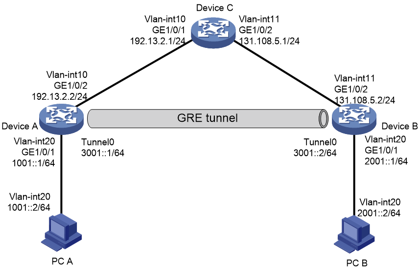
Network configuration
As shown in Figure 1, Device A, Device B, and Device C are all on an IPv4 network. Dual stack devices Device A and Device B each connect to an IPv6 host.
Configure a GRE/IPv4 tunnel between Device A and Device B, so PC A and PC B can communicate with each other over the IPv4 network.
Analysis
To meet the network requirements, perform the following tasks:
· To enable the IPv6 hosts to communicate over the IPv4 network, specify the GRE tunnel mode as GRE/IPv4 and configure IPv6 addresses for the tunnel interfaces.
· To transmit packets between PC A and PC B through the GRE tunnel, configure a route reaching the destination network through the tunnel interface on Device A and Device B. You can configure the routes by using either of the following methods:
¡ Configure static routes, using the peer tunnel interface as the next hop or using the local tunnel interface as the outgoing interface.
¡ Enable a dynamic routing protocol on both the tunnel interfaces and the Layer 3 interfaces connected to PC A and PC B.
· For both ends of the GRE tunnel to reach each other, configure a static route reaching the remote end on Device A and Device B.
Applicable hardware and software versions
The following matrix shows the hardware and software versions to which this configuration example is applicable:
|
Hardware |
Software version |
|
S6812 switch series S6813 switch series |
Release 6615Pxx, Release 6628Pxx |
|
S6550XE-HI switch series |
Release 6008 and later, Release 8106Pxx |
|
S6525XE-HI switch series |
Release 6008 and later, Release 8106Pxx |
|
S5850 switch series |
Release 8005 and later |
|
S5570S-EI switch |
Not supported |
|
S5560X-EI switch series |
Release 63xx, Release 65xx, Release 6615Pxx, Release 6628Pxx |
|
S5560X-HI switch series |
Release 63xx, Release 65xx, Release 6615Pxx, Release 6628Pxx |
|
S5500V2-EI switch series |
Release 63xx, Release 65xx, Release 6615Pxx, Release 6628Pxx |
|
MS4520V2-30F switch |
Release 63xx, Release 65xx, Release 6615Pxx, Release 6628Pxx |
|
MS4520V2-30C switch MS4520V2-54C switch |
Release 65xx, Release 6615Pxx, Release 6628Pxx |
|
MS4520V2-28S switch MS4520V2-24TP switch |
Release 63xx |
|
S6520X-HI switch series S6520X-EI switch series |
Release 63xx, Release 65xx, Release 6615Pxx, Release 6628Pxx |
|
S6520X-SI switch series S6520-SI switch series |
Release 63xx, Release 65xx, Release 6615Pxx, Release 6628Pxx |
|
S5000-EI switch series |
Release 63xx, Release 65xx, Release 6615Pxx, Release 6628Pxx |
|
MS4600 switch series |
Release 63xx, Release 65xx, Release 6615Pxx, Release 6628Pxx |
|
ES5500 switch series |
Release 63xx, Release 65xx, Release 6615Pxx, Release 6628Pxx |
|
S5560S-EI switch series S5560S-SI switch series |
Release 63xx |
|
S5500V3-24P-SI switch S5500V3-48P-SI switch |
Release 63xx |
|
S5500V3-SI switch series (except the S5500V3-24P-SI and S5500V3-48P-SI switches) |
Not supported |
|
S5170-EI switch series |
Not supported |
|
S5130S-HI switch series S5130S-EI switch series S5130S-SI switch series S5130S-LI switch series |
Not supported |
|
S5120V2-SI switch series S5120V2-LI switch series |
Not supported |
|
S5120V3-EI switch series |
Not supported |
|
S5120V3-36F-SI switch S5120V3-28P-HPWR-SI switch S5120V3-54P-PWR-SI switch |
Not supported |
|
S5120V3-SI switch series (except the S5120V3-36F-SI, S5120V3-28P-HPWR-SI, and S5120V3-54P-PWR-SI switches) |
Not supported |
|
S5120V3-LI switch series |
Not supported |
|
S3600V3-EI switch series |
Not supported |
|
S3600V3-SI switch series |
Not supported |
|
S3100V3-EI switch series S3100V3-SI switch series |
Not supported |
|
S5110V2 switch series |
Not supported |
|
S5110V2-SI switch series |
Not supported |
|
S5000V3-EI switch series S5000V5-EI switch series |
Not supported |
|
S5000E-X switch series S5000X-EI switch series |
Not supported |
|
E128C switch E152C switch E500C switch series E500D switch series |
Not supported |
|
MS4320V2 switch series MS4320V3 switch series MS4300V2 switch series MS4320 switch series MS4200 switch series |
Not supported |
|
WS5850-WiNet switch series |
Release 63xx |
|
WS5820-WiNet switch series WS5810-WiNet switch series |
Not supported |
|
WAS6000 switch series |
Not supported |
|
IE4300-12P-AC switch IE4300-12P-P WR switch IE4300-M switch series IE4320 switch series |
Not supported |
Restrictions and guidelines
You must configure the tunnel source address and destination address at both ends of the tunnel. The tunnel source or destination address at one end must be the tunnel destination or source address at the other end.
Procedures
Configuring Device A
# Configure VLAN-interface 20.
<DeviceA> system-view
[DeviceA] vlan 20
[DeviceA-vlan20] port GigabitEthernet 1/0/1
[DeviceA-vlan20] quit
[DeviceA] interface vlan-interface 20
[DeviceA-vlan-interface20] ipv6 address 1001::1 64
[DeviceA-vlan-interface20] quit
# Configure other interfaces in the same way VLAN-interface 20 is configured. (Details not shown.)
# Create service loopback group 1 and specify tunnel services for the group, and then add GigabitEthernet 1/0/3 to the group. (This step is required for the S6550XE-HI, S6525XE-HI, and S5850 switch series to receive and send tunnel packets.)
[DeviceA] service-loopback group 1 type tunnel
[DeviceA] interface gigabitethernet 1/0/3
[DeviceA-GigabitEthernet1/0/3] port service-loopback group 1
[DeviceA-GigabitEthernet1/0/3] quit
# Create a tunnel interface named Tunnel 0, and specify the tunnel mode as GRE/IPv4.
[DeviceA] interface tunnel 0 mode gre
# Configure an IPv6 address for tunnel interface Tunnel 0.
[DeviceA-Tunnel0] ipv6 address 3001::1 64
# Configure the source address of tunnel interface Tunnel 0 as the IP address of VLAN-interface 10.
[DeviceA-Tunnel0] source 192.13.2.2
# Configure the destination address of tunnel interface Tunnel 0 as the IP address of VLAN-interface 11 on Device B.
[DeviceA-Tunnel0] destination 131.108.5.2
[DeviceA-Tunnel0] quit
# Configure a static route reaching PC B through tunnel interface Tunnel 0.
[DeviceA] ipv6 route-static 2001:: 64 tunnel 0
# Configure a static route reaching the remote end of the GRE tunnel.
[DeviceA] ip route-static 131.108.5.2 255.255.255.0 192.13.2.1
Configuring Device B
# Configure VLAN-interface 20.
<DeviceB> system-view
[DeviceB] vlan 20
[DeviceB-vlan20] port GigabitEthernet 1/0/1
[DeviceB] interface vlan-interface 20
[DeviceB-Vlan-interface20] ipv6 address 2001::1 64
[DeviceB-Vlan-interface20] quit
# Configure other interfaces in the same way VLAN-interface 20 is configured. (Details not shown.)
# Create service loopback group 1 and specify tunnel services for the group, and then add GigabitEthernet 1/0/3 to the group. (This step is required for the S6550XE-HI, S6525XE-HI, and S5850 switch series to receive and send tunnel packets.)
[DeviceB] service-loopback group 1 type tunnel
[DeviceB] interface gigabitethernet 1/0/3
[DeviceB-GigabitEthernet1/0/3] port service-loopback group 1
[DeviceB-GigabitEthernet1/0/3] quit
# Create a tunnel interface named Tunnel 0, and specify the tunnel mode as GRE/IPv4.
[DeviceB] interface tunnel 0 mode gre
# Configure an IPv6 address for tunnel interface Tunnel 0.
[DeviceB-Tunnel0] ipv6 address 3001::2 64
# Configure the source address of tunnel interface Tunnel 0 as the IP address of VLAN-interface 11.
[DeviceB-Tunnel0] source 131.108.5.2
# Configure the destination address of tunnel interface Tunnel 0 as the IP address of VLAN-interface 10 on Device A.
[DeviceB-Tunnel0] destination 192.13.2.2
[DeviceB-Tunnel0] quit
# Configure a static route reaching PC A through tunnel interface Tunnel 0.
[DeviceB] ipv6 route-static 1001:: 64 Tunnel 0
# Configure a static route reaching the remote end of the GRE tunnel.
[DeviceB] ip route-static 192.13.2.2 255.255.255.0 131.108.5.1
Configuring Device C
# Configure VLAN-interface 10.
<DeviceC> system-view
[DeviceC] vlan 10
[DeviceC-vlan10] port GigabitEthernet 1/0/1
[DeviceC-vlan10] quit
[DeviceC] interface Vlan-interface 10
[DeviceC-Vlan-interface10] ip address 192.13.2.1 24
[DeviceC-Vlan-interface10] quit
# Configure VLAN-interface 11.
[DeviceC] vlan 11
[DeviceC-vlan11] port GigabitEthernet 1/0/2
[DeviceC-vlan11] quit
[DeviceC] interface vlan-interface 11
[DeviceC-Vlan-interface11] ip address 131.108.5.1 24
[DeviceC-Vlan-interface11] quit
Verifying the configuration
# Verify that PC A and PC B can ping each other successfully. This example uses PC A to ping PC B.
C:\>ping6 2001::2
Pinging 2001::2
from 1001::1 with 32 bytes of data:
Reply from 2001::2: bytes=32 time<1ms
Reply from 2001::2: bytes=32 time<1ms
Reply from 2001::2: bytes=32 time<1ms
Reply from 2001::2: bytes=32 time<1ms
Ping statistics for 2001::2:
Packets: Sent = 4, Received = 4, Lost = 0 (0% loss),
Approximate round trip times in milli-seconds:
Minimum = 0ms, Maximum = 0ms, Average = 0ms
Configuration files
|
|
IMPORTANT: Support for the port link-mode bridge command depends on the device model. |
· Device A:
#
service-loopback group 1 type tunnel
#
vlan 10
#
vlan 20
#
interface Vlan-interface10
ip address 192.13.2.2 255.255.255.0
#
interface Vlan-interface20
ipv6 address 1001::1/64
#
interface GigabitEthernet1/0/1
port link-mode bridge
port access vlan 20
#
interface GigabitEthernet1/0/2
port link-mode bridge
port access vlan 10
#
interface GigabitEthernet1/0/3
port link-mode bridge
port service-loopback group 1
#
interface Tunnel0 mode gre
ipv6 address 3001::1/64
source 192.13.2.2
destination 131.108.5.2
#
ip route-static 131.108.5.2 255.255.255.0 192.13.2.1
#
ipv6 route-static 2001:: 64 Tunnel 0
#
· Device B:
#
service-loopback group 1 type tunnel
#
vlan 11
#
vlan 20
#
interface Vlan-interface11
ip address 131.108.5.2 255.255.255.0
#
interface Vlan-interface20
ipv6 address 2001::1/64
#
interface GigabitEthernet1/0/1
port link-mode bridge
port access vlan 20
#
interface GigabitEthernet1/0/2
port link-mode bridge
port access vlan 11
#
interface GigabitEthernet1/0/3
port link-mode bridge
port service-loopback group 1
#
interface Tunnel0 mode gre
ipv6 address 3001::2/64
source 131.108.5.2
destination 192.13.2.2
#
ip route-static 192.13.2.2 255.255.255.0 131.108.5.1
#
ipv6 route-static 1001:: 64 Tunnel 0
#
· Device C:
#
vlan 10 to 11
#
interface Vlan-interface10
ip address 192.13.2.1 255.255.255.0
#
interface Vlan-interface11
ip address 131.108.5.1 255.255.255.0
#
interface GigabitEthernet1/0/1
port link-mode bridge
port access vlan 10
#
interface GigabitEthernet1/0/2
port link-mode bridge
port access vlan 11
#
