- Table of Contents
-
- H3C Fixed Port Campus Switches Configuration Examples-6W104
- 00-Applicable hardware and software versions
- 01-Login Management Configuration Examples
- 02-RBAC Configuration Examples
- 03-Software Upgrade Examples
- 04-ISSU Configuration Examples
- 05-Software Patching Examples
- 06-Ethernet Link Aggregation Configuration Examples
- 07-Port Isolation Configuration Examples
- 08-Spanning Tree Configuration Examples
- 09-VLAN Configuration Examples
- 10-VLAN Tagging Configuration Examples
- 11-DHCP Snooping Configuration Examples
- 12-Cross-Subnet Dynamic IP Address Allocation Configuration Examples
- 13-IPv6 over IPv4 Tunneling with OSPFv3 Configuration Examples
- 14-IPv6 over IPv4 GRE Tunnel Configuration Examples
- 15-GRE with OSPF Configuration Examples
- 16-OSPF Configuration Examples
- 17-IS-IS Configuration Examples
- 18-BGP Configuration Examples
- 19-Policy-Based Routing Configuration Examples
- 20-OSPFv3 Configuration Examples
- 21-IPv6 IS-IS Configuration Examples
- 22-Routing Policy Configuration Examples
- 23-IGMP Snooping Configuration Examples
- 24-IGMP Configuration Examples
- 25-MLD Snooping Configuration Examples
- 26-IPv6 Multicast VLAN Configuration Examples
- 27-ACL Configuration Examples
- 28-Traffic Policing Configuration Examples
- 29-GTS and Rate Limiting Configuration Examples
- 30-Traffic Filtering Configuration Examples
- 31-AAA Configuration Examples
- 32-Port Security Configuration Examples
- 33-Portal Configuration Examples
- 34-SSH Configuration Examples
- 35-IP Source Guard Configuration Examples
- 36-Ethernet OAM Configuration Examples
- 37-CFD Configuration Examples
- 38-DLDP Configuration Examples
- 39-VRRP Configuration Examples
- 40-BFD Configuration Examples
- 41-NTP Configuration Examples
- 42-SNMP Configuration Examples
- 43-NQA Configuration Examples
- 44-Mirroring Configuration Examples
- 45-sFlow Configuration Examples
- 46-OpenFlow Configuration Examples
- 47-MAC Address Table Configuration Examples
- 48-Static Multicast MAC Address Entry Configuration Examples
- 49-IP Unnumbered Configuration Examples
- 50-MVRP Configuration Examples
- 51-MCE Configuration Examples
- 52-Attack Protection Configuration Examples
- 53-Smart Link Configuration Examples
- 54-RRPP Configuration Examples
- 55-BGP Route Selection Configuration Examples
- 56-IS-IS Route Summarization Configuration Examples
- 57-VXLAN Configuration Examples
- 58-DRNI Configuration Examples
- 59-IRF 3.1 Configuration Examples
- 60-PTP Configuration Examples
- 61-S-MLAG Configuration Examples
- 62-Puppet Configuration Examples
- 63-802.1X Configuration Examples
- 64-MAC Authentication Configuration Examples
- 65-ISATAP Tunnel and 6to4 Tunnel Configuration Examples
- 66-BIDIR-PIM Configuration Examples
- 67-Congestion Avoidance and Queue Scheduling Configuration Examples
- 68-Basic MPLS Configuration Examples
- 69-MPLS L3VPN Configuration Examples
- 70-MPLS OAM Configuration Examples
- 71-EVPN-DCI over an MPLS L3VPN Network Configuration Examples
- 72-DRNI and EVPN Configuration Examples
- 73-Multicast VPN Configuration Examples
- 74-MPLS TE Configuration Examples
- 75-Control Plane-Based QoS Policy Configuration Examples
- 76-Priority Mapping and Queue Scheduling Configuration Examples
- 77-ARP Attack Protection Configuration Examples
- 78-IRF Software Upgrade Configuration Examples
- 79-IRF Member Replacement Configuration Examples
- 80-Layer 3 Multicast on Multicast Source-Side DR System Configuration Examples
- 81-EVPN Multicast Configuration Examples
- Related Documents
-
| Title | Size | Download |
|---|---|---|
| 70-MPLS OAM Configuration Examples | 161.24 KB |
Contents
Example: Configuring BFD for an LSP
Applicable hardware and software versions
Example: Configuring SBFD for an LSP
Applicable hardware and software versions
Introduction
This document provides MPLS Operation, Administration, and Maintenance (OAM) configuration examples.
MPLS OAM provides the following fault management tools for LSPs:
· MPLS data plane connectivity verification.
· MPLS data plane and control plane consistency verification.
· Failure detection and locating.
Prerequisites
The configuration examples in this document were created and verified in a lab environment, and all the devices were started with the factory default configuration. When you are working on a live network, make sure you understand the potential impact of every command on your network.
This document assumes that you have basic knowledge of MPLS OAM.
Example: Configuring BFD for an LSP
Network configuration
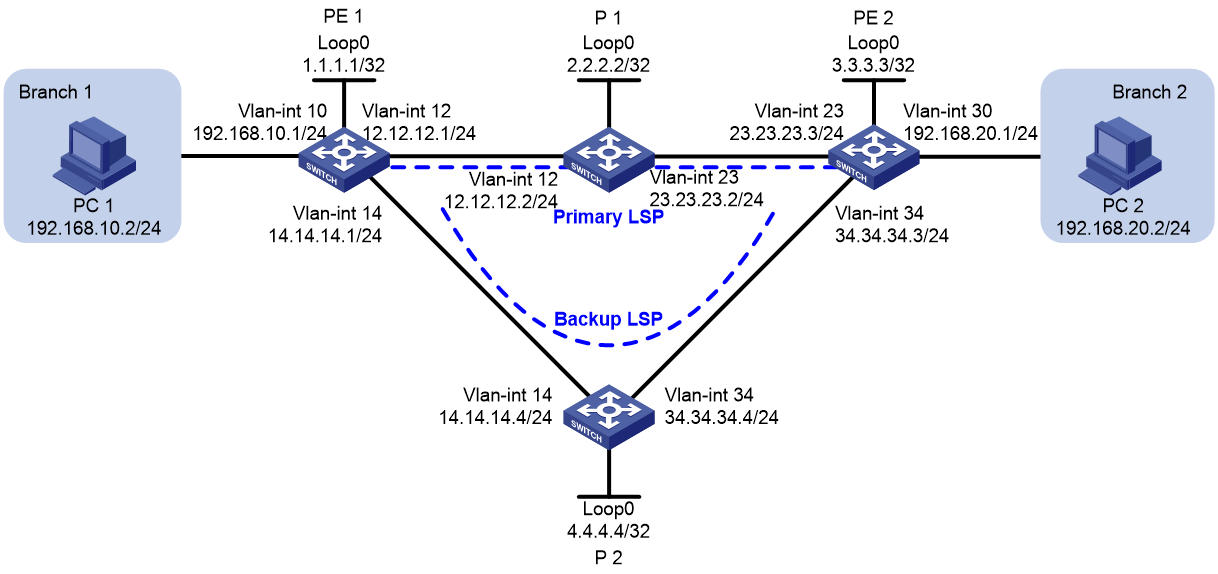
As shown in Figure 1, a company has two branches that are connected to the MPLS backbone. It requires the MPLS backbone to establish LSPs for communication between the branches, and to provide high availability services for uninterrupted business between the branches.
To meet the requirements:
· Establish LSPs by using LDP.
· Configure OSPF FRR on the MPLS backbone so LDP can establish a primary LSP and a backup LSP.
· Configure BFD for the primary LSP. When the primary LSP fails, BFD can quickly detect the failure and notify LDP of the failure, so LDP can immediately switch traffic to the backup LSP.
Applicable hardware and software versions
The following matrix shows the hardware and software versions to which this configuration example is applicable:
|
Hardware |
Software version |
|
S6812 switch series S6813 switch series |
Release 6615Pxx, Release 6628Pxx |
|
S6550XE-HI switch series |
Not supported |
|
S6525XE-HI switch series |
Not supported |
|
S5850 switch series |
Not supported |
|
S5560X-EI switch series |
Release 65xx, Release 6615Pxx, Release 6628Pxx |
|
S5560X-HI switch series |
Release 65xx, Release 6615Pxx, Release 6628Pxx |
|
S5500V2-EI switch series |
Release 65xx, Release 6615Pxx, Release 6628Pxx |
|
ES5500 switch series |
Release 65xx, Release 6615Pxx, Release 6628Pxx |
|
MS4520V2-30F switch MS4520V2-30C switch MS4520V2-54C switch |
Release 65xx, Release 6615Pxx, Release 6628Pxx |
|
S6520X-HI switch series S6520X-EI switch series |
Release 65xx, Release 6615Pxx, Release 6628Pxx |
|
S6520X-SI switch series S6520-SI switch series |
Release 65xx, Release 6615Pxx, Release 6628Pxx |
|
S5000-EI switch series |
Release 65xx, Release 6615Pxx, Release 6628Pxx |
|
MS4600 switch series |
Release 65xx, Release 6615Pxx, Release 6628Pxx |
Restrictions and guidelines
Before configuration, disable the spanning tree feature globally or map each VLAN to an MSTI.
Procedures
1. Configure IP addresses for interfaces:
# On PE 1, configure IP addresses and masks for interfaces, including the loopback interface, as shown in Figure 1.
<PE1> system-view
[PE1] vlan 10
[PE1-vlan10] port gigabitethernet 1/0/3
[PE1-vlan10] quit
[PE1] interface vlan-interface 10
[PE1-Vlan-interface10] ip address 192.168.10.1 24
[PE1] vlan 12
[PE1-vlan12] port gigabitethernet 1/0/1
[PE1-vlan12] quit
[PE1] interface vlan-interface 12
[PE1-Vlan-interface12] ip address 12.12.12.1 24
[PE1-Vlan-interface12] quit
[PE1] vlan 14
[PE1-vlan14] port gigabitethernet 1/0/2
[PE1-vlan14] quit
[PE1] interface vlan-interface 14
[PE1-Vlan-interface14] ip address 14.14.14.1 24
[PE1-Vlan-interface14] quit
[PE1] interface loopback 0
[PE1-LoopBack0] ip address 1.1.1.1 32
[PE1-LoopBack0] quit
# Configure other devices in the same way that PE 1 is configured. (Details not shown.)
2. Configure OSPF to ensure IP connectivity within the MPLS backbone, and enable OSPF FRR:
# Configure PE 1.
[PE1] ospf
[PE1-ospf-1] area 0
[PE1-ospf-1-area-0.0.0.0] network 1.1.1.1 0.0.0.0
[PE1-ospf-1-area-0.0.0.0] network 12.12.12.0 0.0.0.255
[PE1-ospf-1-area-0.0.0.0] network 14.14.14.0 0.0.0.255
[PE1-ospf-1-area-0.0.0.0] network 192.168.10.0 0.0.0.255
[PE1-ospf-1-area-0.0.0.0] quit
[PE1-ospf-1] fast-reroute lfa
[PE1-ospf-1] quit
# Configure P 1.
[P1] ospf
[P1-ospf-1] area 0
[P1-ospf-1-area-0.0.0.0] network 2.2.2.2 0.0.0.0
[P1-ospf-1-area-0.0.0.0] network 12.12.12.0 0.0.0.255
[P1-ospf-1-area-0.0.0.0] network 23.23.23.0 0.0.0.255
[P1-ospf-1-area-0.0.0.0] quit
[P1-ospf-1] quit
# Configure PE 2.
[PE2] ospf
[PE2-ospf-1] area 0
[PE2-ospf-1-area-0.0.0.0] network 3.3.3.3 0.0.0.0
[PE2-ospf-1-area-0.0.0.0] network 23.23.23.0 0.0.0.255
[PE2-ospf-1-area-0.0.0.0] network 34.34.34..0 0.0.0.255
[PE2-ospf-1-area-0.0.0.0] network 192.168.20.0 0.0.0.255
[PE2-ospf-1-area-0.0.0.0] quit
[PE2-ospf-1] fast-reroute lfa
[PE2-ospf-1] quit
# Configure P 2.
[P2] ospf
[P2-ospf-1] area 0
[P2-ospf-1-area-0.0.0.0] network 4.4.4.4 0.0.0.0
[P2-ospf-1-area-0.0.0.0] network 14.14.14.0 0.0.0.255
[P2-ospf-1-area-0.0.0.0] network 34.34.34.0 0.0.0.255
[P2-ospf-1-area-0.0.0.0] quit
[P2-ospf-1] quit
# On P 2, set the OSPF cost to 10 for VLAN-interface 14 and VLAN-interface 34. This setting ensures that the backup LSP has a larger OSPF cost than the primary LSP.
[P2] interface vlan-interface 14
[P2-Vlan-interface14] ospf cost 10
[P2-Vlan-interface14] quit
[P2] interface vlan-interface 34
[P2-Vlan-interface34] ospf cost 10
[P2-Vlan-interface34] quit
3. Configure basic MPLS and MPLS LDP:
# Configure PE 1.
[PE1] mpls lsr-id 1.1.1.1
[PE1] mpls ldp
[PE1-ldp] quit
[PE1] interface vlan-interface 12
[PE1-Vlan-interface12] mpls enable
[PE1-Vlan-interface12] mpls ldp enable
[PE1-Vlan-interface12] quit
[PE1] interface vlan-interface 14
[PE1-Vlan-interface14] mpls enable
[PE1-Vlan-interface14] mpls ldp enable
[PE1-Vlan-interface14] quit
# Configure P 1.
[P1] mpls lsr-id 2.2.2.2
[P1] mpls ldp
[P1-ldp] quit
[P1] interface vlan-interface 12
[P1-Vlan-interface12] mpls enable
[P1-Vlan-interface12] mpls ldp enable
[P1-Vlan-interface12] quit
[P1] interface vlan-interface 23
[P1-Vlan-interface23] mpls enable
[P1-Vlan-interface23] mpls ldp enable
[P1-Vlan-interface23] quit
# Configure PE 2.
[PE2] mpls lsr-id 3.3.3.3
[PE2] mpls ldp
[PE2-ldp] quit
[PE2] interface vlan-interface 23
[PE2-Vlan-interface23] mpls enable
[PE2-Vlan-interface23] mpls ldp enable
[PE2-Vlan-interface23] quit
[PE2] interface vlan-interface 34
[PE2-Vlan-interface34] mpls enable
[PE2-Vlan-interface34] mpls ldp enable
[PE2-Vlan-interface34] quit
# Configure P 2.
[P2] mpls lsr-id 4.4.4.4
[P2] mpls ldp
[P2-ldp] quit
[P2] interface vlan-interface 14
[P2-Vlan-interface14] mpls enable
[P2-Vlan-interface14] mpls ldp enable
[P2-Vlan-interface14] quit
[P2] interface vlan-interface 34
[P2-Vlan-interface34] mpls enable
[P2-Vlan-interface34] mpls ldp enable
[P2-Vlan-interface34] quit
# Verify that LDP sessions in Operational state have been established on each device. The following shows the output on PE 1.
[PE1] display mpls ldp peer
Total number of peers: 2
Peer LDP ID State Role GR MD5 KA Sent/Rcvd
2.2.2.2:0 Operational Passive Off Off 55/55
4.4.4.4:0 Operational Passive Off Off 6/6
4. Configure LSP generation policies to establish LSPs to destinations 192.168.10.0/24, 192.168.20.0/24, 1.1.1.1/32, and 3.3.3.3/32:
# On PE 1, create IP prefix list PE1, and configure LDP to use only the routes permitted by the prefix list to establish LSPs.
[PE1] ip prefix-list PE1 index 10 permit 192.168.10.0 24
[PE1] ip prefix-list PE1 index 20 permit 192.168.20.0 24
[PE1] ip prefix-list PE1 index 30 permit 1.1.1.1 32
[PE1] ip prefix-list PE1 index 40 permit 3.3.3.3 32
[PE1] mpls ldp
[PE1-ldp] lsp-trigger prefix-list PE1
[PE1-ldp] quit
# On P 1, create IP prefix list P1, and configure LDP to use only the routes permitted by the prefix list to establish LSPs.
[P1] ip prefix-list P1 index 10 permit 192.168.10.0 24
[P1] ip prefix-list P1 index 20 permit 192.168.20.0 24
[P1] ip prefix-list P1 index 30 permit 1.1.1.1 32
[P1] ip prefix-list P1 index 40 permit 3.3.3.3 32
[P1] mpls ldp
[P1-ldp] lsp-trigger prefix-list P1
[P1-ldp] quit
# On PE 2, create IP prefix list PE2, and configure LDP to use only the routes permitted by the prefix list to establish LSPs.
[PE2] ip prefix-list PE2 index 10 permit 192.168.10.0 24
[PE2] ip prefix-list PE2 index 20 permit 192.168.20.0 24
[PE2] ip prefix-list PE2 index 30 permit 1.1.1.1 32
[PE2] ip prefix-list PE2 index 40 permit 3.3.3.3 32
[PE2] mpls ldp
[PE2-ldp] lsp-trigger prefix-list PE2
[PE2-ldp] quit
# On P 2, create IP prefix list P2, and configure LDP to use only the routes permitted by the prefix list to establish LSPs.
[P2] ip prefix-list P2 index 10 permit 192.168.10.0 24
[P2] ip prefix-list P2 index 20 permit 192.168.20.0 24
[P2] ip prefix-list P2 index 30 permit 1.1.1.1 32
[P2] ip prefix-list P2 index 40 permit 3.3.3.3 32
[P2] mpls ldp
[P2-ldp] lsp-trigger prefix-list P2
[P2-ldp] quit
# Verify that LSPs to destination 192.168.20.0/24 have been established on PE 1. The primary LSP uses VLAN-interface 12 as the outgoing interface and the backup LSP uses VLAN-interface 14 as the outgoing interface.
[PE1]display mpls ldp lsp
Status Flags: * - stale, L - liberal, B - backup
Statistics:
FECs: 4 Ingress LSPs: 4 Transit LSPs: 4 Egress LSPs: 2
FEC In/Out Label Nexthop OutInterface
1.1.1.1/32 3/-
-/1151(L)
-/1279(L)
3.3.3.3/32 -/1150 12.12.12.2 Vlan12
1150/1150 12.12.12.2 Vlan12
-/1150(B) 12.12.12.2 Vlan14
1150/1150(B) 12.12.12.2 Vlan14
192.168.10.0/24 1141/-
-/1141(L)
-/1141(L)
192.168.20.0/24 -/1133 12.12.12.2 Vlan12
1133/1133 12.12.12.2 Vlan12
-/1133(B) 14.14.14.4 Vlan14
1133/1133(B) 14.14.14.4 Vlan14
5. Enable BFD for MPLS and use BFD to verify LSP connectivity:
# Configure PE 1.
[PE1] mpls bfd enable
[PE1] mpls bfd 3.3.3.3 32
# Configure PE 2.
[PE2] mpls bfd enable
[PE2] mpls bfd 1.1.1.1 32
Verifying the configuration
1. Display BFD information for LSPs on PE 1 and PE 2. The following shows the output on PE 1.
[PE1] display mpls bfd
Total number of sessions: 2, 2 up, 0 down, 0 init
FEC Type: LSP
FEC Info:
Destination: 1.1.1.1
Mask Length: 32
NHLFE ID: -
Local Discr: 1026 Remote Discr: 514
Source IP: 1.1.1.1 Destination IP: 3.3.3.3
Session State: Up Session Role: Active
Template Name: -
FEC Type: LSP
FEC Info:
Destination: 3.3.3.3
Mask Length: 32
NHLFE ID: 1028
Local Discr: 1025 Remote Discr: -
Source IP: 1.1.1.1 Destination IP: 127.0.0.1
Session State: Up Session Role: Passive
Template Name: -
2. Execute the tracert mpls ipv4 command on PE 1. The output shows that the primary LSP is in use.
|
|
NOTE: Before you use the tracert feature, enable sending ICMP time exceeded messages on intermediate devices, and enable sending ICMP destination unreachable messages on the destination device. |
[PE1] tracert mpls -a 192.168.10.1 ipv4 192.168.20.0 24
MPLS trace route FEC 192.168.20.0/24
TTL Replier Time Type Downstream
0 Ingress 12.12.12.2/[1148]
1 12.12.12.2 2 ms Transit 23.23.23.3/[1148]
2 23.23.23.3 2 ms Egress
3. Verify that the ping operation from PE 1 to PE 2 will not fail after VLAN-interface 23 on P 1 is shut down during the ping operation:
# Ping PE 2 from PE 1.
[PE1] ping -c 100000 -a 192.168.10.1 192.168.20.1
Ping 192.168.20.1 (192.168.20.1) from 192.168.10.1: 56 data bytes, press CTRL_C
to break
56 bytes from 192.168.20.1: icmp_seq=0 ttl=254 time=2.576 ms
56 bytes from 192.168.20.1: icmp_seq=1 ttl=254 time=1.996 ms
…
# Shut down VLAN-interface 23 on P 1.
[P1] interface vlan-interface 23
[P1-Vlan-interface23] shutdown
# View the ping command output. The output shows that the communication was interrupted, and then immediately resumed.
[PE1] ping -c 100000 -a 192.168.10.1 192.168.20.1
Ping 192.168.20.1 (192.168.20.1) from 192.168.10.1: 56 data bytes, press CTRL_C
to break
56 bytes from 192.168.20.1: icmp_seq=0 ttl=254 time=2.576 ms
56 bytes from 192.168.20.1: icmp_seq=1 ttl=254 time=1.996 ms
…
56 bytes from 192.168.20.1: icmp_seq=7 ttl=254 time=2.214 ms
Request time out
56 bytes from 192.168.20.1: icmp_seq=9 ttl=254 time=2.659 ms
56 bytes from 192.168.20.1: icmp_seq=10 ttl=254 time=5.049 ms
56 bytes from 192.168.20.1: icmp_seq=11 ttl=254 time=2.098 ms
56 bytes from 192.168.20.1: icmp_seq=12 ttl=254 time=2.225 ms
56 bytes from 192.168.20.1: icmp_seq=13 ttl=254 time=2.187 ms
--- Ping statistics for 192.168.20.1 ---
14 packet(s) transmitted, 13 packet(s) received, 7.1% packet loss
round-trip min/avg/max/std-dev = 1.990/2.455/5.049/0.772 ms
4. Execute the tracert mpls ipv4 command on PE 1. The output shows that the backup LSP is in use.
[PE1] tracert mpls -a 192.168.10.1 ipv4 192.168.20.0 24
MPLS trace route FEC 192.168.20.0/24
TTL Replier Time Type Downstream
0 Ingress 14.14.14.4/[1276]
1 14.14.14.4 2 ms Transit 34.34.34.3/[1148]
2 34.34.34.3 2 ms Egress
Configuration files
· PE 1:
#
ospf 1
fast-reroute lfa
area 0.0.0.0
network 1.1.1.1 0.0.0.0
network 12.12.12.0 0.0.0.255
network 14.14.14.0 0.0.0.255
network 192.168.10.0 0.0.0.255
#
mpls lsr-id 1.1.1.1
#
vlan 10
#
vlan 12
#
vlan 14
#
mpls ldp
lsp-trigger prefix-list PE1
#
mpls bfd enable
#
interface LoopBack0
ip address 1.1.1.1 255.255.255.255
#
interface Vlan-interface10
ip address 192.168.10.1 255.255.255.0
#
interface Vlan-interface12
ip address 12.12.12.1 255.255.255.0
mpls enable
mpls ldp enable
#
interface Vlan-interface14
ip address 14.14.14.1 255.255.255.0
mpls enable
mpls ldp enable
#
interface GigabitEthernet1/0/1
port link-mode bridge
port access vlan 12
#
interface GigabitEthernet1/0/2
port link-mode bridge
port access vlan 14
#
interface GigabitEthernet1/0/3
port link-mode bridge
port access vlan 10
#
ip prefix-list PE1 index 10 permit 192.168.10.0 24
ip prefix-list PE1 index 20 permit 192.168.20.0 24
ip prefix-list PE1 index 30 permit 1.1.1.1 32
ip prefix-list PE1 index 40 permit 3.3.3.3 32
#
mpls bfd 3.3.3.3 32
#
· PE 2:
#
ospf 1
fast-reroute lfa
area 0.0.0.0
network 3.3.3.3 0.0.0.0
network 23.23.23.0 0.0.0.255
network 34.34.34.0 0.0.0.255
network 192.168.20.0 0.0.0.255
#
vlan 23
#
vlan 30
#
vlan 34
#
mpls lsr-id 3.3.3.3
#
mpls ldp
lsp-trigger prefix-list PE2
#
mpls bfd enable
#
interface LoopBack0
ip address 3.3.3.3 255.255.255.255
#
interface Vlan-interface23
ip address 23.23.23.3 255.255.255.0
mpls enable
mpls ldp enable
#
interface Vlan-interface30
ip address 192.168.20.1 255.255.255.0
#
interface Vlan-interface34
ip address 34.34.34.3 255.255.255.0
mpls enable
mpls ldp enable
#
interface GigabitEthernet1/0/1
port link-mode bridge
port access vlan 34
#
interface GigabitEthernet1/0/2
port link-mode bridge
port access vlan 23
#
interface GigabitEthernet1/0/3
port link-mode bridge
port access vlan 30
#
ip prefix-list PE2 index 10 permit 192.168.10.0 24
ip prefix-list PE2 index 20 permit 192.168.20.0 24
ip prefix-list PE2 index 30 permit 1.1.1.1 32
ip prefix-list PE2 index 40 permit 3.3.3.3 32
#
mpls bfd 1.1.1.1 32
#
· P 1:
#
ospf 1
area 0.0.0.0
network 2.2.2.2 0.0.0.0
network 12.12.12.0 0.0.0.255
network 23.23.23.0 0.0.0.255
#
mpls lsr-id 2.2.2.2
#
vlan 12
#
vlan 23
#
mpls ldp
lsp-trigger prefix-list P1
#
interface LoopBack0
ip address 2.2.2.2 255.255.255.255
#
interface Vlan-interface12
ip address 12.12.12.2 255.255.255.0
mpls enable
mpls ldp enable
#
interface Vlan-interface23
ip address 23.23.23.2 255.255.255.0
mpls enable
mpls ldp enable
#
interface GigabitEthernet1/0/1
port link-mode bridge
port access vlan 12
#
interface GigabitEthernet1/0/2
port link-mode bridge
port access vlan 23
#
ip prefix-list P1 index 10 permit 192.168.10.0 24
ip prefix-list P1 index 20 permit 192.168.20.0 24
ip prefix-list P1 index 30 permit 1.1.1.1 32
ip prefix-list P1 index 40 permit 3.3.3.3 32
#
· P 2:
#
ospf 1
area 0.0.0.0
network 4.4.4.4 0.0.0.0
network 14.14.14.0 0.0.0.255
network 34.34.34.0 0.0.0.255
#
mpls lsr-id 4.4.4.4
#
vlan 14
#
vlan 34
#
mpls ldp
lsp-trigger prefix-list P2
#
interface LoopBack0
ip address 4.4.4.4 255.255.255.255
#
interface Vlan-interface14
ip address 14.14.14.4 255.255.255.0
ospf cost 10
mpls enable
mpls ldp enable
#
interface Vlan-interface34
ip address 34.34.34.4 255.255.255.0
ospf cost 10
mpls enable
mpls ldp enable
#
interface GigabitEthernet1/0/1
port link-mode bridge
port access vlan 34
#
interface GigabitEthernet1/0/2
port link-mode bridge
port access vlan 14
#
ip prefix-list P2 index 10 permit 192.168.10.0 24
ip prefix-list P2 index 20 permit 192.168.20.0 24
ip prefix-list P2 index 30 permit 1.1.1.1 32
ip prefix-list P2 index 40 permit 3.3.3.3 32
#
Example: Configuring SBFD for an LSP
Network configuration
As shown in Figure 2, a company has two branches that are connected to the MPLS backbone. It requires the MPLS backbone to establish LSPs for communication between the branches, and to provide high availability services for uninterrupted business between the branches.
To meet the requirements:
· Establish LSPs by using LDP.
· Configure OSPF FRR on the MPLS backbone so LDP can establish a primary LSP and a backup LSP.
· Configure SBFD for the primary LSP. When the primary LSP fails, SBFD can quickly detect the failure and notify LDP of the failure, so LDP can immediately switch traffic to the backup LSP.

Applicable hardware and software versions
The following matrix shows the hardware and software versions to which this configuration example is applicable:
|
Hardware |
Software version |
|
S6812 switch series S6813 switch series |
Release 6615Pxx, Release 6628Pxx |
|
S6550XE-HI switch series |
Not supported |
|
S6525XE-HI switch series |
Not supported |
|
S5850 switch series |
Not supported |
|
S5560X-EI switch series |
Release 65xx, Release 6615Pxx, Release 6628Pxx |
|
S5560X-HI switch series |
Release 65xx, Release 6615Pxx, Release 6628Pxx |
|
S5500V2-EI switch series |
Release 65xx, Release 6615Pxx, Release 6628Pxx |
|
ES5500 switch series |
Release 65xx, Release 6615Pxx, Release 6628Pxx |
|
MS4520V2-30F switch MS4520V2-30C switch MS4520V2-54C switch |
Release 65xx, Release 6615Pxx, Release 6628Pxx |
|
S6520X-HI switch series S6520X-EI switch series |
Release 65xx, Release 6615Pxx, Release 6628Pxx |
|
S6520X-SI switch series S6520-SI switch series |
Release 65xx, Release 6615Pxx, Release 6628Pxx |
|
S5000-EI switch series |
Release 65xx, Release 6615Pxx, Release 6628Pxx |
|
MS4600 switch series |
Release 65xx, Release 6615Pxx, Release 6628Pxx |
Restrictions and guidelines
Before configuration, disable the spanning tree feature globally or map each VLAN to an MSTI.
Procedures
1. Configure IP addresses for interfaces:
# On PE 1, configure IP addresses and masks for interfaces, including the loopback interface, as shown in Figure 2.
<PE1> system-view
[PE1] vlan 10
[PE1-vlan10] port gigabitethernet 1/0/3
[PE1-vlan10] quit
[PE1] interface vlan-interface 10
[PE1-Vlan-interface10] ip address 192.168.10.1 24
[PE1] vlan 12
[PE1-vlan12] port gigabitethernet 1/0/1
[PE1-vlan12] quit
[PE1] interface vlan-interface 12
[PE1-Vlan-interface12] ip address 12.12.12.1 24
[PE1-Vlan-interface12] quit
[PE1] vlan 14
[PE1-vlan14] port gigabitethernet 1/0/2
[PE1-vlan14] quit
[PE1] interface vlan-interface 14
[PE1-Vlan-interface14] ip address 14.14.14.1 24
[PE1-Vlan-interface14] quit
[PE1] interface loopback 0
[PE1-LoopBack0] ip address 1.1.1.1 32
[PE1-LoopBack0] quit
2. Configure OSPF to ensure IP connectivity within the MPLS backbone, and enable OSPF FRR:
# Configure PE 1.
[PE1] ospf
[PE1-ospf-1] area 0
[PE1-ospf-1-area-0.0.0.0] network 1.1.1.1 0.0.0.0
[PE1-ospf-1-area-0.0.0.0] network 12.12.12.0 0.0.0.255
[PE1-ospf-1-area-0.0.0.0] network 14.14.14.0 0.0.0.255
[PE1-ospf-1-area-0.0.0.0] network 192.168.10.0 0.0.0.255
[PE1-ospf-1-area-0.0.0.0] quit
[PE1-ospf-1] fast-reroute lfa
[PE1-ospf-1] quit
# Configure P 1.
[P1] ospf
[P1-ospf-1] area 0
[P1-ospf-1-area-0.0.0.0] network 2.2.2.2 0.0.0.0
[P1-ospf-1-area-0.0.0.0] network 12.12.12.0 0.0.0.255
[P1-ospf-1-area-0.0.0.0] network 23.23.23.0 0.0.0.255
[P1-ospf-1-area-0.0.0.0] quit
[P1-ospf-1] quit
# Configure PE 2.
[PE2] ospf
[PE2-ospf-1] area 0
[PE2-ospf-1-area-0.0.0.0] network 3.3.3.3 0.0.0.0
[PE2-ospf-1-area-0.0.0.0] network 23.23.23.0 0.0.0.255
[PE2-ospf-1-area-0.0.0.0] network 34.34.34..0 0.0.0.255
[PE2-ospf-1-area-0.0.0.0] network 192.168.20.0 0.0.0.255
[PE2-ospf-1-area-0.0.0.0] quit
[PE2-ospf-1] fast-reroute lfa
[PE2-ospf-1] quit
# Configure P 2.
[P2] ospf
[P2-ospf-1] area 0
[P2-ospf-1-area-0.0.0.0] network 4.4.4.4 0.0.0.0
[P2-ospf-1-area-0.0.0.0] network 14.14.14.0 0.0.0.255
[P2-ospf-1-area-0.0.0.0] network 34.34.34.0 0.0.0.255
[P2-ospf-1-area-0.0.0.0] quit
[P2-ospf-1] quit
# On P 2, set the OSPF cost to 10 for VLAN-interface 14 and VLAN-interface 34. This setting ensures that the backup LSP has a larger OSPF cost than the primary LSP.
[P2] interface vlan-interface 14
[P2-Vlan-interface14] ospf cost 10
[P2-Vlan-interface14] quit
[P2] interface vlan-interface 34
[P2-Vlan-interface34] ospf cost 10
[P2-Vlan-interface34] quit
3. Configure basic MPLS and MPLS LDP:
# Configure PE 1.
[PE1] mpls lsr-id 1.1.1.1
[PE1] mpls ldp
[PE1-ldp] quit
[PE1] interface vlan-interface 12
[PE1-Vlan-interface12] mpls enable
[PE1-Vlan-interface12] mpls ldp enable
[PE1-Vlan-interface12] quit
[PE1] interface vlan-interface 14
[PE1-Vlan-interface14] mpls enable
[PE1-Vlan-interface14] mpls ldp enable
[PE1-Vlan-interface14] quit
# Configure P 1.
[P1] mpls lsr-id 2.2.2.2
[P1] mpls ldp
[P1-ldp] quit
[P1] interface vlan-interface 12
[P1-Vlan-interface12] mpls enable
[P1-Vlan-interface12] mpls ldp enable
[P1-Vlan-interface12] quit
[P1] interface vlan-interface 23
[P1-Vlan-interface23] mpls enable
[P1-Vlan-interface23] mpls ldp enable
[P1-Vlan-interface23] quit
# Configure PE 2.
[PE2] mpls lsr-id 3.3.3.3
[PE2] mpls ldp
[PE2-ldp] quit
[PE2] interface vlan-interface 23
[PE2-Vlan-interface23] mpls enable
[PE2-Vlan-interface23] mpls ldp enable
[PE2-Vlan-interface23] quit
[PE2] interface vlan-interface 34
[PE2-Vlan-interface34] mpls enable
[PE2-Vlan-interface34] mpls ldp enable
[PE2-Vlan-interface34] quit
# Configure P 2.
[P2] mpls lsr-id 4.4.4.4
[P2] mpls ldp
[P2-ldp] quit
[P2] interface vlan-interface 14
[P2-Vlan-interface14] mpls enable
[P2-Vlan-interface14] mpls ldp enable
[P2-Vlan-interface14] quit
[P2] interface vlan-interface 34
[P2-Vlan-interface34] mpls enable
[P2-Vlan-interface34] mpls ldp enable
[P2-Vlan-interface34] quit
# Verify that LDP sessions in Operational state have been established on each device. The following shows the output on PE 1.
[PE1] display mpls ldp peer
Total number of peers: 2
Peer LDP ID State Role GR MD5 KA Sent/Rcvd
2.2.2.2:0 Operational Passive Off Off 55/55
4.4.4.4:0 Operational Passive Off Off 6/6
4. Configure LSP generation policies to establish LSPs to destinations 192.168.10.0/24, 192.168.20.0/24, 1.1.1.1/32, and 3.3.3.3/32:
# On PE 1, create IP prefix list PE1, and configure LDP to use only the routes permitted by the prefix list to establish LSPs.
[PE1] ip prefix-list PE1 index 10 permit 192.168.10.0 24
[PE1] ip prefix-list PE1 index 20 permit 192.168.20.0 24
[PE1] ip prefix-list PE1 index 30 permit 1.1.1.1 32
[PE1] ip prefix-list PE1 index 40 permit 3.3.3.3 32
[PE1] mpls ldp
[PE1-ldp] lsp-trigger prefix-list PE1
[PE1-ldp] quit
# On P 1, create IP prefix list P1, and configure LDP to use only the routes permitted by the prefix list to establish LSPs.
[P1] ip prefix-list P1 index 10 permit 192.168.10.0 24
[P1] ip prefix-list P1 index 20 permit 192.168.20.0 24
[P1] ip prefix-list P1 index 30 permit 1.1.1.1 32
[P1] ip prefix-list P1 index 40 permit 3.3.3.3 32
[P1] mpls ldp
[P1-ldp] lsp-trigger prefix-list P1
[P1-ldp] quit
# On PE 2, create IP prefix list PE2, and configure LDP to use only the routes permitted by the prefix list to establish LSPs.
[PE2] ip prefix-list PE2 index 10 permit 192.168.10.0 24
[PE2] ip prefix-list PE2 index 20 permit 192.168.20.0 24
[PE2] ip prefix-list PE2 index 30 permit 1.1.1.1 32
[PE2] ip prefix-list PE2 index 40 permit 3.3.3.3 32
[PE2] mpls ldp
[PE2-ldp] lsp-trigger prefix-list PE2
[PE2-ldp] quit
# On P 2, create IP prefix list P2, and configure LDP to use only the routes permitted by the prefix list to establish LSPs.
[P2] ip prefix-list P2 index 10 permit 192.168.10.0 24
[P2] ip prefix-list P2 index 20 permit 192.168.20.0 24
[P2] ip prefix-list P2 index 30 permit 1.1.1.1 32
[P2] ip prefix-list P2 index 40 permit 3.3.3.3 32
[P2] mpls ldp
[P2-ldp] lsp-trigger prefix-list P2
[P2-ldp] quit
# Verify that LSPs to destination 192.168.20.0/24 have been established on PE 1. The primary LSP uses VLAN-interface 12 as the outgoing interface and the backup LSP uses VLAN-interface 14 as the outgoing interface.
[PE1]display mpls ldp lsp
Status Flags: * - stale, L - liberal, B - backup
Statistics:
FECs: 4 Ingress LSPs: 4 Transit LSPs: 4 Egress LSPs: 2
FEC In/Out Label Nexthop OutInterface
1.1.1.1/32 3/-
-/1151(L)
-/1279(L)
3.3.3.3/32 -/1150 12.12.12.2 Vlan12
1150/1150 12.12.12.2 Vlan12
-/1150(B) 12.12.12.2 Vlan14
1150/1150(B) 12.12.12.2 Vlan14
192.168.10.0/24 1141/-
-/1141(L)
-/1141(L)
192.168.20.0/24 -/1133 12.12.12.2 Vlan12
1133/1133 12.12.12.2 Vlan12
-/1133(B) 14.14.14.4 Vlan14
1133/1133(B) 14.14.14.4 Vlan14
5. Enable BFD for MPLS and use SBFD to verify LSP connectivity:
# Configure PE 1.
[PE1] mpls bfd enable
[PE1] sbfd local-discriminator 3000000
[PE1] mpls sbfd 3.3.3.3 32 remote 2000000
# Configure PE 2.
[PE2] mpls bfd enable
[PE2] sbfd local-discriminator 2000000
[PE2] mpls sbfd 1.1.1.1 32 remote 3000000
Verifying the configuration
1. Display SBFD information for LSPs on PE 1 and PE 2. The following shows the output on PE 1.
[PE1] display mpls sbfd
Total number of sessions: 1, 1 up, 0 down, 0 init
FEC Type: LSP
FEC Info:
Destination: 3.3.3.3
Mask Length: 32
NHLFE ID: 2
Local Discr: 513 Remote Discr: 2000000
Source IP: 1.1.1.1 Destination IP: 127.0.0.1
Session State: Up
Template Name: -
2. Execute the tracert mpls ipv4 command on PE 1. The output shows that the primary LSP is in use.
|
|
NOTE: Before you use the tracert feature, enable sending ICMP time exceeded messages on intermediate devices, and enable sending ICMP destination unreachable messages on the destination device. |
[PE1] tracert mpls -a 192.168.10.1 ipv4 192.168.20.0 24
MPLS trace route FEC 192.168.20.0/24
TTL Replier Time Type Downstream
0 Ingress 12.12.12.2/[1148]
1 12.12.12.2 2 ms Transit 23.23.23.3/[1148]
2 23.23.23.3 2 ms Egress
3. Verify that the ping operation from PE 1 to PE 2 will not fail after VLAN-interface 23 on P 1 is shut down during the ping operation:
# Ping PE 2 from PE 1.
[PE1] ping -c 100000 -a 192.168.10.1 192.168.20.1
Ping 192.168.20.1 (192.168.20.1) from 192.168.10.1: 56 data bytes, press CTRL_C
to break
56 bytes from 192.168.20.1: icmp_seq=0 ttl=254 time=2.576 ms
56 bytes from 192.168.20.1: icmp_seq=1 ttl=254 time=1.996 ms
…
# Shut down VLAN-interface 23 on P 1.
[P1] interface vlan-interface 23
[P1-Vlan-interface23] shutdown
# View the ping command output. The output shows that the communication was interrupted, and then immediately resumed.
[PE1] ping -c 100000 -a 192.168.10.1 192.168.20.1
Ping 192.168.20.1 (192.168.20.1) from 192.168.10.1: 56 data bytes, press CTRL_C
to break
56 bytes from 192.168.20.1: icmp_seq=0 ttl=254 time=2.576 ms
56 bytes from 192.168.20.1: icmp_seq=1 ttl=254 time=1.996 ms
…
56 bytes from 192.168.20.1: icmp_seq=7 ttl=254 time=2.214 ms
Request time out
56 bytes from 192.168.20.1: icmp_seq=9 ttl=254 time=2.659 ms
56 bytes from 192.168.20.1: icmp_seq=10 ttl=254 time=5.049 ms
56 bytes from 192.168.20.1: icmp_seq=11 ttl=254 time=2.098 ms
56 bytes from 192.168.20.1: icmp_seq=12 ttl=254 time=2.225 ms
56 bytes from 192.168.20.1: icmp_seq=13 ttl=254 time=2.187 ms
--- Ping statistics for 192.168.20.1 ---
14 packet(s) transmitted, 13 packet(s) received, 7.1% packet loss
round-trip min/avg/max/std-dev = 1.990/2.455/5.049/0.772 ms
4. Execute the tracert mpls ipv4 command on PE 1. The output shows that the backup LSP is in use.
[PE1] tracert mpls -a 192.168.10.1 ipv4 192.168.20.0 24
MPLS trace route FEC 192.168.20.0/24
TTL Replier Time Type Downstream
0 Ingress 14.14.14.4/[1276]
1 14.14.14.4 2 ms Transit 34.34.34.3/[1148]
2 34.34.34.3 2 ms Egress
Configuration files
· PE 1:
#
ospf 1
fast-reroute lfa
area 0.0.0.0
network 1.1.1.1 0.0.0.0
network 12.12.12.0 0.0.0.255
network 14.14.14.0 0.0.0.255
network 192.168.10.0 0.0.0.255
#
mpls lsr-id 1.1.1.1
#
vlan 10
#
vlan 12
#
vlan 14
#
mpls ldp
lsp-trigger prefix-list PE1
#
mpls bfd enable
#
interface LoopBack0
ip address 1.1.1.1 255.255.255.255
#
interface Vlan-interface10
ip address 192.168.10.1 255.255.255.0
#
interface Vlan-interface12
ip address 12.12.12.1 255.255.255.0
mpls enable
mpls ldp enable
#
interface Vlan-interface14
ip address 14.14.14.1 255.255.255.0
mpls enable
mpls ldp enable
#
interface GigabitEthernet1/0/1
port link-mode bridge
port access vlan 12
#
interface GigabitEthernet1/0/2
port link-mode bridge
port access vlan 14
#
interface GigabitEthernet1/0/3
port link-mode bridge
port access vlan 10
#
ip prefix-list PE1 index 10 permit 192.168.10.0 24
ip prefix-list PE1 index 20 permit 192.168.20.0 24
ip prefix-list PE1 index 30 permit 1.1.1.1 32
ip prefix-list PE1 index 40 permit 3.3.3.3 32
#
mpls sbfd 3.3.3.3 32 remote 2000000
#
· PE 2:
#
ospf 1
fast-reroute lfa
area 0.0.0.0
network 3.3.3.3 0.0.0.0
network 23.23.23.0 0.0.0.255
network 34.34.34.0 0.0.0.255
network 192.168.20.0 0.0.0.255
#
vlan 23
#
vlan 30
#
vlan 34
#
sbfd local-discriminator 2000000
#
mpls lsr-id 3.3.3.3
#
mpls ldp
lsp-trigger prefix-list PE2
#
mpls bfd enable
#
interface LoopBack0
ip address 3.3.3.3 255.255.255.255
#
interface Vlan-interface23
ip address 23.23.23.3 255.255.255.0
mpls enable
mpls ldp enable
#
interface Vlan-interface30
ip address 192.168.20.1 255.255.255.0
#
interface Vlan-interface34
ip address 34.34.34.3 255.255.255.0
mpls enable
mpls ldp enable
#
interface GigabitEthernet1/0/1
port link-mode bridge
port access vlan 34
#
interface GigabitEthernet1/0/2
port link-mode bridge
port access vlan 23
#
interface GigabitEthernet1/0/3
port link-mode bridge
port access vlan 30
#
ip prefix-list PE2 index 10 permit 192.168.10.0 24
ip prefix-list PE2 index 20 permit 192.168.20.0 24
ip prefix-list PE2 index 30 permit 1.1.1.1 32
ip prefix-list PE2 index 40 permit 3.3.3.3 32
#
mpls bfd 1.1.1.1 32
#
· P 1:
#
ospf 1
area 0.0.0.0
network 2.2.2.2 0.0.0.0
network 12.12.12.0 0.0.0.255
network 23.23.23.0 0.0.0.255
#
mpls lsr-id 2.2.2.2
#
vlan 12
#
vlan 23
#
mpls ldp
lsp-trigger prefix-list P1
#
interface LoopBack0
ip address 2.2.2.2 255.255.255.255
#
interface Vlan-interface12
ip address 12.12.12.2 255.255.255.0
mpls enable
mpls ldp enable
#
interface Vlan-interface23
ip address 23.23.23.2 255.255.255.0
mpls enable
mpls ldp enable
#
interface GigabitEthernet1/0/1
port link-mode bridge
port access vlan 12
#
interface GigabitEthernet1/0/2
port link-mode bridge
port access vlan 23
#
ip prefix-list P1 index 10 permit 192.168.10.0 24
ip prefix-list P1 index 20 permit 192.168.20.0 24
ip prefix-list P1 index 30 permit 1.1.1.1 32
ip prefix-list P1 index 40 permit 3.3.3.3 32
#
· P 2:
#
ospf 1
area 0.0.0.0
network 4.4.4.4 0.0.0.0
network 14.14.14.0 0.0.0.255
network 34.34.34.0 0.0.0.255
#
mpls lsr-id 4.4.4.4
#
vlan 14
#
vlan 34
#
mpls ldp
lsp-trigger prefix-list P2
#
interface LoopBack0
ip address 4.4.4.4 255.255.255.255
#
interface Vlan-interface14
ip address 14.14.14.4 255.255.255.0
ospf cost 10
mpls enable
mpls ldp enable
#
interface Vlan-interface34
ip address 34.34.34.4 255.255.255.0
ospf cost 10
mpls enable
mpls ldp enable
#
interface GigabitEthernet1/0/1
port link-mode bridge
port access vlan 34
#
interface GigabitEthernet1/0/2
port link-mode bridge
port access vlan 14
#
ip prefix-list P2 index 10 permit 192.168.10.0 24
ip prefix-list P2 index 20 permit 192.168.20.0 24
ip prefix-list P2 index 30 permit 1.1.1.1 32
ip prefix-list P2 index 40 permit 3.3.3.3 32
#
