- Table of Contents
-
- H3C Fixed Port Campus Switches Configuration Examples-6W104
- 00-Applicable hardware and software versions
- 01-Login Management Configuration Examples
- 02-RBAC Configuration Examples
- 03-Software Upgrade Examples
- 04-ISSU Configuration Examples
- 05-Software Patching Examples
- 06-Ethernet Link Aggregation Configuration Examples
- 07-Port Isolation Configuration Examples
- 08-Spanning Tree Configuration Examples
- 09-VLAN Configuration Examples
- 10-VLAN Tagging Configuration Examples
- 11-DHCP Snooping Configuration Examples
- 12-Cross-Subnet Dynamic IP Address Allocation Configuration Examples
- 13-IPv6 over IPv4 Tunneling with OSPFv3 Configuration Examples
- 14-IPv6 over IPv4 GRE Tunnel Configuration Examples
- 15-GRE with OSPF Configuration Examples
- 16-OSPF Configuration Examples
- 17-IS-IS Configuration Examples
- 18-BGP Configuration Examples
- 19-Policy-Based Routing Configuration Examples
- 20-OSPFv3 Configuration Examples
- 21-IPv6 IS-IS Configuration Examples
- 22-Routing Policy Configuration Examples
- 23-IGMP Snooping Configuration Examples
- 24-IGMP Configuration Examples
- 25-MLD Snooping Configuration Examples
- 26-IPv6 Multicast VLAN Configuration Examples
- 27-ACL Configuration Examples
- 28-Traffic Policing Configuration Examples
- 29-GTS and Rate Limiting Configuration Examples
- 30-Traffic Filtering Configuration Examples
- 31-AAA Configuration Examples
- 32-Port Security Configuration Examples
- 33-Portal Configuration Examples
- 34-SSH Configuration Examples
- 35-IP Source Guard Configuration Examples
- 36-Ethernet OAM Configuration Examples
- 37-CFD Configuration Examples
- 38-DLDP Configuration Examples
- 39-VRRP Configuration Examples
- 40-BFD Configuration Examples
- 41-NTP Configuration Examples
- 42-SNMP Configuration Examples
- 43-NQA Configuration Examples
- 44-Mirroring Configuration Examples
- 45-sFlow Configuration Examples
- 46-OpenFlow Configuration Examples
- 47-MAC Address Table Configuration Examples
- 48-Static Multicast MAC Address Entry Configuration Examples
- 49-IP Unnumbered Configuration Examples
- 50-MVRP Configuration Examples
- 51-MCE Configuration Examples
- 52-Attack Protection Configuration Examples
- 53-Smart Link Configuration Examples
- 54-RRPP Configuration Examples
- 55-BGP Route Selection Configuration Examples
- 56-IS-IS Route Summarization Configuration Examples
- 57-VXLAN Configuration Examples
- 58-DRNI Configuration Examples
- 59-IRF 3.1 Configuration Examples
- 60-PTP Configuration Examples
- 61-S-MLAG Configuration Examples
- 62-Puppet Configuration Examples
- 63-802.1X Configuration Examples
- 64-MAC Authentication Configuration Examples
- 65-ISATAP Tunnel and 6to4 Tunnel Configuration Examples
- 66-BIDIR-PIM Configuration Examples
- 67-Congestion Avoidance and Queue Scheduling Configuration Examples
- 68-Basic MPLS Configuration Examples
- 69-MPLS L3VPN Configuration Examples
- 70-MPLS OAM Configuration Examples
- 71-EVPN-DCI over an MPLS L3VPN Network Configuration Examples
- 72-DRNI and EVPN Configuration Examples
- 73-Multicast VPN Configuration Examples
- 74-MPLS TE Configuration Examples
- 75-Control Plane-Based QoS Policy Configuration Examples
- 76-Priority Mapping and Queue Scheduling Configuration Examples
- 77-ARP Attack Protection Configuration Examples
- 78-IRF Software Upgrade Configuration Examples
- 79-IRF Member Replacement Configuration Examples
- 80-Layer 3 Multicast on Multicast Source-Side DR System Configuration Examples
- 81-EVPN Multicast Configuration Examples
- Related Documents
-
| Title | Size | Download |
|---|---|---|
| 44-Mirroring Configuration Examples | 1.06 MB |
General restrictions and guidelines
Example: Configuring local port mirroring
Applicable hardware and software versions
Example: Configure Layer 2 remote port mirroring
Applicable hardware and software versions
Example: Configuring Layer 3 remote port mirroring (ERSPAN)
Applicable hardware and software versions
Example: Configuring local flow mirroring
Applicable hardware and software versions
Example: Configuring Layer 3 remote flow mirroring (common Layer 3 routes)
Applicable hardware and software versions
Example: Configuring flow mirroring in a flexible way
Applicable hardware and software versions
Introduction
This document provides configuration examples of port mirroring and flow mirroring.
Prerequisites
The configuration examples in this document were created and verified in a lab environment, and all the devices were started with the factory default configuration. When you are working on a live network, make sure you understand the potential impact of every command on your network.
This document assumes that you have basic knowledge of port mirroring and flow mirroring.
General restrictions and guidelines
Example: Configuring local port mirroring
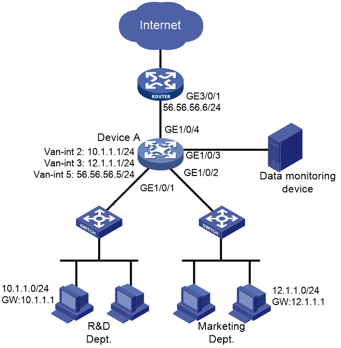
Network configuration
As shown in Figure 1, configure local port mirroring to monitor the Internet traffic and bidirectional traffic of the Marketing department and the Technical department.
Applicable hardware and software versions
The following matrix shows the hardware and software versions to which this configuration example is applicable:
|
Hardware |
Software version |
|
S6812 switch series S6813 switch series |
Release 6615Pxx, Release 6628Pxx |
|
S6550XE-HI switch series |
Release 6008 and later, Release 8106Pxx |
|
S6525XE-HI switch series |
Release 6008 and later, Release 8106Pxx |
|
S5850 switch series |
Release 8005 and later |
|
S5570S-EI switch series |
Release 11xx |
|
S5560X-EI switch series |
Release 63xx, Release 65xx, Release 6615Pxx, Release 6628Pxx |
|
S5560X-HI switch series |
Release 63xx, Release 65xx, Release 6615Pxx, Release 6628Pxx |
|
S5500V2-EI switch series |
Release 63xx, Release 65xx, Release 6615Pxx, Release 6628Pxx |
|
MS4520V2-30F switch |
Release 63xx, Release 65xx, Release 6615Pxx, Release 6628Pxx |
|
MS4520V2-30C switch MS4520V2-54C switch |
Release 65xx, Release 6615Pxx, Release 6628Pxx |
|
MS4520V2-28S switch MS4520V2-24TP switch |
Release 63xx |
|
S6520X-HI switch series S6520X-EI switch series |
Release 63xx, Release 65xx, Release 6615Pxx, Release 6628Pxx |
|
S6520X-SI switch series S6520-SI switch series |
Release 63xx, Release 65xx, Release 6615Pxx, Release 6628Pxx |
|
S5000-EI switch series |
Release 63xx, Release 65xx, Release 6615Pxx, Release 6628Pxx |
|
MS4600 switch series |
Release 63xx, Release 65xx, Release 6615Pxx, Release 6628Pxx |
|
ES5500 switch series |
Release 63xx, Release 65xx, Release 6615Pxx, Release 6628Pxx |
|
S5560S-EI switch series S5560S-SI switch series |
Release 63xx |
|
S5500V3-24P-SI switch S5500V3-48P-SI switch |
Release 63xx |
|
S5500V3-SI switch series (except S5500V3-24P-SI and S5500V3-48P-SI) |
Release 11xx |
|
S5170-EI switch series |
Release 11xx |
|
S5130S-HI switch series S5130S-EI switch series S5130S-SI switch series S5130S-LI switch series |
Release 63xx |
|
S5120V2-SI switch series S5120V2-LI switch series |
Release 63xx |
|
S5120V3-EI switch series |
Release 11xx |
|
S5120V3-36F-SI switch S5120V3-28P-HPWR-SI switch S5120V3-54P-PWR-SI switch |
Release 11xx |
|
S5120V3-SI switch series (except S5120V3-36F-SI, S5120V3-28P-HPWR-SI, and S5120V3-54P-PWR-SI) |
Release 63xx |
|
S5120V3-LI switch series |
Release 63xx |
|
S3600V3-EI switch series |
Release 11xx |
|
S3600V3-SI switch series |
Release 11xx |
|
S3100V3-EI switch series S3100V3-SI switch series |
Release 63xx |
|
S5110V2 switch series |
Release 63xx |
|
S5110V2-SI switch series |
Release 63xx |
|
S5000V3-EI switch series S5000V5-EI switch series |
Release 63xx |
|
S5000E-X switch series S5000X-EI switch series |
Release 63xx |
|
E128C switch E152C switch E500C switch series E500D switch series |
Release 63xx |
|
MS4320V2 switch series MS4320V3 switch series MS4300V2 switch series MS4320 switch series MS4200 switch series |
Release 63xx |
|
WS5850-WiNet switch series |
Release 63xx |
|
WS5820-WiNet switch series WS5810-WiNet switch series |
Release 63xx |
|
WAS6000 switch series |
Release 63xx |
|
IE4300-12P-AC switch IE4300-12P-PWR switch IE4300-M switch series IE4320 switch series |
Release 63xx |
Restrictions and guidelines
When you configure local port mirroring, follow these restrictions and guidelines:
· A local mirroring group takes effect only when you configure both source ports and the monitor port for the group. When you configure the monitor port, do not use a port of an existing mirroring group.
· Use a monitor port only for port mirroring, so the data monitoring device receives and analyzes only the mirrored traffic.
· For the correct operation of port mirroring, disable the spanning tree feature on the monitor port if it is a Layer 2 interface.
Procedures
# Create VLAN 2, VLAN 3, and VLAN 5.
<DeviceA> system-view
[DeviceA] vlan 2 3 5
# Create VLAN-interface 2 and VLAN-interface 3, and assign IP addresses to them separately, which will act as the gateways for VLAN 2 and VLAN 3 separately.
[DeviceA] interface vlan-interface 2
[DeviceA-Vlan-interface2] ip address 10.1.1.1 24
[DeviceA-Vlan-interface2] quit
[DeviceA] interface vlan-interface 3
[DeviceA-Vlan-interface3] ip address 12.1.1.1 24
[DeviceA-Vlan-interface3] quit
# Create VLAN-interface 5, and assign IP address 56.56.56.5 to the interface.
[DeviceA] interface vlan-interface 5
[DeviceA-Vlan-interface5] ip address 56.56.56.5 24
[DeviceA-Vlan-interface5] quit
# Assign GigabitEthernet 1/0/1 to VLAN 2, GigabitEthernet 1/0/2 to VLAN 3, and GigabitEthernet 1/0/4 to VLAN 5.
[DeviceA] interface gigabitethernet 1/0/1
[DeviceA-GigabitEthernet1/0/1] port access vlan 2
[DeviceA-GigabitEthernet1/0/1] quit
[DeviceA] interface gigabitethernet 1/0/2
[DeviceA-GigabitEthernet1/0/2] port access vlan 3
[DeviceA-GigabitEthernet1/0/2] quit
[DeviceA] interface gigabitethernet 1/0/4
[DeviceA-GigabitEthernet1/0/4] port access vlan 5
[DeviceA-GigabitEthernet1/0/4] quit
# Configure GigabitEthernet 1/0/3 as a trunk port, and assign it to VLAN 2 and VLAN 3.
[DeviceA] interface gigabitethernet 1/0/3
[DeviceA-GigabitEthernet1/0/3] port link-type trunk
[DeviceA-GigabitEthernet1/0/3] port trunk permit vlan 2 3
[DeviceA-GigabitEthernet1/0/3] quit
# Configure GigabitEthernet 1/0/1 and GigabitEthernet 1/0/2 as the source ports of the mirroring group.
[DeviceA] mirroring-group 1 mirroring-port gigabitethernet 1/0/1 gigabitethernet 1/0/2 inbound
# Configure GigabitEthernet 1/0/3 as the monitor port of the mirroring group.
[DeviceA] mirroring-group 1 monitor-port gigabitethernet 1/0/3
# Disable the spanning tree feature on GigabitEthernet 1/0/3.
[DeviceA] interface gigabitethernet 1/0/3
[DeviceA-GigabitEthernet1/0/3] undo stp enable
[DeviceA-GigabitEthernet1/0/3] quit
Verifying the configuration
1. Display information about mirroring group 1 on Device A.
[DeviceA] display mirroring-group 1
Mirroring group 1:
Type: Local
Status: Active
Mirroring port:
GigabitEthernet1/0/1 Inbound
GigabitEthernet1/0/2 Inbound
Monitor port: GigabitEthernet1/0/3
2. Use Wireshark for packet analysis:
# Ping 56.56.56.6 from a Technical department host (10.1.1.2). (Details not shown.)
# Use Wireshark on the data monitoring device to capture the ping packets.
Figure 2 Ping packet analysis in Wireshark
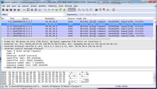
The analysis shows that the data monitoring device can monitor the packets sent from the Technical department.
Configuration files
|
|
IMPORTANT: The port link-mode command is not supported on the following switches: · S5130S-HI switch series. · S5130S-EI switch series. · S3100V3-EI switch series. · E128C switch. · E152C switch. · E500C switch series. · E500D switch series. · IE4300-12P-AC switch · IE4300-12P-PWR switch. · IE4300-M switch series. · IE4320 switch series. |
#
vlan 2
#
vlan 3
#
vlan 5
#
interface Vlan-interface2
ip address 10.1.1.1 255.255.255.0
#
interface Vlan-interface3
ip address 12.1.1.1 255.255.255.0
#
interface Vlan-interface5
ip address 56.56.56.5 255.255.255.0
#
mirroring-group 1 local
#
interface GigabitEthernet1/0/1
port link-mode bridge
port access vlan 2
mirroring-group 1 mirroring-port inbound
#
interface GigabitEthernet1/0/2
port link-mode bridge
port access vlan 3
mirroring-group 1 mirroring-port inbound
#
interface GigabitEthernet1/0/3
port link-mode bridge
port link-type trunk
port trunk permit vlan 1 to 3
undo stp enable
mirroring-group 1 monitor-port
#
interface GigabitEthernet1/0/4
port link-mode bridge
port access vlan 5
#
Example: Configure Layer 2 remote port mirroring
Network configuration
As shown in Figure 3, configure Layer 2 remote port mirroring to monitor the outgoing traffic from the Technical department.
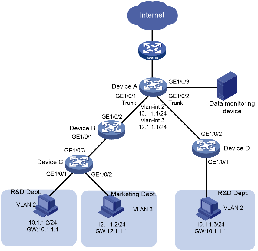
Analysis
To ensure correct forwarding of mirrored packets, assign the ports that connect intermediate devices to the source and destination devices to the remote probe VLAN.
Applicable hardware and software versions
The following matrix shows the hardware and software versions to which this configuration example is applicable:
|
Hardware |
Software version |
|
S6812 switch series S6813 switch series |
Release 6615Pxx, Release 6628Pxx |
|
S6550XE-HI switch series |
Release 6008 and later, Release 8106Pxx |
|
S6525XE-HI switch series |
Release 6008 and later, Release 8106Pxx |
|
S5850 switch series |
Release 8005 and later |
|
S5570S-EI switch series |
Release 11xx |
|
S5560X-EI switch series |
Release 63xx, Release 65xx, Release 6615Pxx, Release 6628Pxx |
|
S5560X-HI switch series |
Release 63xx, Release 65xx, Release 6615Pxx, Release 6628Pxx |
|
S5500V2-EI switch series |
Release 63xx, Release 65xx, Release 6615Pxx, Release 6628Pxx |
|
MS4520V2-30F switch |
Release 63xx, Release 65xx, Release 6615Pxx, Release 6628Pxx |
|
MS4520V2-30C switch MS4520V2-54C switch |
Release 65xx, Release 6615Pxx, Release 6628Pxx |
|
MS4520V2-28S switch MS4520V2-24TP switch |
Release 63xx |
|
S6520X-HI switch series S6520X-EI switch series |
Release 63xx, Release 65xx, Release 6615Pxx, Release 6628Pxx |
|
S6520X-SI switch series S6520-SI switch series |
Release 63xx, Release 65xx, Release 6615Pxx, Release 6628Pxx |
|
S5000-EI switch series |
Release 63xx, Release 65xx, Release 6615Pxx, Release 6628Pxx |
|
MS4600 switch series |
Release 63xx, Release 65xx, Release 6615Pxx, Release 6628Pxx |
|
ES5500 switch series |
Release 63xx, Release 65xx, Release 6615Pxx, Release 6628Pxx |
|
S5560S-EI switch series S5560S-SI switch series |
Release 63xx |
|
S5500V3-24P-SI switch S5500V3-48P-SI switch |
Release 63xx |
|
S5500V3-SI switch series (except S5500V3-24P-SI and S5500V3-48P-SI) |
Release 11xx |
|
S5170-EI switch series |
Release 11xx |
|
S5130S-HI switch series S5130S-EI switch series S5130S-SI switch series S5130S-LI switch series |
Release 63xx |
|
S5120V2-SI switch series S5120V2-LI switch series |
Release 63xx |
|
S5120V3-EI switch series |
Release 11xx |
|
S5120V3-36F-SI switch S5120V3-28P-HPWR-SI switch S5120V3-54P-PWR-SI switch |
Release 11xx |
|
S5120V3-SI switch series (except S5120V3-36F-SI, S5120V3-28P-HPWR-SI, and S5120V3-54P-PWR-SI) |
Release 63xx |
|
S5120V3-LI switch series |
Release 63xx |
|
S3600V3-EI switch series |
Release 11xx |
|
S3600V3-SI switch series |
Release 11xx |
|
S3100V3-EI switch series S3100V3-SI switch series |
Release 63xx |
|
S5110V2 switch series |
Release 63xx |
|
S5110V2-SI switch series |
Release 63xx |
|
S5000V3-EI switch series S5000V5-EI switch series |
Release 63xx |
|
S5000E-X switch series S5000X-EI switch series |
Release 63xx |
|
E128C switch E152C switch E500C switch series E500D switch series |
Release 63xx |
|
MS4320V2 switch series MS4320V3 switch series MS4300V2 switch series MS4320 switch series MS4200 switch series |
Release 63xx |
|
WS5850-WiNet switch series |
Release 63xx |
|
WS5820-WiNet switch series WS5810-WiNet switch series |
Release 63xx |
|
WAS6000 switch series |
Release 63xx |
|
IE4300-12P-AC switch IE4300-12P-PWR switch IE4300-M switch series IE4320 switch series |
Release 63xx |
Restrictions and guidelines
When you configure devices for remote port mirroring, configure them in the order of the destination device, the intermediate devices, and the source device.
When you configure the monitor port for the remote destination group on the destination device, follow these restrictions and guidelines:
· Do not use a port of an existing mirroring group.
· Use the monitor port only for port mirroring.
· For the correct operation of port mirroring, disable the spanning tree feature on the monitor port if it is a Layer 2 interface.
· For the monitor port to forward mirrored packets to the data monitoring device without VLAN tags, assign the monitor port to the remote probe VLAN as an access port.
When you configure the remote probe VLAN on the source and destination devices, follow these restrictions and guidelines:
· Use an existing static VLAN that is not in use.
· Use the remote probe VLAN for port mirroring exclusively.
· The remote mirroring groups on the source device and destination device must use the same remote probe VLAN. Use this VLAN only for the same remote mirroring group on the source device and destination device.
· Do not assign source ports of the remote source group to the remote probe VLAN.
· To ensure the operation of mirroring, do not enable any of the following features on the egress port:
¡ Spanning tree.
¡ 802.1X.
¡ IGMP snooping.
¡ Static ARP.
¡ MAC address learning.
· A port of an existing mirroring group cannot be configured as an egress port.
· A mirroring group contains only one egress port.
· To implement Layer 2 remote mirroring when the source ports are Layer 3 interfaces, you must use the egress port method.
Procedures
Configuring Device A (the destination device)
# Create VLANs 2 and 3.
<DeviceA> system-view
[DeviceA] vlan 2 to 3
# Create VLAN-interface 2 and assign an IP address to it.
[DeviceA] interface vlan-interface 2
[DeviceA-Vlan-interface2] ip address 10.1.1.1 24
[DeviceA-Vlan-interface2] quit
# Create VLAN-interface 3 and assign an IP address to it.
[DeviceA] interface vlan-interface 3
[DeviceA-Vlan-interface3] ip address 12.1.1.1 24
[DeviceA-Vlan-interface3] quit
# Configure GigabitEthernet 1/0/1 as a trunk port, and assign the port to VLANs 2, 3, and 5.
[DeviceA] interface gigabitethernet 1/0/1
[DeviceA-GigabitEthernet1/0/1] port link-type trunk
[DeviceA-GigabitEthernet1/0/1] port trunk permit vlan 2 3 5
[DeviceA-GigabitEthernet1/0/1] quit
# Configure GigabitEthernet 1/0/2 as a trunk port, and assign the port to VLANs 2 and 5.
[DeviceA] interface gigabitethernet 1/0/2
[DeviceA-GigabitEthernet1/0/2] port link-type trunk
[DeviceA-GigabitEthernet1/0/2] port trunk permit vlan 2 5
[DeviceA-GigabitEthernet1/0/2] quit
# Create a remote destination group.
[DeviceA] mirroring-group 1 remote-destination
# Create VLAN 5.
[DeviceA] vlan 5
[DeviceA-vlan5] quit
# Configure VLAN 5 as the remote probe VLAN of the remote destination group.
[DeviceA] mirroring-group 1 remote-probe vlan 5
# Configure GigabitEthernet 1/0/3 as the monitor port of the remote destination group.
[DeviceA] mirroring-group 1 monitor-port gigabitethernet 1/0/3
# Configure GigabitEthernet 1/0/3 as an access port, and assign the port to the remote probe VLAN.
[DeviceA] interface gigabitethernet 1/0/3
[DeviceA-GigabitEthernet1/0/3] port access vlan 5
# Disable the spanning tree feature on GigabitEthernet 1/0/3.
[DeviceA-GigabitEthernet1/0/3] undo stp enable
[DeviceA-GigabitEthernet1/0/3] quit
Configuring Device B (the intermediate device)
# Create VLANs 2 and 3.
<DeviceB> system-view
[DeviceB] vlan 2 to 3
# Create VLAN 5.
[DeviceB] vlan 5
[DeviceB-vlan5] quit
# Configure GigabitEthernet 1/0/1 as a trunk port, and assign the port to VLANs 2, 3, and 5.
[DeviceB] interface gigabitethernet 1/0/1
[DeviceB-GigabitEthernet1/0/1] port link-type trunk
[DeviceB-GigabitEthernet1/0/1] port trunk permit vlan 2 3 5
[DeviceB-GigabitEthernet1/0/1] quit
# Configure GigabitEthernet 1/0/2 as a trunk port, and assign the port to VLANs 2, 3, and 5.
[DeviceB] interface gigabitethernet 1/0/2
[DeviceB-GigabitEthernet1/0/2] port link-type trunk
[DeviceB-GigabitEthernet1/0/2] port trunk permit vlan 2 3 5
[DeviceB-GigabitEthernet1/0/2] quit
Configuring Device C (the source device)
# Create VLANs 2 and 3.
<DeviceC> system-view
[DeviceC] vlan 2 to 3
# Assign GigabitEthernet 1/0/1 to VLAN 2.
[DeviceC] interface gigabitethernet 1/0/1
[DeviceC-GigabitEthernet1/0/1] port access vlan 2
[DeviceC-GigabitEthernet1/0/1] quit
# Assign GigabitEthernet 1/0/2 to VLAN 3.
[DeviceC] interface gigabitethernet 1/0/2
[DeviceC-GigabitEthernet1/0/2] port access vlan 3
[DeviceC-GigabitEthernet1/0/2] quit
# Create a remote source group.
[DeviceC] mirroring-group 1 remote-source
# Create VLAN 5.
[DeviceC] vlan 5
[DeviceC-vlan5] quit
# Configure VLAN 5 as the remote probe VLAN for the remote source group.
[DeviceC] mirroring-group 1 remote-probe vlan 5
# Configure GigabitEthernet 1/0/1 as the source port of the remote source group and the mirroring direction as inbound.
[DeviceC] mirroring-group 1 mirroring-port gigabitethernet 1/0/1 inbound
# Configure GigabitEthernet 1/0/3 as the egress port of the remote source group.
[DeviceC] mirroring-group 1 monitor-egress gigabitethernet 1/0/3
# Configure GigabitEthernet 1/0/3 as a trunk port, and assign the port to VLANs 2, 3, and 5.
[DeviceC] interface gigabitethernet 1/0/3
[DeviceC-GigabitEthernet1/0/3] port link-type trunk
[DeviceC-GigabitEthernet1/0/3] port trunk permit vlan 2 3 5
[DeviceC-GigabitEthernet1/0/3] quit
# Disable the spanning tree feature and MAC address learning on the egress port GigabitEthernet 1/0/3.
[DeviceC-GigabitEthernet1/0/3] undo stp enable
[DeviceC-GigabitEthernet1/0/3] undo mac-address mac-learning enable
[DeviceC-GigabitEthernet1/0/3] quit
Configuring Device D (the source device)
# Create VLAN 2.
<DeviceD> system-view
[DeviceD] vlan 2
[DeviceD-vlan2] quit
# Assign GigabitEthernet 1/0/1 to VLAN 2.
[DeviceD] interface gigabitethernet 1/0/1
[DeviceD-GigabitEthernet1/0/1] port access vlan 2
[DeviceD-GigabitEthernet1/0/1] quit
# # Create remote source group 1.
[DeviceD] mirroring-group 1 remote-source
# Create VLAN 5.
[DeviceD] vlan 5
[DeviceD-vlan5] quit
# Configure VLAN 5 as the remote probe VLAN for the remote source group.
[DeviceD] mirroring-group 1 remote-probe vlan 5
# Configure GigabitEthernet 1/0/1 as the source port of the remote source group and the mirroring direction as inbound.
[DeviceD] mirroring-group 1 mirroring-port gigabitethernet 1/0/1 inbound
# Configure GigabitEthernet 1/0/2 as the egress port of the remote source group.
[DeviceD] mirroring-group 1 monitor-egress gigabitethernet 1/0/2
# Configure GigabitEthernet 1/0/2 as a trunk port, and assign the port to VLANs 2 and 5.
[DeviceD] interface gigabitethernet 1/0/2
[DeviceD-GigabitEthernet1/0/2] port link-type trunk
[DeviceD-GigabitEthernet1/0/2] port trunk permit vlan 2 5
# Disable the spanning tree feature and MAC address learning on the egress port GigabitEthernet 1/0/2.
[DeviceD-GigabitEthernet1/0/2] undo stp enable
[DeviceD-GigabitEthernet1/0/2] undo mac-address mac-learning enable
[DeviceD-GigabitEthernet1/0/2] quit
Verifying the configuration
1. Verify mirroring group configurations on devices:
# Display information about mirroring group 1 on Device C.
[DeviceC] display mirroring-group 1
Mirroring group 1:
Type: Remote source
Status: Active
Mirroring port:
GigabitEthernet1/0/1 Inbound
Monitor egress port: GigabitEthernet1/0/3
Remote probe VLAN: 5
# Display information about mirroring group 1 on Device A.
[DeviceA] display mirroring-group 1
Mirroring group 1:
Type: Remote destination
Status: Active
Monitor port: GigabitEthernet1/0/3
Remote probe VLAN: 5
2. Use Wireshark for packet analysis:
# Ping a Marketing department host (12.1.1.2) from a Technical department host (10.1.1.2). (Details not shown.)
# Use Wireshark on the data monitoring device to capture the ping packets.
Figure 4 Ping packet analysis in Wireshark
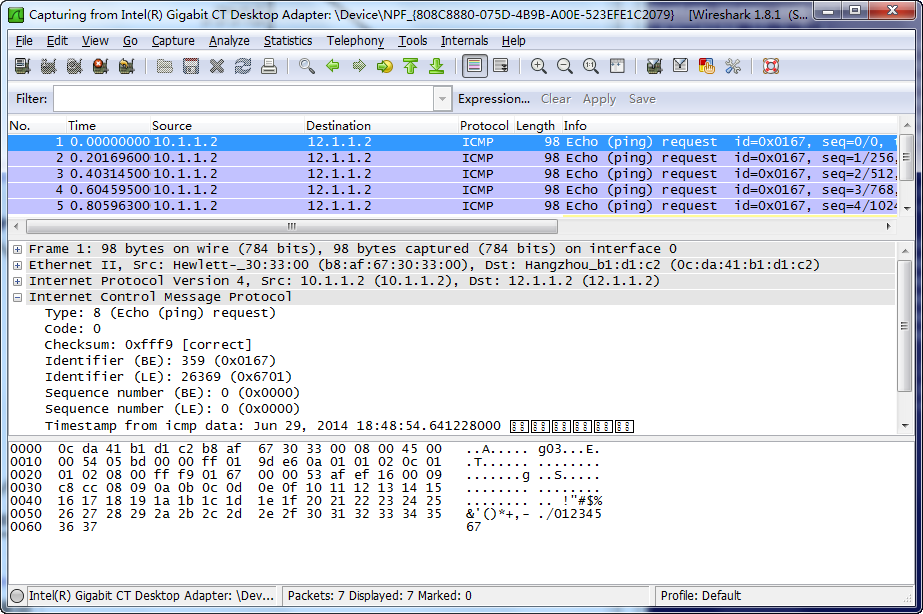
The analysis shows that the data monitoring device can monitor the outgoing traffic from the Technical department.
Configuration files
|
|
IMPORTANT: The port link-mode command is not supported on the following switches: · S5130S-HI switch series. · S5130S-EI switch series. · S3100V3-EI switch series. · E128C switch. · E152C switch. · E500C switch series. · E500D switch series. · IE4300-12P-AC switch · IE4300-12P-PWR switch. · IE4300-M switch series. · IE4320 switch series. |
· Device A:
#
mirroring-group 1 remote-destination
mirroring-group 1 remote-probe vlan 5
#
vlan 2 to 3
#
vlan 5
#
interface Vlan-interface2
ip address 10.1.1.1 255.255.255.0
#
interface Vlan-interface3
ip address 12.1.1.1 255.255.255.0
#
interface GigabitEthernet1/0/1
port link-mode bridge
port link-type trunk
port trunk permit vlan 1 to 3 5
#
interface GigabitEthernet1/0/2
port link-mode bridge
port link-type trunk
port trunk permit vlan 1 to 2 5
#
interface GigabitEthernet1/0/3
port link-mode bridge
port access vlan 5
undo stp enable
mirroring-group 1 monitor-port
#
· Device B:
#
vlan 2 to 3
#
vlan 5
#
interface GigabitEthernet1/0/1
port link-mode bridge
port link-type trunk
port trunk permit vlan 1 to 3 5
#
interface GigabitEthernet1/0/2
port link-mode bridge
port link-type trunk
port trunk permit vlan 1 to 3 5
#
· Device C:
#
mirroring-group 1 remote-source
mirroring-group 1 remote-probe vlan 5
#
vlan 2 to 3
#
vlan 5
#
interface GigabitEthernet1/0/1
port link-mode bridge
port access vlan 2
mirroring-group 1 mirroring-port inbound
#
interface GigabitEthernet1/0/2
port link-mode bridge
port access vlan 3
#
interface GigabitEthernet1/0/3
port link-mode bridge
port link-type trunk
port trunk permit vlan 1 to 3 5
mirroring-group 1 monitor-egress
· Device D:
#
mirroring-group 1 remote-source
mirroring-group 1 remote-probe vlan 5
#
vlan 2
#
vlan 5
#
interface GigabitEthernet1/0/1
port link-mode bridge
port access vlan 2
mirroring-group 1 mirroring-port inbound
#
interface GigabitEthernet1/0/2
port link-mode bridge
port link-type trunk
port trunk permit vlan 1 to 2 5
mirroring-group 1 monitor-egress
#
Example: Configuring Layer 3 remote port mirroring (ERSPAN)
Network configuration
As shown in Figure 5, configure Layer 3 remote port mirroring, so that the data monitoring device can monitor the traffic from the R&D department to Internet.
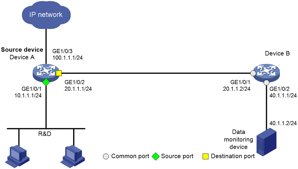
Analysis
When configuring Layer 3 remote port mirroring, first create a mirroring group, and then configure the source ports and monitor port for the mirroring group. Configure encapsulation parameters of mirrored packets when configuring the monitor port of the mirroring group.
Applicable hardware and software versions
The following matrix shows the hardware and software versions to which this configuration example is applicable:
|
Hardware |
Software version |
|
S6812 switch series S6813 switch series |
Release 6615Pxx, Release 6628Pxx |
|
S6550XE-HI switch series |
Not supported |
|
S6525XE-HI switch series |
Not supported |
|
S5850 switch series |
Not supported |
|
S5570S-EI switch series |
Not supported |
|
S5560X-EI switch series |
Release 65xx, Release 6615Pxx, Release 6628Pxx |
|
S5560X-HI switch series |
Release 65xx, Release 6615Pxx, Release 6628Pxx |
|
S5500V2-EI switch series |
Release 65xx, Release 6615Pxx, Release 6628Pxx |
|
MS4520V2-30F switch |
Release 65xx, Release 6615Pxx, Release 6628Pxx |
|
MS4520V2-30C switch MS4520V2-54C switch |
Release 65xx, Release 6615Pxx, Release 6628Pxx |
|
MS4520V2-28S switch MS4520V2-24TP switch |
Not supported |
|
S6520X-HI switch series S6520X-EI switch series |
Release 65xx, Release 6615Pxx, Release 6628Pxx |
|
S6520X-SI switch series S6520-SI switch series |
Release 65xx, Release 6615Pxx, Release 6628Pxx |
|
S5000-EI switch series |
Release 65xx, Release 6615Pxx, Release 6628Pxx |
|
MS4600 switch series |
Release 65xx, Release 6615Pxx, Release 6628Pxx |
|
ES5500 switch series |
Release 65xx, Release 6615Pxx, Release 6628Pxx |
|
S5560S-EI switch series S5560S-SI switch series |
Not supported |
|
S5500V3-24P-SI switch S5500V3-48P-SI switch |
Not supported |
|
S5500V3-SI switch series (except S5500V3-24P-SI and S5500V3-48P-SI) |
Not supported |
|
S5170-EI switch series |
Not supported |
|
S5130S-HI switch series S5130S-EI switch series S5130S-SI switch series S5130S-LI switch series |
Not supported |
|
S5120V2-SI switch series S5120V2-LI switch series |
Not supported |
|
S5120V3-EI switch series |
Not supported |
|
S5120V3-36F-SI switch S5120V3-28P-HPWR-SI switch S5120V3-54P-PWR-SI switch |
Not supported |
|
S5120V3-SI switch series (except S5120V3-36F-SI, S5120V3-28P-HPWR-SI, and S5120V3-54P-PWR-SI) |
Not supported |
|
S5120V3-LI switch series |
Not supported |
|
S3600V3-EI switch series |
Not supported |
|
S3600V3-SI switch series |
Not supported |
|
S3100V3-EI switch series S3100V3-SI switch series |
Not supported |
|
S5110V2 switch series |
Not supported |
|
S5110V2-SI switch series |
Not supported |
|
S5000V3-EI switch series S5000V5-EI switch series |
Not supported |
|
S5000E-X switch series S5000X-EI switch series |
Not supported |
|
E128C switch E152C switch E500C switch series E500D switch series |
Not supported |
|
MS4320V2 switch series MS4320V3 switch series MS4300V2 switch series MS4320 switch series MS4200 switch series |
Not supported |
|
WS5850-WiNet switch series |
Not supported |
|
WS5820-WiNet switch series WS5810-WiNet switch series |
Not supported |
|
WAS6000 switch series |
Not supported |
|
IE4300-12P-AC switch IE4300-12P-PWR switch IE4300-M switch series IE4320 switch series |
Not supported |
Procedures
Configuring Device A
# Assign IP address 20.1.1.1 to interface GigabitEthernet 1/0/2.
<DeviceA> system-view
[DeviceA] interface gigabitethernet 1/0/2
[DeviceA-GigabitEthernet1/0/2] port link-mode route
[DeviceA-GigabitEthernet1/0/2] ip address 20.1.1.1 24
[DeviceA-GigabitEthernet1/0/2] quit
# Assign IP addresses to other interfaces in the same way. (Details not shown.)
# Configure OSPF.
[DeviceA] ospf 1
[DeviceA-ospf-1] area 0
[DeviceA-ospf-1-area-0.0.0.0] network 10.1.1.0 0.0.0.255
[DeviceA-ospf-1-area-0.0.0.0] network 20.1.1.0 0.0.0.255
[DeviceA-ospf-1-area-0.0.0.0] quit
[DeviceA-ospf-1] quit
# Create local mirroring group 1.
[DeviceA] mirroring-group 1 local
# Configure a source port for local mirroring group 1.
[DeviceA] mirroring-group 1 mirroring-port gigabitethernet 1/0/1 inbound
# Configure the monitor port and encapsulation parameters of mirrored packets for local mirroring group 1.
[DeviceA] mirroring-group 1 monitor-port gigabitethernet 1/0/2 destination-ip 40.1.1.2 source-ip 20.1.1.1
Configuring Device B
# Configure OSPF.
<DeviceB> system-view
[DeviceB] ospf 1
[DeviceB-ospf-1] area 0
[DeviceB-ospf-1-area-0.0.0.0] network 20.1.1.0 0.0.0.255
[DeviceB-ospf-1-area-0.0.0.0] network 40.1.1.0 0.0.0.255
[DeviceB-ospf-1-area-0.0.0.0] quit
[DeviceB-ospf-1] quit
Verifying the configuration
# Display information about mirroring group 1 on Device A.
[DeviceA] display mirroring-group 1
Mirroring group 1:
Type: Local
Status: Active
Mirroring port:
GigabitEthernet1/0/1 Inbound
Monitor port: GigabitEthernet1/0/2
Encapsulation: Destination IP address 40.1.1.2
Source IP address 20.1.1.1
Destination MAC address 1025-4125-412b
Configuration files
|
|
IMPORTANT: The port link-mode command is not supported on the following switches: · S5130S-HI switch series. · S5130S-EI switch series. · S3100V3-EI switch series. · E128C switch. · E152C switch. · E500C switch series. · E500D switch series. · IE4300-12P-AC switch · IE4300-12P-PWR switch. · IE4300-M switch series. · IE4320 switch series. |
· Device A:
#
ospf 1
area 0.0.0.0
network 10.1.1.0 0.0.0.255
network 20.1.1.0 0.0.0.255
#
interface GigabitEthernet1/0/1
port link-mode route
ip address 10.1.1.1 255.255.255.0
mirroring-group 1 mirroring-port inbound
#
interface GigabitEthernet1/0/2
port link-mode route
ip address 20.1.1.1 255.255.255.0
mirroring-group 1 monitor-port destination-ip 40.1.1.2 source-ip 20.1.1.1
#
interface GigabitEthernet1/0/3
port link-mode route
ip address 100.1.1.1 255.255.255.0
#
mirroring-group 1 local
mirroring-group 1 mirroring-port gigabitethernet 1/0/1 inbound
mirroring-group 1 mirroring-port gigabitethernet 1/0/1 inbound
#
· Device B:
#
ospf 1
area 0.0.0.0
network 20.1.1.0 0.0.0.255
network 40.1.1.0 0.0.0.255
#
interface GigabitEthernet1/0/1
port link-mode route
ip address 20.1.1.2 255.255.255.0
#
interface GigabitEthernet1/0/2
port link-mode route
ip address 40.1.1.1 255.255.255.0
#
Example: Configuring local flow mirroring
Network configuration
As shown in Figure 6, configure local flow mirroring to mirror the following traffic:
· HTTP traffic from the Technical department.
· Packets that the Technical department hosts receive from the public server cluster during non-working hours from 18:00 to 08:30 (the next day) on working days.
Analysis
To configure local flow mirroring, you must perform the following tasks on Device A:
· Define traffic classes and configure match criteria to classify packets to be mirrored.
· Configure traffic behaviors to mirror the matching packets to the port that connects to the data monitoring device.
Applicable hardware and software versions
The following matrix shows the hardware and software versions to which this configuration example is applicable:
|
Hardware |
Software version |
|
S6812 switch series S6813 switch series |
Release 6615Pxx, Release 6628Pxx |
|
S6550XE-HI switch series |
Release 6008 and later, Release 8106Pxx |
|
S6525XE-HI switch series |
Release 6008 and later, Release 8106Pxx |
|
S5850 switch series |
Release 8005 and later |
|
S5570S-EI switch series |
Release 11xx |
|
S5560X-EI switch series |
Release 63xx, Release 65xx, Release 6615Pxx, Release 6628Pxx |
|
S5560X-HI switch series |
Release 63xx, Release 65xx, Release 6615Pxx, Release 6628Pxx |
|
S5500V2-EI switch series |
Release 63xx, Release 65xx, Release 6615Pxx, Release 6628Pxx |
|
MS4520V2-30F switch |
Release 63xx, Release 65xx, Release 6615Pxx, Release 6628Pxx |
|
MS4520V2-30C switch MS4520V2-54C switch |
Release 65xx, Release 6615Pxx, Release 6628Pxx |
|
MS4520V2-28S switch MS4520V2-24TP switch |
Release 63xx |
|
S6520X-HI switch series S6520X-EI switch series |
Release 63xx, Release 65xx, Release 6615Pxx, Release 6628Pxx |
|
S6520X-SI switch series S6520-SI switch series |
Release 63xx, Release 65xx, Release 6615Pxx, Release 6628Pxx |
|
S5000-EI switch series |
Release 63xx, Release 65xx, Release 6615Pxx, Release 6628Pxx |
|
MS4600 switch series |
Release 63xx, Release 65xx, Release 6615Pxx, Release 6628Pxx |
|
ES5500 switch series |
Release 63xx, Release 65xx, Release 6615Pxx, Release 6628Pxx |
|
S5560S-EI switch series S5560S-SI switch series |
Release 63xx |
|
S5500V3-24P-SI switch S5500V3-48P-SI switch |
Release 63xx |
|
S5500V3-SI switch series (except S5500V3-24P-SI and S5500V3-48P-SI) |
Release 11xx |
|
S5170-EI switch series |
Release 11xx |
|
S5130S-HI switch series S5130S-EI switch series S5130S-SI switch series S5130S-LI switch series |
Release 63xx |
|
S5120V2-SI switch series S5120V2-LI switch series |
Release 63xx |
|
S5120V3-EI switch series |
Release 11xx |
|
S5120V3-36F-SI switch S5120V3-28P-HPWR-SI switch S5120V3-54P-PWR-SI switch |
Release 11xx |
|
S5120V3-SI switch series (except S5120V3-36F-SI, S5120V3-28P-HPWR-SI, and S5120V3-54P-PWR-SI) |
Release 63xx |
|
S5120V3-LI switch series |
Release 63xx |
|
S3600V3-EI switch series |
Release 11xx |
|
S3600V3-SI switch series |
Release 11xx |
|
S3100V3-EI switch series S3100V3-SI switch series |
Release 63xx |
|
S5110V2 switch series |
Release 63xx |
|
S5110V2-SI switch series |
Release 63xx |
|
S5000V3-EI switch series S5000V5-EI switch series |
Release 63xx |
|
S5000E-X switch series S5000X-EI switch series |
Release 63xx |
|
E128C switch E152C switch E500C switch series E500D switch series |
Release 63xx |
|
MS4320V2 switch series MS4320V3 switch series MS4300V2 switch series MS4320 switch series MS4200 switch series |
Release 63xx |
|
WS5850-WiNet switch series |
Release 63xx |
|
WS5820-WiNet switch series WS5810-WiNet switch series |
Release 63xx |
|
WAS6000 switch series |
Release 63xx |
|
IE4300-12P-AC switch IE4300-12P-PWR switch IE4300-M switch series IE4320 switch series |
Release 63xx |
Procedures
1. Make sure Device A, Router, and the public server cluster can reach each other at Layer 3 and Device A and Internet can reach each other at Layer 3. (Details not shown.)
2. Assign interfaces to VLANs and assign IP addresses to VLAN interfaces:
# Create VLAN 2 and VLAN 5.
<DeviceA> system-view
[DeviceA] vlan 2 5
# Create VLAN-interface 2, and assign an IP address to it, which will act as the gateway of VLAN 2.
[DeviceA] interface vlan-interface 2
[DeviceA-Vlan-interface2] ip address 10.1.1.1 24
[DeviceA-Vlan-interface2] quit
# Create VLAN-interface 5, and assign IP address 56.56.56.5 to it.
[DeviceA] interface vlan-interface 5
[DeviceA-Vlan-interface5] ip address 56.56.56.5 24
[DeviceA-Vlan-interface5] quit
# Assign GigabitEthernet 1/0/1 to VLAN 2 and GigabitEthernet 1/0/3 to VLAN 5.
[DeviceA] interface gigabitethernet 1/0/1
[DeviceA-GigabitEthernet1/0/1] port access vlan 2
[DeviceA-GigabitEthernet1/0/1] quit
[DeviceA] interface gigabitethernet 1/0/3
[DeviceA-GigabitEthernet1/0/3] port access vlan 5
[DeviceA-GigabitEthernet1/0/3] quit
3. Configure a QoS policy to mirror HTTP traffic from the Technical department:
# Create ACL 3000 and configure a rule to match packets from the Technical department to the Internet.
[DeviceA] acl number 3000
[DeviceA-acl-ipv4-adv-3000] rule permit tcp destination-port eq 80 source 10.1.1.0 0.0.0.255
[DeviceA-acl-ipv4-adv-3000] quit
# Create traffic class classifier_internet, and configure the match criterion as ACL 3000.
[DeviceA] traffic classifier classifier_internet
[DeviceA-classifier-classifier_internet] if-match acl 3000
[DeviceA-classifier-classifier_internet] quit
# Create traffic behavior behavior_internet, and configure the action of mirroring traffic to GigabitEthernet 1/0/2.
[DeviceA] traffic behavior behavior_internet
[DeviceA-behavior-behavior_internet] mirror-to interface gigabitethernet 1/0/2
[DeviceA-behavior-behavior_internet] quit
# Create QoS policy policy_internet, and associate traffic class classifier_internet with traffic behavior behavior_internet in the QoS policy.
[DeviceA] qos policy policy_internet
[DeviceA-qospolicy-policy_internet] classifier classifier_internet behavior behavior_internet
[DeviceA-qospolicy-policy_internet] quit
4. Configure a QoS policy to mirror traffic that the Technical department hosts receive from the public server cluster:
# Create a periodic time range off-work1, setting it to be active between 0:00 and 8:30 during working days.
[DeviceA] time-range off-work1 0:00 to 8:30 working-day
# Create a periodic time range off-work2, setting it to be active between 18:00 and 24:00 during working days.
[DeviceA] time-range off-work2 18:00 to 24:00 working-day
# Create ACL 3001, and configure two rules to match packets from the public server cluster to the Technical department hosts in non-working hours on working days.
[DeviceA] acl number 3001
[DeviceA-acl-ipv4-adv-3001] rule permit ip destination 10.1.1.0 0.0.0.255 source 14.1.1.0 0.0.0.255 time-range off-work1
[DeviceA-acl-ipv4-adv-3001] rule permit ip destination 10.1.1.0 0.0.0.255 source 14.1.1.0 0.0.0.255 time-range off-work2
[DeviceA-acl-ipv4-adv-3001] quit
# Create traffic class classifier_server, and configure the match criterion as ACL 3001.
[DeviceA] traffic classifier classifier_server
[DeviceA-classifier-classifier_server] if-match acl 3001
[DeviceA-classifier-classifier_server] quit
# Create traffic behavior behavior_server, and configure the action of mirroring traffic to GigabitEthernet 1/0/2.
[DeviceA] traffic behavior behavior_server
[DeviceA-behavior-behavior_server] mirror-to interface gigabitethernet 1/0/2
[DeviceA-behavior-behavior_server] quit
# Create QoS policy policy_server, and associate traffic class classifier_server with traffic behavior behavior_server in the QoS policy.
[DeviceA] qos policy policy_server
[DeviceA-qospolicy-policy_server] classifier classifier_server behavior behavior_server
[DeviceA-qospolicy-policy_server] quit
5. Apply the QoS policies:
# Apply QoS policy policy_internet to the inbound direction of GigabitEthernet 1/0/1.
[DeviceA] interface gigabitethernet 1/0/1
[DeviceA-GigabitEthernet1/0/1] qos apply policy policy_internet inbound
[DeviceA-GigabitEthernet1/0/1] quit
# Apply QoS policy policy_server to the inbound direction of GigabitEthernet 1/0/3.
[DeviceA] interface gigabitethernet 1/0/3
[DeviceA-GigabitEthernet1/0/3] qos apply policy policy_server inbound
[DeviceA-GigabitEthernet1/0/3] quit
Verifying the configuration
1. Display local flow mirroring information on Device A.
[DeviceA] display qos policy interface
Interface: GigabitEthernet1/0/1
Direction: Inbound
Policy: policy_internet
Classifier: classifier_internet
Operator: AND
Rule(s) :
If-match acl 3000
Behavior: behavior_internet
Mirroring:
Mirror to the interface: GigabitEthernet1/0/2
Interface: GigabitEthernet1/0/3
Direction: Inbound
Policy: policy_server
Classifier: classifier_server
Operator: AND
Rule(s) :
If-match acl 3001
Behavior: behavior_server
Mirroring:
Mirror to the interface: GigabitEthernet1/0/2
2. Use Wireshark for packet analysis:
# Use a Technical department host (10.1.1.2) to access the IP address 46.46.46.4 and port 80 through Telnet. (Details not shown.)
# Use Wireshark on the data monitoring device to capture the packets.
Figure 7 HTTP traffic analysis in Wireshark
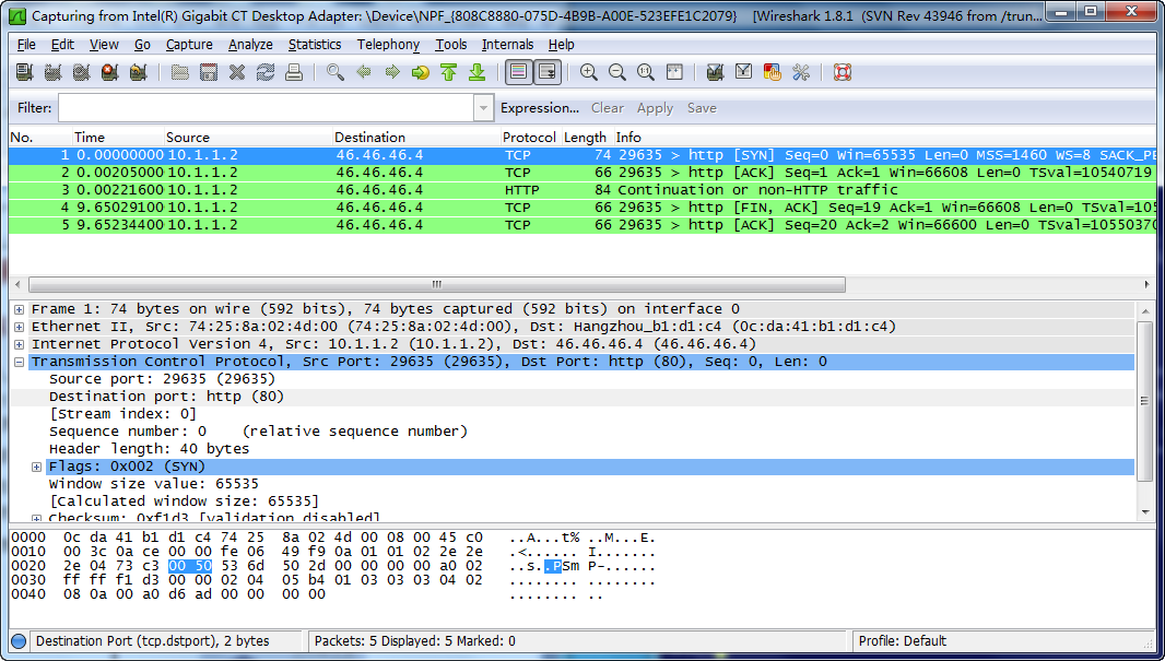
The analysis shows that the data monitoring device can monitor the HTTP traffic from the Technical department.
# On a non-working hour of a working day, ping a public server (14.1.1.2) from a Technical department host (10.1.1.2). (Details not shown.)
# Use Wireshark on the data monitoring device to capture the ping packets.
Figure 8 Ping packet analysis in Wireshark
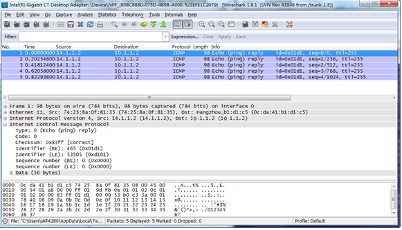
The analysis shows that the data monitoring device can monitor the traffic that the public server cluster send to the Technical department during non-working hours on working days.
Configuration files
|
|
IMPORTANT: The port link-mode command is not supported on the following switches: · S5130S-HI switch series. · S5130S-EI switch series. · S3100V3-EI switch series. · E128C switch. · E152C switch. · E500C switch series. · E500D switch series. · IE4300-12P-AC switch · IE4300-12P-PWR switch. · IE4300-M switch series. · IE4320 switch series. |
#
vlan 2
#
vlan 5
#
interface Vlan-interface2
ip address 10.1.1.1 255.255.255.0
#
interface Vlan-interface5
ip address 56.56.56.5 255.255.255.0
#
time-range off-work1 00:00 to 08:30 working-day
time-range off-work2 18:00 to 24:00 working-day
#
acl number 3000
rule 0 permit tcp source 10.1.1.0 0.0.0.255 destination-port eq www
acl number 3001
rule 0 permit ip source 14.1.1.0 0.0.0.255 destination 10.1.1.0 0.0.0.255 time-range off-work1
rule 5 permit ip source 14.1.1.0 0.0.0.255 destination 10.1.1.0 0.0.0.255 time-range off-work2
#
traffic classifier classifier_internet operator and
if-match acl 3000
traffic classifier classifier_server operator and
if-match acl 3001
#
traffic behavior behavior_internet
mirror-to interface GigabitEthernet1/0/2
traffic behavior behavior_server
mirror-to interface GigabitEthernet1/0/2
#
qos policy policy_internet
classifier classifier_internet behavior behavior_internet
qos policy policy_server
classifier classifier_server behavior behavior_server
#
interface GigabitEthernet1/0/1
port link-mode bridge
port access vlan 2
qos apply policy policy_internet inbound
#
interface GigabitEthernet1/0/3
port link-mode bridge
port access vlan 5
qos apply policy policy_server inbound
#
Example: Configuring Layer 3 remote flow mirroring (common Layer 3 routes)
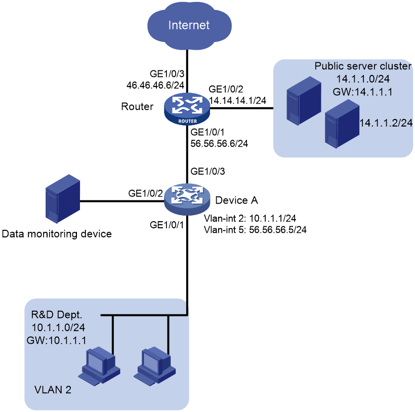
Network configuration
As shown in Figure 9, configure Layer 3 remote flow mirroring to enable the server to monitor the R&D Department's HTTP traffic to network 100.1.1.1.

Analysis
To configure remote flow mirroring, you must perform the following tasks:
· Define traffic classes and configure match criteria to classify packets to be mirrored.
· Configure traffic behaviors to mirror the matching packets to a port and re-encapsulate the matching packets so that the packets can be forwarded to the data monitoring server.
Applicable hardware and software versions
The following matrix shows the hardware and software versions to which this configuration example is applicable:
Procedures
Configuring Device A
1. Assign IP addresses to interfaces.
The following example assigns IP address 20.1.1.1 to GigabitEthernet 1/0/2.
<DeviceA> system-view
[DeviceA] interface gigabitethernet 1/0/2
[DeviceA-GigabitEthernet1/0/2] port link-mode route
[DeviceA-GigabitEthernet1/0/2] ip address 20.1.1.1 24
[DeviceA-GigabitEthernet1/0/2] quit
2. Configure the QoS policy policy_research:
# Create ACL 3000, and configure a rule to match packets from the R&D department to access the Internet.
[DeviceA] acl number 3000
[DeviceA-acl-adv-3000] rule permit tcp destination 100.1.1.0 0.0.0.255 destination-port eq 80 source 10.1.1.0 0.0.0.255
[DeviceA-acl-adv-3000] quit
# Create the traffic class classifier_research, and configure the match criterion as ACL 3000.
[DeviceA] traffic classifier classifier_research
[DeviceA-classifier-classifier_research] if-match acl 3000
[DeviceA-classifier-classifier_research] quit
# Create the traffic behavior behavior_research, configure the action of mirroring traffic to GigabitEthernet 1/0/2 and encapsulate the packets with source IP address 20.1.1.1 and destination IP address 40.1.1.2.
[DeviceA] traffic behavior behavior_research
[DeviceA-behavior-behavior_research] mirror-to interface gigabitethernet 1/0/2 destination-ip 40.1.1.2 source-ip 20.1.1.1
[DeviceA-behavior-behavior_research] quit
# Create the QoS policy policy_research.
[DeviceA] qos policy policy_research
# Associate the traffic class classifier_research with the traffic behavior behavior_research in the QoS policy.
[DeviceA-qospolicy-policy_research] classifier classifier_research behavior behavior_research
[DeviceA-qospolicy-policy_research] quit
# Apply the QoS policy to the inbound direction of GigabitEthernet 1/0/1.
[DeviceA] interface GigabitEthernet 1/0/1
[DeviceA-GigabitEthernet1/0/1] qos apply policy policy_research inbound
[DeviceA-GigabitEthernet1/0/1] quit
Configuring Device B
# Assign IP addresses to interfaces. The following example assigns IP address 20.1.1.2 to GigabitEthernet 1/0/1.
[DeviceB] interface gigabitethernet 1/0/1
[DeviceB-GigabitEthernet1/0/1] port link-mode route
[DeviceB-GigabitEthernet1/0/1] ip address 20.1.1.2
[DeviceB-GigabitEthernet1/0/1] quit
# Configure the OSPF protocol.
<DeviceB> system-view
[DeviceB] ospf 1
[DeviceB-ospf-1] area 0
[DeviceB-ospf-1-area-0.0.0.0] network 20.1.1.0 0.0.0.255
[DeviceB-ospf-1-area-0.0.0.0] network 40.1.1.0 0.0.0.255
[DeviceB-ospf-1-area-0.0.0.0] quit
[DeviceB-ospf-1] quit
Verifying the configuration
# Display remote flow mirroring configuration on Device A.
[DeviceA] display qos policy interface
Interface: GigabitEthernet1/0/1
Direction: Inbound
Policy: policy_research
Classifier: classifier_research
Operator: AND
Rule(s) :
If-match acl 3000
Behavior: behavior_research
Mirroring:
Mirror to the interface: GigabitEthernet1/0/2
Encapsulation: Destination IP address 40.1.1.2
Source IP address 20.1.1.1
Destination-MAC 1025-4125-412b
Configuration files
· Device A:
traffic classifier classifier_research operator and
traffic behavior behavior_research
mirror-to interface GigabitEthernet1/0/2 destination-ip 40.1.1.2 source-ip 20.1.1.1
classifier classifier_research behavior behavior_research
interface GigabitEthernet1/0/2
ip address 20.1.1.1 255.255.255.0
interface GigabitEthernet1/0/1
ip address 10.1.1.1 255.255.255.0
qos apply policy policy_research inbound
rule 0 permit tcp source 10.1.1.0 0.0.0.255 destination-port eq www
#
· Device B:
interface GigabitEthernet1/0/1
ip address 20.1.1.2 255.255.255.0
#
interface GigabitEthernet1/0/2
port link-mode route
ip address 40.1.1.1 255.255.255.0
#
Example: Configuring flow mirroring in a flexible way
Network configuration
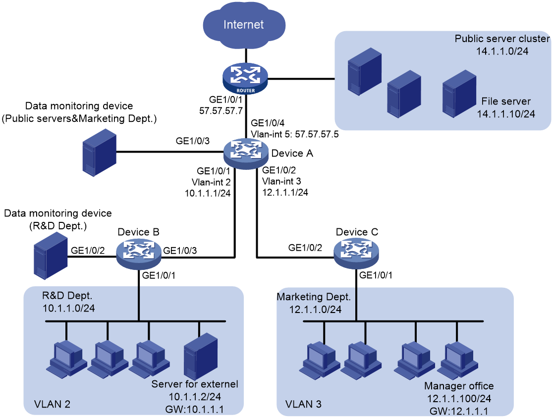
As shown in Figure 10, configure flow mirroring to monitor the network traffic by using the data monitoring devices as follows:
· On the data monitoring device connected to Device A:
¡ Monitor the traffic from public servers.
¡ Monitor the traffic from the file server only in the non-working hours (18:00 to 8:30 of the next day) on working days.
¡ Monitor the traffic from the Marketing department to the Internet, except the traffic from the Marketing department manager office to the Internet.
· On the data monitoring device connected to Device B:
¡ Monitor the traffic from the Technical department hosts and the server for external access.
¡ Monitor the outgoing traffic from the server in non-working hours (18:00 to 8:30 of the next day) on working days.
Analysis
To filter data from a specific source, use one of the following methods:
· Apply a QoS policy of denying traffic to the outgoing interface of the mirrored data. The data from the specified source is not received by the data monitoring device.
· Configure a class-behavior association to permit the data from the specified source, and then issue the class-behavior association before the class-behavior association for mirroring. Data from the specified source is not mirrored.
· Use the packet-filter command on the outgoing interface of the mirrored data. The data from the specified source is not received by the data monitoring device.
Applicable hardware and software versions
The following matrix shows the hardware and software versions to which this configuration example is applicable:
|
Hardware |
Software version |
|
S6812 switch series S6813 switch series |
Release 6615Pxx, Release 6628Pxx |
|
S6550XE-HI switch series |
Release 6008 and later, Release 8106Pxx |
|
S6525XE-HI switch series |
Release 6008 and later, Release 8106Pxx |
|
S5850 switch series |
Release 8005 and later |
|
S5570S-EI switch series |
Release 11xx |
|
S5560X-EI switch series |
Release 63xx, Release 65xx, Release 6615Pxx, Release 6628Pxx |
|
S5560X-HI switch series |
Release 63xx, Release 65xx, Release 6615Pxx, Release 6628Pxx |
|
S5500V2-EI switch series |
Release 63xx, Release 65xx, Release 6615Pxx, Release 6628Pxx |
|
MS4520V2-30F switch |
Release 63xx, Release 65xx, Release 6615Pxx, Release 6628Pxx |
|
MS4520V2-30C switch MS4520V2-54C switch |
Release 65xx, Release 6615Pxx, Release 6628Pxx |
|
MS4520V2-28S switch MS4520V2-24TP switch |
Release 63xx |
|
S6520X-HI switch series S6520X-EI switch series |
Release 63xx, Release 65xx, Release 6615Pxx, Release 6628Pxx |
|
S6520X-SI switch series S6520-SI switch series |
Release 63xx, Release 65xx, Release 6615Pxx, Release 6628Pxx |
|
S5000-EI switch series |
Release 63xx, Release 65xx, Release 6615Pxx, Release 6628Pxx |
|
MS4600 switch series |
Release 63xx, Release 65xx, Release 6615Pxx, Release 6628Pxx |
|
ES5500 switch series |
Release 63xx, Release 65xx, Release 6615Pxx, Release 6628Pxx |
|
S5560S-EI switch series S5560S-SI switch series |
Release 63xx |
|
S5500V3-24P-SI switch S5500V3-48P-SI switch |
Release 63xx |
|
S5500V3-SI switch series (except S5500V3-24P-SI and S5500V3-48P-SI) |
Release 11xx |
|
S5170-EI switch series |
Release 11xx |
|
S5130S-HI switch series S5130S-EI switch series S5130S-SI switch series S5130S-LI switch series |
Release 63xx |
|
S5120V2-SI switch series S5120V2-LI switch series |
Release 63xx |
|
S5120V3-EI switch series |
Release 11xx |
|
S5120V3-36F-SI switch S5120V3-28P-HPWR-SI switch S5120V3-54P-PWR-SI switch |
Release 11xx |
|
S5120V3-SI switch series (except S5120V3-36F-SI, S5120V3-28P-HPWR-SI, and S5120V3-54P-PWR-SI) |
Release 63xx |
|
S5120V3-LI switch series |
Release 63xx |
|
S3600V3-EI switch series |
Release 11xx |
|
S3600V3-SI switch series |
Release 11xx |
|
S3100V3-EI switch series S3100V3-SI switch series |
Release 63xx |
|
S5110V2 switch series |
Release 63xx |
|
S5110V2-SI switch series |
Release 63xx |
|
S5000V3-EI switch series S5000V5-EI switch series |
Release 63xx |
|
S5000E-X switch series S5000X-EI switch series |
Release 63xx |
|
E128C switch E152C switch E500C switch series E500D switch series |
Release 63xx |
|
MS4320V2 switch series MS4320V3 switch series MS4300V2 switch series MS4320 switch series MS4200 switch series |
Release 63xx |
|
WS5850-WiNet switch series |
Release 63xx |
|
WS5820-WiNet switch series WS5810-WiNet switch series |
Release 63xx |
|
WAS6000 switch series |
Release 63xx |
|
IE4300-12P-AC switch IE4300-12P-PWR switch IE4300-M switch series IE4320 switch series |
Release 63xx |
Procedures
Configuring Device A to mirror traffic from the public servers
1. Configure a QoS policy to mirror traffic from all public servers:
# Create ACL 2000 to match packets from subnet 14.1.1.0/24.
<DeviceA> system-view
[DeviceA] acl number 2000
[DeviceA-acl-ipv4-basic-2000] rule permit source 14.1.1.0 0.0.0.255
[DeviceA-acl-ipv4-basic-2000] quit
# Create traffic class classifier_servers, and configure the match criterion as ACL 2000.
[DeviceA] traffic classifier classifier_servers
[DeviceA-classifier-classifier_servers] if-match acl 2000
[DeviceA-classifier-classifier_servers] quit
# Create traffic behavior behavior_servers, and configure the action of mirroring traffic to GigabitEthernet 1/0/3.
[DeviceA] traffic behavior behavior_servers
[DeviceA-behavior-behavior_servers] mirror-to interface gigabitethernet 1/0/3
[DeviceA-behavior-behavior_servers] quit
# Create QoS policy policy_servers, and associate traffic class classifier_servers with traffic behavior behavior_servers in the QoS policy.
[DeviceA] qos policy policy_servers
[DeviceA-qospolicy-policy_servers] classifier classifier_servers behavior behavior_servers
[DeviceA-qospolicy-policy_servers] quit
# Apply QoS policy policy_servers to the inbound direction of GigabitEthernet 1/0/4.
[DeviceA] interface gigabitethernet 1/0/4
[DeviceA-GigabitEthernet1/0/4] qos apply policy policy_servers inbound
[DeviceA-GigabitEthernet1/0/4] quit
2. Configure a QoS policy to filter packets from the file server in working hours:
# Create a periodic time range work-time, setting it to be active between 8:30 and 18:00 during working days.
[DeviceA] time-range work-time 8:30 to 18:00 working-day
# Create ACL 2001, and configure a rule to match packets from 14.1.1.10 in working hours on working days.
[DeviceA] acl number 2001
[DeviceA-acl-ipv4-basic-2001] rule permit source 14.1.1.10 0.0.0.0 time-range work-time
[DeviceA-acl-ipv4-basic-2001] quit
# Create traffic class classifier_fileserver, and configure the match criterion as ACL 2001.
[DeviceA] traffic classifier classifier_fileserver
[DeviceA-classifier-classifier_fileserver] if-match acl 2001
[DeviceA-classifier-classifier_fileserver] quit
# Create traffic behavior behavior_fileserver, and configure the action of denying traffic.
[DeviceA] traffic behavior behavior_fileserver
[DeviceA-behavior-behavior_fileserver] filter deny
[DeviceA-behavior-behavior_fileserver] quit
# Create QoS policy policy_fileserver, and associate traffic class classifier_fileserver with traffic behavior behavior_fileserver in the QoS policy.
[DeviceA] qos policy policy_fileserver
[DeviceA-qospolicy-policy_fileserver] classifier classifier_fileserver behavior behavior_fileserver
[DeviceA-qospolicy-policy_fileserver] quit
# Apply QoS policy policy_fileserver to the outbound direction of GigabitEthernet 1/0/3.
[DeviceA] interface gigabitethernet 1/0/3
[DeviceA-GigabitEthernet1/0/3] qos apply policy policy_fileserver outbound
[DeviceA-GigabitEthernet1/0/3] quit
Configuring Device A to mirror the Internet traffic from the Marketing department
1. Create a traffic class and a traffic behavior for the packets:
# Create ACL 3000, and configure a rule to match packets from subnet 12.1.1.0/24.
[DeviceA] acl number 3000
[DeviceA-acl-ipv4-adv-3000] rule permit tcp destination-port eq 80 source 12.1.1.0 0.0.0.255
[DeviceA-acl-ipv4-adv-3000] quit
# Create traffic class classifier_market, and configure the match criterion as ACL 3000.
[DeviceA] traffic classifier classifier_market
[DeviceA-classifier-classifier_market] if-match acl 3000
[DeviceA-classifier-classifier_market] quit
# Create traffic behavior behavior_market, and configure the action of mirroring traffic to GigabitEthernet 1/0/3.
[DeviceA] traffic behavior behavior_market
[DeviceA-behavior-behavior_market] mirror-to interface gigabitethernet 1/0/3
[DeviceA-behavior-behavior_market] quit
2. Create a traffic class and a traffic behavior for the packets from the manager office:
# Create ACL 3001, and configure a rule to match packets from 12.1.1.100.
[DeviceA] acl number 3001
[DeviceA-acl-ipv4-adv-3001] rule permit tcp destination-port eq 80 source 12.1.1.100 0.0.0.0
[DeviceA-acl-ipv4-adv-3001] quit
# Create traffic class classifier_market_mgr, and configure the match criterion as ACL 3001.
[DeviceA] traffic classifier classifier_market_mgr
[DeviceA-classifier-classifier_market_mgr] if-match acl 3001
[DeviceA-classifier-classifier_market_mgr] quit
# Create traffic behavior behavior_market_mgr, and configure the action of permitting traffic to pass through.
[DeviceA] traffic behavior behavior_market_mgr
[DeviceA-behavior-behavior_market_mgr] filter permit
[DeviceA-behavior-behavior_market_mgr] quit
3. Create a QoS policy and associate the traffic classes and traffic behaviors:
# Create QoS policy policy_market.
[DeviceA] qos policy policy_market
# Associate traffic class classifier_market_mgr with traffic behavior behavior_market_mgr in the QoS policy.
[DeviceA-qospolicy-policy_market] classifier classifier_market_mgr behavior behavior_market_mgr
# Associate traffic class classifier_market with traffic behavior behavior_market in the QoS policy.
[DeviceA-qospolicy-policy_market] classifier classifier_market behavior behavior_market
# Display the sequence of issuing the class–behavior associations.
[DeviceA-qospolicy-policy_market] display this
#
qos policy policy_market
classifier classifier_market_mgr behavior behavior_market_mgr
classifier classifier_market behavior behavior_market
#
return
[DeviceA-qospolicy-policy_market] quit
The output shows that the class–behavior association for the manager office are issued first. The packets from the manager office to access the Internet are not mirrored.
4. Apply QoS policy policy_market to the inbound direction of GigabitEthernet 1/0/2.
[DeviceA] interface gigabitethernet 1/0/2
[DeviceA-GigabitEthernet1/0/2] qos apply policy policy_market inbound
[DeviceA-GigabitEthernet1/0/2] quit
Configuring Device B to mirror traffic from the Technical department
1. Configure local mirroring on Device B:
# Create local mirroring group 1.
<DeviceB> system-view
[DeviceB] mirroring-group 1 local
# Configure the mirroring group to monitor the incoming traffic of the port GigabitEthernet 1/0/1.
[DeviceB] mirroring-group 1 mirroring-port gigabitethernet 1/0/1 inbound
# Configure GigabitEthernet 1/0/2 as the monitor port of the mirroring group.
[DeviceB] mirroring-group 1 monitor-port gigabitethernet 1/0/2
2. Configure an ACL to filter the outgoing traffic from the server (10.1.1.2) in working hours:
# Create a periodic time range work-time, setting it to be active between 8:30 and 18:00 during working days.
[DeviceB] time-range work-time 8:30 to 18:00 working-day
# Create ACL 2000, and configure a rule to deny packets from 10.1.1.2 in working hours on working days.
[DeviceB] acl number 2000
[DeviceB-acl-ipv4-basic-2000] rule deny source 10.1.1.2 0.0.0.0 time-range work-time
[DeviceB-acl-ipv4-basic-2000] quit
# Apply ACL 2000 to filter the outgoing traffic on GigabitEthernet 1/0/2.
[DeviceB] interface gigabitethernet1/0/2
[DeviceB-GigabitEthernet1/0/2] packet-filter 2000 outbound
[DeviceB-GigabitEthernet1/0/2] quit
Verifying the configuration
1. Verify flow mirroring configurations on devices:
# Display flow mirroring information on Device A.
[DeviceA] display qos policy interface
Interface: GigabitEthernet1/0/2
Direction: Inbound
Policy: policy_market
Classifier: classifier_market_mgr
Operator: AND
Rule(s) : If-match acl 3001
Behavior: behavior_market_mgr
Filter enable: Permit
Classifier: classifier_market
Operator: AND
Rule(s) : If-match acl 3000
Behavior: behavior_market
Mirroring:
Mirror to the interface: GigabitEthernet1/0/3
Interface: GigabitEthernet1/0/3
Direction: Outbound
Policy: policy_fileserver
Classifier: classifier_fileserver
Operator: AND
Rule(s) : If-match acl 2001
Behavior: behavior_fileserver
Mirroring:
Mirror to the interface: GigabitEthernet1/0/3
Interface: GigabitEthernet1/0/4
Direction: Inbound
Policy: policy_servers
Classifier: classifier_servers
Operator: AND
Rule(s) : If-match acl 2000
Behavior: behavior_servers
Mirroring:
Mirror to the interface: GigabitEthernet1/0/3
# Display information about mirroring group 1 on Device B.
[DeviceB] display mirroring-group 1
Mirroring group 1:
Type: Local
Status: Active
Mirroring port:
GigabitEthernet1/0/1 Inbound
Monitor port: GigabitEthernet1/0/2
2. Use Wireshark for packet analysis:
# Use a Marketing department host (12.1.1.2) and the manager's host (12.1.1.100) to access the IP address 57.57.57.7 and port 80 through Telnet. (Details not shown.)
# Use Wireshark on the data monitoring device connected to Device A to capture the packets.
Figure 11 HTTP traffic analysis in Wireshark
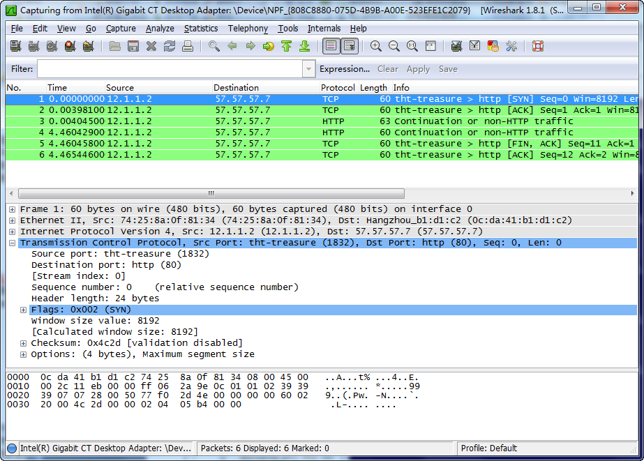
The analysis shows that the data monitoring device monitors the traffic only from the Marketing department host (12.1.1.2). The traffic from the manager office is not monitored.
Configuration files
|
|
IMPORTANT: The port link-mode command is not supported on the following switches: · S5130S-HI switch series. · S5130S-EI switch series. · S3100V3-EI switch series. · E128C switch. · E152C switch. · E500C switch series. · E500D switch series. · IE4300-12P-AC switch · IE4300-12P-PWR switch. · IE4300-M switch series. · IE4320 switch series. |
· Device A:
#
time-range work-time 08:30 to 18:00 working-day
#
acl number 2000
rule 0 permit source 14.1.1.0 0.0.0.255
acl number 2001
rule 0 permit source 14.1.1.10 0 time-range work-time
#
acl number 3000
rule 0 permit tcp source 12.1.1.0 0.0.0.255 destination-port eq www
acl number 3001
rule 0 permit tcp source 12.1.1.100 0 destination-port eq www
#
traffic classifier classifier_servers operator and
if-match acl 2000
traffic classifier classifier_fileserver operator and
if-match acl 2001
traffic classifier classifier_market operator and
if-match acl 3000
traffic classifier classifier_market_mgr operator and
if-match acl 3001
#
traffic behavior behavior_servers
mirror-to interface GigabitEthernet1/0/3
traffic behavior behavior_fileserver
filter deny
traffic behavior behavior_market
mirror-to interface GigabitEthernet1/0/3
traffic behavior behavior_market_mgr
filter permit
#
qos policy policy_fileserver
classifier classifier_fileserver behavior behavior_fileserver
qos policy policy_market
classifier classifier_market_mgr behavior behavior_market_mgr
classifier classifier_market behavior behavior_market
qos policy policy_servers
classifier classifier_servers behavior behavior_servers
#
interface GigabitEthernet1/0/1
port link-mode bridge
port link-type trunk
port trunk permit vlan 1 to 2
#
interface GigabitEthernet1/0/2
port link-mode bridge
port link-type trunk
port trunk permit vlan 1 3
qos apply policy policy_market inbound
#
interface GigabitEthernet1/0/3
port link-mode bridge
qos apply policy policy_fileserver outbound
#
interface GigabitEthernet1/0/4
port link-mode bridge
port access vlan 5
ip address 57.57.57.5 255.255.255.0
qos apply policy policy_servers inbound
#
· Device B:
#
mirroring-group 1 local
#
time-range work-time 08:30 to 18:00 working-day
#
acl number 2000
rule 0 deny source 10.1.1.2 0 time-range work-time
#
interface GigabitEthernet1/0/1
port link-mode bridge
port access vlan 2
mirroring-group 1 mirroring-port inbound
#
interface GigabitEthernet1/0/2
port link-mode bridge
packet-filter 2000 outbound
mirroring-group 1 monitor-port
#
